This chamber is the downside of the invention - it has to be there, but its undesirable. If you could find a way to elliminate it then youd REALLY have an invention on your hands.
Hi all
I've sometimes fantasized about using a vacuum in sealed enclosures, behind drivers, diaphragms etc. It would be ideal for this V2 volume as well EXCEPT that in all cases, the static forces on the moving piston(s) is way too high. What's needed is a suspension that offers reasonable compliance while withstanding a high static force.
Second choice (after vacuum) for filling a sealed cabinet would be Hydrogen or Helium. This won't help with compliance or other lumped parameters, but all acoustic resonances will be pushed up one and a half to two octaves (depending on your choice of gas).
That makes it easier to get all resonance modes up out of the passband e.g. in dedicated bass or midrange boxes, horn back-chambers etc.
Effective sealing won't be trivial, but should be do-able.
Cheers - Godfrey
p.s. I just realized an acoustic lever could be used to provide the suspension required by vacuum.
Reliability of the lever itself could be an issue because it gets a pretty good workout.
Hi EarlWhen I get far enough ahead to have the lever made. Without that part you have nothing and that part does not exist.
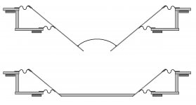
Wouldn't a "leverless" variation be simpler in practical terms? One possibility is shown below.
The green part could be a lightweight aluminum cone. The deep, straight-sided cone should put the breakup modes well above the frequency range of interest. There's a bit of wasted space inside the cone but it's not as bad as it looks (there's not much volume inside a cone).
The blue part could be round PVC pipe. The shape will help minimize V1 and maximize V2.
I'm not sure what would be best for the suspension (shown in red) - rubber roll / corrugated paper / something else that won't sag or flap too much?
______________________________________________
Another "leverless" approach would be to use two woofer cones (of different diameters) mounted back-to-back and attached to each other where the spiders and voice coils would normally attach.
That should be easy to prototype with a couple of passive radiators, an angle-grinder and some epoxy glue.
Added bonus: it's a legitimate excuse to vent some frustration by attacking drivers with angle-grinders. 😀
Regards - Godfrey
Attachments
Last edited:
I first ran across Earl's AL concept several years ago while I was looking into PR-based bandpass alignments. I like the idea of using acoustic filters over electrical ones, and also avoiding use of long ports in bandpass alignments whose resonances can get in the way.
At the time, I did some rough drawings of how to construct the AL resonator element largely with off-the-shelf parts and no need for unique castings, etc. Godfrey's drawing reminded me of it, and I've attached it below.
The frame is made up of two aluminum hoops--one for the outer mounting flange and and a smaller-diameter one for the inner. These are fastened together with cylindrical posts with bolts running through them.
The diaphragm and surrounds are off-the-shelf woofer soft-parts.
If you want more mass and a shallower profile, glue in a thin piece of MDF and cut away the excess cone below it.
There you go, Earl. No tooling to speak of, just some aluminum hoops, a bit of drilling, and some gluing.
Design free of charge, and worth every penny.
Attachments
I've sometimes fantasized about using a vacuum in sealed enclosures, Effective sealing won't be trivial, but should be do-able.
You will get slow diffusion of the gas through almost any material that is not glass or metal. The food industry deals with this problem: High-Barrier Packaging: Yesterday, Today, and Tomorrow
Sheldon
Operationally,
is no different than
It just looks different.
And
is no different than
It just looks different.
And
appears in the patent.Another "leverless" approach would be to use two woofer cones (of different diameters) mounted back-to-back and attached to each other where the spiders and voice coils would normally attach
Last edited:
Exactly - I just though it might be easier from a practical construction point of view.Operationally, (Godfrey's pic) is no different than (Earl's pic) It just looks different.
Oopsie! - I'll admit to not bothering to read the patent. 😱... appears in the patent.
I thought the picture in the first post, together with the term "acoustic lever" pretty much said everything that needed to be said.
I've developed a reluctance to reading patents, since most of them appear to have been written by lawyers rather than engineers, and are (to me, anyway) difficult to decipher.
Cheers - Godfrey
Last edited:
Sorry, I missed this earlier. (and the various levers described in the patent, which I've now read)In practice there would only be a single unit, not two connected by a rod as discussed (this would be very inefficient).
😱😱😱
No, IMHO that's just two drivers nailed to a plank of wood with a fancy name to justify the price.
What's interesting is their trademark claim for the name "Acoustic Lever". e.g. quote from the link above: "Using Stealth’s Acoustic Lever™ technology, ..."
How do they get to own the name when Earl owns the patent, and the patent explicitly uses that name?
To add insult to injury, the only thing being leveraged there is marketing hype.
Cheers - Godfrey
Last edited:
Sorry, I missed this earlier. (and the various levers described in the patent, which I've now read)
😱😱😱
No, IMHO that's just two drivers nailed to a plank of wood with a fancy name to justify the price.
What's interesting is their trademark claim for the name "Acoustic Lever". e.g. quote from the link above: "Using Stealth’s Acoustic Lever™ technology, ..."
How do they get to own the name when Earl owns the patent, and the patent explicitly uses that name?
To add insult to injury, the only thing being leveraged there is marketing hype.
Cheers - Godfrey
A patent is not a trademark or a copyright. They can use "Acoustic Lever" but they could never copyright or trademark it because it is so clearly used in my patent.
I've developed a reluctance to reading patents, since most of them appear to have been written by lawyers rather than engineers, and are (to me, anyway) difficult to decipher.
Cheers - Godfrey
You mean you have a problem with a nail being called an elongated metallic interfribrous fastener?
... and whereas said nail (G in fig 3) shall be required to pass through hole C in order to affix block E to plank A (described in subsection 14.3 above), it should be noted that, notwithstanding the aforementioned ...You mean you have a problem with a nail being called an elongated metallic interfribrous fastener?
Me => 😱 =>
 =>
=>  =>
=> 
Last edited:
Now, I'm not 100% sure on this, but I think the Logitech "sub" to my right employs an acoustic lever. There's a 3.5" high excursion woofer, with a port in parallel, driving an 8" passive radiator thingy... I thought it was a quasi 6th order bandpass with PR, but after reading this (and blocking the mentioned port), it seems more like an acoustic lever.
Here's an image on the inside, looking through where the PR is mounted.
http://www.outta.org/articles/logitech_z4_review/first_chamber.jpg
If it turns out that Logitech have used the technology in your patent, you might be able to get some money out.
Chris
PS - sorry if this was a waste of time.
Here's an image on the inside, looking through where the PR is mounted.
http://www.outta.org/articles/logitech_z4_review/first_chamber.jpg
If it turns out that Logitech have used the technology in your patent, you might be able to get some money out.
Chris
PS - sorry if this was a waste of time.
Edit - I don't think the mentioned sub does use an acoustic lever - I've looked at the AL again, and it seems to be 2 diaphgrams - one for the driver, one for the outside world. The two are linked mechanically. The internal (driver) diaphram is smaller than the driver Sd, so moves further. This pushes the outside diaphram further than if it was to be directly driven by the speaker.
Sorry for the confusion
Chris
Sorry for the confusion
Chris
I believe that is simply a passive radiator on a bandpass, yes bascially a nonsymetric 6th order system. Unless you have some more photos or drawings etc. that show differently.
Can't we adopt 10-15" speaker chassis? Just reduce rear suspension aperture. Membrane custom made of expanded polystyrene?
Can't we adopt 10-15" speaker chassis? Just reduce rear suspension aperture. Membrane custom made of expanded polystyrene?
Of course. Making them is not hard, its paying for them that poses a problem.
Edit - I don't think the mentioned sub does use an acoustic lever - I've looked at the AL again, and it seems to be 2 diaphgrams - one for the driver, one for the outside world. The two are linked mechanically. The internal (driver) diaphram is smaller than the driver Sd, so moves further. This pushes the outside diaphram further than if it was to be directly driven by the speaker.
Sorry for the confusion
Chris
If thats how it works then it is an acoustic level. Does anyone have a drawing, sketch or model number?
It looks to be a series tuned bandpass with a passive radiator instead of a port on the outer chamber.
-David
-David
It looks to be a series tuned bandpass with a passive radiator instead of a port on the outer chamber.
-David
A lever is a form of passive radiator, but one with different areas on the two sides.
.......
Of course we could always just evacuate this space and then it goes away acoustically, but that adds another problem. Oh well.
The lever would then be pushed towards the smaller side, because
outside pressure on both areas is the same resulting in a proportionally
higher force pushing the larger area inside the box.
Inserting a compensation spring ? Would introduce
nonlinear behaviour IMO, but could maybe adjusted to be small
for the excursions needed. Anyhow vacuum constrution seems
a little crazy.
- Status
- Not open for further replies.
- Home
- Loudspeakers
- Multi-Way
- Geddes on Acoustic Lever