2N2222A phono preamp grounding scheme
Hello Ivey,
Thank you! This is very nice.
Please suggest a grounding scheme for your 2N2222A circuit and power supply. I ask because most turntables I've seen have a separate ground wire that was attached to the back of the preamp on a dedicated grounding screw/lug and I was never sure how this all fit in to the big picture.
Best regards,
Obe1
Hi,
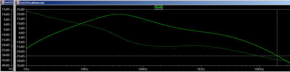
Change C3 (in your sim) from 1uF to 1.5nF.
Edit: You'll find my source here: http://www.diyaudio.com/forums/analog-line-level/158918-2n2222a-phono-preamp-3.html#post2050332
Change C3 (in your sim) from 1uF to 1.5nF.
Edit: You'll find my source here: http://www.diyaudio.com/forums/analog-line-level/158918-2n2222a-phono-preamp-3.html#post2050332
Last edited:
Hi,
Change C3 (in your sim) from 1uF to 1.5nF.
much better, thank you 🙂
desired:

and simulated in attachment
20Hz is -2.75dB off, 1KHz is 1.31dB off, 20KHz is -4.4dB off. (source is 9mV)
pretty respectable, but clearly some room for improvement. i'll breadboard it first 🙂
Attachments
I am Sorry Gentlemen:
I was away on another forum, but I am back now.
I am building the phono preamp for two others, and I came across a site that sales JAN2N2222A transistors at $00.45 cent ea. It is called
Surplus-Electronics-Sales.Com
Yes, the design of the Phono PreAmp can be improved in all areas. That is why I posted it. Now, it belongs to all of you guys. To use it as is, or to mod it as you see fit.
I have done many changes to this design in the past. By changing the input transistor with a more sensitive one, like the BC107. I have replaced all the transistors with 2N4401's and even used very hi end parts. And the results were good to outstanding.
The idea of this thread is to build a simple, yet effective phono preamp, with easy available parts, and do it at low low cost. PLus, later on, add the tonal circuit and line circuit with the same scheme in mind. Then, place it all in this jazzy case design I am cooking up. And have this beautiful piece of hifi gear to use, keep, or trade.
We must remember that there are better transistors out there other than the 2N2222A. But the 2N2222A is a very useful transistor.
Like most of us, the 2N2222A is old, but reliable.
We have all looked at the data sheet of a 2N2222A, but have you ever really, really studied it and compared it to other transistors. You will find out that you can get by without so many transistors that you may have today. And save a small sum of money.
Keep in mind, that at low small signal levels, the 2N2222A does a great job. And with a maximum noise level of 4db, it is more silent than even the BC107. But it's high speed switching and high ft, is also useful.
I found it to be a better chopper and switcher than those transistors designed for those purposes.
To me, the 2N2222A is like chicken. Everything taste like chicken. And finger lick-in good.
But truly it is all up to you. What ever it is that you want to do.
Happy Trails guys.
And I will post the second half of the preamp, the tone control-line amp circuit before I attend by son's third wedding.
He is still searching for a girl like his mother. No clue that kid. No clue.
Take Care
Ivey
Last edited:
i don t understand why people still stick with these kinds
of circuits, moreover , using inadequate transistors...
with about an EIN of 13 nV/sqrt hz noise, although decent for
the 60 s , it s well over any very cheap opamp..
a NE5532, which is a 30 years old circuit, has 4.5 nV/sqrt hz,
about 12 db less noise...
of circuits, moreover , using inadequate transistors...
with about an EIN of 13 nV/sqrt hz noise, although decent for
the 60 s , it s well over any very cheap opamp..
a NE5532, which is a 30 years old circuit, has 4.5 nV/sqrt hz,
about 12 db less noise...
Wahab:
Because they are easy to play with.
You can mod them such easier than opamps.
Opamp's are made up of 12 to 15 transistors, resistors, and caps. You can not change the insides character of an Opamp, you must settle with what ever the Opamp brings to the table.
You can only change the supporting components, with the transistor, you can change everything, and start over if you like. With the Opamp, you can not.
With the transistor circuit, you have total control of the product and the way it will sound.
Take Care
Ivey
Hello Ivey,
Looking forward to you promised line stage design and chassis / enclosure concepts.
Best regards,
Obe1
Looking forward to you promised line stage design and chassis / enclosure concepts.
Best regards,
Obe1
Because they are easy to play with.
You can mod them such easier than opamps.
Opamp's are made up of 12 to 15 transistors, resistors, and caps. You can not change the insides character of an Opamp, you must settle with what ever the Opamp brings to the table.
You can only change the supporting components, with the transistor, you can change everything, and start over if you like. With the Opamp, you can not.
With the transistor circuit, you have total control of the product and the way it will sound.
Take Care
Ivey
100% agree...and this one need some tweaks...
with the values used, biases are inadequates, as the negative going
of the signal can t pass about 2.5V peak , due to the second stage having
a high emitter voltage...
it result that clipping is extremely unsymetrical...
Wahab:
Right on>
Ok, fix it. Get it to perform the way you feel it would be a better mouse trap. And share it with us. Show us how you would do it. And we can learn something from you. And add it to the things that we already know.
There are many ways to cook chicken. So I am asking you to share your favorite recipes with the rest of us.
This is a forum for fun and learning. We all can use some education.
I showed you my way, now I ask you to show me yours.
I wait your reply, my friend.
Take Care
Ivey
hi, ivey,
some apologies, as i simulated with a fairly low impedance at
at the output..with a normal load, output max is 13V pp, relatively
symetrical inb clipping..
using a 20K load, simulations show that
distorsion is about 0.02% at 500mV rms output, at 1Khz...
and noise is fairly low , at 2.5 nV/sqrt hz, of course with a very
low impedance generator, but s + n/n ratios of 75 db could be achievable,
although lower noise devices such as bc109C would do it better by about
3 db at least....
anyway, it works, comfortably well...
regards,
wahab
Wahab:
So, as you have discovered, it is indeed a good design.
The use of a BC109C, would not be a good fit. Its Vceo, is much too low.
A BC107B, would be a better fit. Its Vceo is higher, and the voltage swing would be less distorted on high passages.
But the problem in using the BC107B, is its high noise ratio.
That is where you get into problems in design. If you use higher gain transistors like the BC109C they are mostly low Vceo's. Which brings us to such transistors as MPSA18, that has a very noise ratio of 1.5db. Yet its gain is much high for our purpose. Which means that we have to dumb down on our collector resistance. and mod our bias.
Using very high gain transistors, add many more problems than they solve. The linear slope that we are trying produce will be smaller with high gain transistors.
To keep our options open, we look at moderate gain transistors with good speed and noise. And today those are very few. Example, there are two good japanese transistors that we can look at. The 2SC945 and 2SC1815. To get the gain level that we desire, we must use the beta level O or GR. But again, the noise levels at max is high for these transistors, at the level that we are looking for.
The only transistors that are available to fit are the 2N4401, 2N33638A, or the 2N3565.
These are very smooth transistors. They can give all the voltage gain that you can handle,plus be a use for the emitter follower.
But the 2N3566, is a transistor that is totally forgotten.
Even thou most of the 2N models are not available today. There are still the PN models. Centeral Semiconductor, is the company that I use. I order a great deal of their products.
Take Care
Ivey
Last edited:
Deathly silence for a month now. Has anybody actually built this circuit and made it work? I would be intrigued to know.
Barretter,
I've bought the parts, but it is going to take some time. I'm a guy with a full plate right now. But I'll post as I get things up and running! 🙂
I've bought the parts, but it is going to take some time. I'm a guy with a full plate right now. But I'll post as I get things up and running! 🙂
How do you take this stuff seriously?
I wish you would actually state your concerns, so that the rest of us could understand your thinking. Otherwise, it just looks like a snide remark. 🙁
Did you miss the "how transistors got their numbers" stuff? There is nothing about 40yr. old 2N2222's that makes a breakthrough preamp. I am no longer going to participate in these threads.
Scott,
I think I understand what angle you are coming from. I think of you as a Ferrari engineer with all the respect in the world. Now, someone shows up with an old Chevy and tells you how well it can perform and this guy tells you he can beat any modern car in certain parameters. Say what?!?
From my angle, I am new to this and I just want to play around with a schematic and see how it sounds. As long as I hear music out of the correct end, I'll be happy and use this as a learning tool. Right now, I'm just not ready to understand how a Ferrari is assembled, but I'm getting there.😉
At some point, when it's done, I'll come back and let everyone know how it compares to my Mistral, which I believe is op amp based.
Thank you I understand that, it means a lot that folks want to learn about what's going on. There are some very good modern transistors that would drop right into these circuits.
Yes!!!
Scott,
Yes!! That is my full intention. I want to get this built first, and then play around with alternate transistors and report back on my alterations to the schematic.
Now, I've got to save my pennies to buy some good used test equipment, so I can also report objectively and not just subjectively. Right now all I have are my two ears and an HP bench multimeter.
- Home
- Source & Line
- Analogue Source
- 2N2222A phono preamp