I am only going to say this once, exhaust headers and tuned speaker enclosure have to tame moving air, in an exhaust header it is tuned to a specific rpm(frequency) for peak efficiency. Exhaust gas leaves the port at a high temperature an and exits at a cooler temp as it cools it's mass becomes denser so it affects the tuning of diameter and length. through much emperical testing an optimal length x diameter is found for a particular engine at a particular rpm range. With a speaker the exhaust temp is resonably constant and the frequecy is what changes so the port / cabinet volume/ and freq response is much more complex. there are so many variables for both that math only gets you in the neighborhood and the rest is emprirical tinkering. horse power is quantifiable but music and speakers are so personal.
that being said I will now be silent and wait for the flames of wrath
that being said I will now be silent and wait for the flames of wrath
Audio and exhaust are different things. In audio, the air is going back and forth. In the exhaust, it's a continous stream of pulsing air. However, both are similar in a sense that the better design has a more constant loading for optimum efficiency. I've done intake and exhaust mods to optimize performance for increased city and highway performance and fuel economy.
Last edited:
Eyoung and soongsc both appear to have valid points. I brought up the tuned exhaust analogy for a number of reasons - both realms seek to extract a pressure wave or waves. The key element I was trying to bring out was the timing of the pulses at the collector whether its 4 into 1 or 1 into 2 into 4 or what have you. Timing and distance are critical in that open ended system just like time and distance is critical in the TL - think of the collector of the tuned exhaust system as the TL terminus. If you're dealing with 12 cylinders, your lengths have to adjust for 30 degree firing impulses, 6 cylinder - 60 degree impulses - this will affect where the collectors are. Because this timing is frequency or rpm dependent - there are obvious parallels for tuning. Soongsc's observation seems to be for the most part correct, the system more closely resembles a resonating tunnel in which the cam lobes only allow positive pulses. But behind each exiting slug, a venturi affect or vacuum associated with outflow is produced. So while the positive outgoing pulse is very much higher in magnitude, a modest negative pressure complements each slug. I don't know what the numbers are - never tested or engineered such a system - maybe someone watching has who could fill in the blanks. Either way, I still feel there are a lot of parallels here and there's a strong possibility lessons from a highly developed field of study in reciprocating engine design can be applied to the development of TLs.
Tuning 2 stroke exhausts is science, 4 stroke is not, less is more, and exstremely noisy 😀 maybe better stick to speakers 😉
There is also a similar agruement. Whether the difference is noticeable or not.😀Double blinded driving test maybe?😎
Duck free zone -
uh-huh
you might be pleased, i have the 'ralphs reward card' in my pocket ...
well, no, i would not.
please do not misinterpret/misunderstand/misrepresent what i post.
and how is this not correct ?
An externally hosted image should be here but it was not working when we last tested it.
A truely lucid post.
uh-huh
you might be pleased, i have the 'ralphs reward card' in my pocket ...
Ignore the red lights and you will run head-on into a fast approaching train. You will not win that confrontation.
well, no, i would not.
please do not misinterpret/misunderstand/misrepresent what i post.
Primarily, a TL is designed to suppress to the greatest possible extent the driver's total resonance (not just a narrow band as with the bass reflex) and in doing so, to achieve as close to critical damping loading as is theoretically possible.
and how is this not correct ?
Last edited:
please do not misinterpret/misunderstand/misrepresent what i post.
I'll try not to - if I can figure out what they mean.
........I still feel there are a lot of parallels here and there's a strong possibility lessons from a highly developed field of study in reciprocating engine design can be applied to the development of TLs.
Agreed, I ~self taught myself resonant pipe/horn design theory to design/build high performance intake, exhaust systems. Some even worked good enough to be illegal for not being within the 'spirit' if not the 'letter', of the rules. 😉
GM
Points of clarification
No pics to share. Do not actually have pictures of most of the work I have done.
Twisted words... My key point was in the 1st approximation for the header volume is the concern. For the 2nd approximation length is the concern, for the 3rd term temperature is the concern, for the 4th approximation angular velocity of the gas is the concern. At the time of the discussion 1st approximation was the only item on the table.
I am in no way a transmission line expert per se but do know that suppressing all resonance in a driver mean either turning the driver into a first order system (for the first approximation) or damping a second order system until the resonance is not measurable other than by phase response. Of course extremely damped second order systems (of the first approximation again) have a response curve in the frequency domain similar to a first order system. The phase curve between first and second order systems with the same frequency response is not at all the same.
With this realization in mind, TL and the issues with achieving stable tuning seemed like a big waste of time to me just like the 5th approximation header which changes that precision tuning dependent on the direction the wind is blowing. Why not simplify and just make the driver in the box have a very low Q (stored energy) to begin with and forget about a lot of cabinet to try and correct a driver with to much stored energy (and other problems)? It was the point of the TL to suppress (dampen) the stored energy such that the driver resonance was eliminated. This is significantly different than the single frequency loading of the resonance by a tuned sympathetic resonator such as a ported system.
Ah but you say "I want to tune out the resonances by other resonators operating out of phase with the signal and/or by use of a long lossy line to absorb the energy" is the point of the TL cabinet. Well yes those are tuning methods and the resultant energy is absorbed, right? Well energy is absorbed so that is damping.
To that end lossy cabinet design proved a lot more useful in my experience and much easier to accomplish. I am not saying that for anyone else this is true. Just my experience. In the past cabinets and damping have been created such that the driver in a small cabinet with "special" damping characteristics did not change its resonant frequency when installed, less than 5% and Q was raised about 10%. This was accomplished both by variable air mass loading and lossy damping. The same driver in the same cabinet without the air mass lossy damping should have had a box resonance 1.8 times the free air resonance by the Theil Small- Lea & Lampton methods.
Further, making this work with larger (bigger that 6 .5 inches) drivers was not so easy to achieve and the lossy damping was unstable because of the large size.
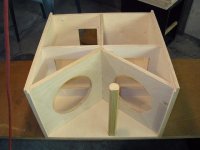
The result of these experiences was to forget all this unpredictable and difficult to repeat methods and go for the simplest solution- the most powerful linear motor on the stiffest damped cones in boxes that are very solid. Here is a pic of the double 10" box using custom driver with 95gms moving mass and optimal voice coil motor... the biggest magnet availabe. Q in box is less than 0.45 and F-box is about 30Hz. Resultant THD is less than 3% at 103dB from 20Hz to 100Hz. Seems right to me.
This electronically equalized highly damped driver/cabinet method has given the best measured performance in repeatable predictable frequency response, phase response, and maximum SPL before severe distortion onset of any system available to me for measurement to date- that would be in 30 years and many hundreds of systems of many designs. There are many that play louder with a lot more distortion and many with much poorer impulse response than can easily be achieved with this method.😀
Not sure what to conclude about what you're saying above. But this
http://i48.tinypic.com/jg1iyu.jpg
is what I was referring to earlier. I have been fortunate to see Ferrari and Mclaren TAG engines up close over the years as I have a friend closely connected with FISA. Have any pics to share of your headers?
No pics to share. Do not actually have pictures of most of the work I have done.
Twisted words... My key point was in the 1st approximation for the header volume is the concern. For the 2nd approximation length is the concern, for the 3rd term temperature is the concern, for the 4th approximation angular velocity of the gas is the concern. At the time of the discussion 1st approximation was the only item on the table.
I am in no way a transmission line expert per se but do know that suppressing all resonance in a driver mean either turning the driver into a first order system (for the first approximation) or damping a second order system until the resonance is not measurable other than by phase response. Of course extremely damped second order systems (of the first approximation again) have a response curve in the frequency domain similar to a first order system. The phase curve between first and second order systems with the same frequency response is not at all the same.
With this realization in mind, TL and the issues with achieving stable tuning seemed like a big waste of time to me just like the 5th approximation header which changes that precision tuning dependent on the direction the wind is blowing. Why not simplify and just make the driver in the box have a very low Q (stored energy) to begin with and forget about a lot of cabinet to try and correct a driver with to much stored energy (and other problems)? It was the point of the TL to suppress (dampen) the stored energy such that the driver resonance was eliminated. This is significantly different than the single frequency loading of the resonance by a tuned sympathetic resonator such as a ported system.
Ah but you say "I want to tune out the resonances by other resonators operating out of phase with the signal and/or by use of a long lossy line to absorb the energy" is the point of the TL cabinet. Well yes those are tuning methods and the resultant energy is absorbed, right? Well energy is absorbed so that is damping.
To that end lossy cabinet design proved a lot more useful in my experience and much easier to accomplish. I am not saying that for anyone else this is true. Just my experience. In the past cabinets and damping have been created such that the driver in a small cabinet with "special" damping characteristics did not change its resonant frequency when installed, less than 5% and Q was raised about 10%. This was accomplished both by variable air mass loading and lossy damping. The same driver in the same cabinet without the air mass lossy damping should have had a box resonance 1.8 times the free air resonance by the Theil Small- Lea & Lampton methods.
Further, making this work with larger (bigger that 6 .5 inches) drivers was not so easy to achieve and the lossy damping was unstable because of the large size.
The result of these experiences was to forget all this unpredictable and difficult to repeat methods and go for the simplest solution- the most powerful linear motor on the stiffest damped cones in boxes that are very solid. Here is a pic of the double 10" box using custom driver with 95gms moving mass and optimal voice coil motor... the biggest magnet availabe. Q in box is less than 0.45 and F-box is about 30Hz. Resultant THD is less than 3% at 103dB from 20Hz to 100Hz. Seems right to me.
This electronically equalized highly damped driver/cabinet method has given the best measured performance in repeatable predictable frequency response, phase response, and maximum SPL before severe distortion onset of any system available to me for measurement to date- that would be in 30 years and many hundreds of systems of many designs. There are many that play louder with a lot more distortion and many with much poorer impulse response than can easily be achieved with this method.😀
Attachments
I've been thinking, and I'm not sure about this. In fact, I might be swayed to believe that a TL deisgn in a real room just might be a good thing (contrary to my previous point of view, which did not see any advantages). Rooms at LFs are resonant with sparce modes, generally widely spaced. If a TL were done such that it fit its modes in between the rooms modes and they were damped at about the same rate as the room modes, then this would act so as to make the room appear to be larger - modally. This could be a good thing, but there are several "ifs" involved. If I get the chance I'll model this in my room models and see what happens. In all likelihood however, I won't get the chance🙁..
Being spectacularly un-qualified to contribute to the substance of this thread, I'll just kick in on this point. Richard Lord wrote an article in the late 80s/early 90s for HiFi News along the lines Earl mentions. It was a DIY piece, matching a built-in TL sub to the room in which it was used. I had the article but haven't been able to find it (Planet 10 probably has it). RL shortly afterwards went on to form REL, the UK sub manufacturer.
Okay, I'll just sit quietly from now on.
Some numbers to chew on....
For those skeptics amongst us.....🙂 - and where would we be without skeptics - a very dull world, I'm sure.....Try this exercise:
1) Take a particular frequency like 20Hz to be your driver's Fs - calculate the quarter wavelength - 168 inches.
2) Then take the next 5 multiples of that Fs and calculate their wavelength:
85 inches, 56 inches, 42 inches, 34 inches, 28 inches
-Why just the next 5 multiples - because the effect of the driver's energy storage behavior diminishes asymptotically in this region and because we anticipate damping the frequencies significantly higher than 100 hz within the transmission line since they are both out of phase with the front wave and easily localizeable.
3) Now calculate the average distance of each odd ordered peak contained in the line from the driver down to the terminus. Why odd ordered? Because we're interested in harmonics that produce pressure above or below atmospheric at the driver and terminus - not those in equilibrium with the environment. If you do this, you should wind up with an average distance from the driver of all wave peaks of approximately 105 inches. Now, if you account for area under the curves (the fundamental being the most significant contributor), it's easy to see how this number gets expanded to 112 inches or 1/6th the Fs wavelength. And 1/6 th corresponds to 60 degrees phase of the fundamental or a pipe frequency of 30 hz. For those ultra skeptics among us (god bless'em 🙂), you're free to devise a computer program that calculates the infinite sum of the acoustic wave equation for however many harmonic multiples you'd like - I suspect you'll zero in on 112 inches for an Fs of 20hz.
If you consider advancing the pipe frequency down to 20hz, it's fairly easy to see how these harmonics (3 and 5th) would get needlessly attenuated when they really need to be "amplified" (actually technically speaking, less damped than all other frequencies significantly above the resonance curve). Does this mean every driver will benefit the same if we apply the "sixth wavelength" rule? No, not hardly. High q (Qts) drivers don't have as much energy storage in freqency bands from the 3rd harmonic up. Will they benefit? Absolutely, but not as much. On the flip side of that argument you have the issue of compliance volume and the need to build a transmission line with sufficient volume for a low q driver to "breathe". Achieving critical damping with high Vas drivers requires volume. Resistive loading (stuffing/pipe taper) aren't going to allow you to reach critical damping without the obvious penalty of energy loss.
I followed what you said pretty well but it would be very beneficial to me, and presumably to others, to see something more graphical. Would it be possible for you to choose a driver, design a line based on these theories, then model that line and show us graphs predicting the line's performance? You know, "a picture is worth a 1000 words". If you can do that, perhaps you could also design/model a line that's based on the theories many of us use that you disagree with, so we could have side-by-side graphical comparisons?
Paul
Paul
There is also a similar agruement. Whether the difference is noticeable or not.😀Double blinded driving test maybe?😎
Finally, a true genius has ascended.🙂
... aside from that bit of humor recognition ...
Note to the moderators:
A bit of credit is somewhat due to this very thread for forcing some of us non-engineers (who are just as smart, and can get this stuff quite readily, once exposed to it, but not as well educated from the outset) who have been turning much of this same information over and over in our heads while still trying to grasp beyond the basics, to read further into the subtleties of what has previously been published.
I have to admit that I have a better understanding of quarter wave theories, than ever before this discussion.
Please, do NOT shut this down.
Last edited:
I am quite interested. Have you already something designed using this method? Or are you in the process of designing something using this approach?
I have a current project under construction that utilizes lessons I've learned about TL's over the past 27 years. A picture of a portion of it in very early preassembly stage is on the HT Guide site. It's name is Merlin 3TL. Unfortunately, I cannot give any further details on it right now until I reach an agreement with a new business partner. If it actually goes into production, I would be more than happy to go over fine details with you.
The point I've tried to make is - this is not rocket science. Truly, it really doesn't have to be very complicated unless there's a desire to make it so. To me, everyone connected with speaker design should be intimately familiar with the principles I've been expounding on here. It kind of shocks and saddens me how reliant many of us have become on software models to do our thinking for us. This is not to say that all software tools and models are bad for our health. They just shouldn't be used as a substitute for our knowledge of the details. Good for doing repetitive calculations? - absolutely. A substitute for critical thinking with regard to physics, acoustics, and optimization? - yeah, right. The old saying about computers is as true today as the day it was minted - garbage in, garbage out.
Your assumed driver has an fs of 20 Hz.
You calculate a quarter wavelength of 168 inches for 20 Hz and then the wavelengths for 40 Hz, 60 Hz, 80 Hz, 100 Hz and 120 Hz. These frequencies are both the even and odd harmonics of 20 Hz and assume a constant cross-sectional area for the entire length. After some verbal explanation you somehow determine the optimum TL line length is 112 in. If the TL is 112 in long then the resonant freqeuencies are 30 Hz, 90 Hz, 150 Hz, and the rest of the odd harmonics again assuming a straight TL.
A driver with an fs of 20 Hz is optimal in a TL tuned to 30 Hz? None of the frequencies associated with 20 Hz will play a significant role for this TL length.
Is this for any driver with an fs of 20 Hz independent of the rest of the T/S parameters?
What is the cross-sectional area of the TL?
There is really not much presented to assess if you design recipe has any merit.
Your assumed driver has an fs of 20 Hz.
You calculate a quarter wavelength of 168 inches for 20 Hz and then the wavelengths for 40 Hz, 60 Hz, 80 Hz, 100 Hz and 120 Hz. These frequencies are both the even and odd harmonics of 20 Hz and assume a constant cross-sectional area for the entire length. After some verbal explanation you somehow determine the optimum TL line length is 112 in. If the TL is 112 in long then the resonant freqeuencies are 30 Hz, 90 Hz, 150 Hz, and the rest of the odd harmonics again assuming a straight TL.
A driver with an fs of 20 Hz is optimal in a TL tuned to 30 Hz? None of the frequencies associated with 20 Hz will play a significant role for this TL length.
Is this for any driver with an fs of 20 Hz independent of the rest of the T/S parameters?
What is the cross-sectional area of the TL?
There is really not much presented to assess if you design recipe has any merit.
If the explanation provided is too confusing for you Martin, just draw pressure waves on graph paper and plot where the quarter wave peaks are as a function of distance from the driver.
More importantly, you keep talking about a reflected wave off the open end of a pipe as if both ends were closed off. The only way you can get a reflection of a sound pressure wave is with a substantial shift in density. Since no density shift exists to support that theory - I'm not sure we can have a meaningful, productive conversation. I've provided a link to a Meyer Sound webpage in the HTGuide thread of this conversation to provide a factual basis for this claim. The reference cited clearly demonstrates that variations of sound density and pressure are extremely small - even with very, very high sound pressure levels. These very high pressure sound level waves pass through one another unaffected. This flies in the face of your claim that somehow, there's an analogy to terminated electrical lines where an "impedance mismatch" occurs. In point of fact, there is no such analogy to acoustics. Your electrical model breaks down here. It simply doesn't apply. There is no physical phenomenon or property supported by experimental evidence to support it. For reference, once again, I'm posting the Meyer Sound Link here. It's figure 3.
Can Line Arrays Form Cylindrical Waves? A Line Array Theory Q & A
Quoted text from Meyer Sound Lab:
"Unlike shallow water waves, which are non-linear and can combine to form new waves, sound waves at the pressures common in sound reinforcement cannot join together: rather, they pass through one another linearly. Even at the high levels present in the throat of compression drivers, sound waves conform to linear theory and pass through one another transparently. Even at pressure levels of 130 dB nonlinear distortion is less than 1%."
Look at the picture Martin. Do you see any evidence that one wave train is reflecting or otherwise adversely affecting the other?
What kind of pressure (hence density) shift are you implying at the open end of a pipe that would create wave reflection at selective frequencies? What is the physical manifestation of such a claim? Is there some evidence to support a pressure differential substantially higher than 130db that would produce a density shift at the open end of the pipe? If so, why aren't all frequencies reflected instead of just standing waves (even ordered multiples of the driver's Fs)?
you keep talking about a reflected wave off the open end of a pipe as if both ends were closed off. The only way you can get a reflection of a sound pressure wave is with a substantial shift in density.
Mr JSP,
The reflection occurs because of the change of acoustic imedence at the terminus. If there was no reflection their would have no resonance, no harmonics to kill, and the pipe would not be a quarter wave resonator.
Here is a reference for you:
And a bit quoted from the page: The Open Door Web Site : IB Physics : Waves : Resonance in Air Columns
At the closed end, waves are reflected with a phase change of 180°, there is no displacement: a displacement node exists at the closed end.
At the open end, the air is free to move; waves are reflected with no phase change so a displacement anti-node exists at the open end.
Googling "resonance in pipes" will turn up a large number of references that say the same thing.
dave
...why aren't all frequencies reflected instead of just standing waves (even ordered multiples of the driver's Fs)?
I'm hardly qualified to comment technically, but isn't that kind of the definition of standing waves?
... More importantly, you keep talking about a reflected wave off the open end of a pipe as if both ends were closed off. The only way you can get a reflection of a sound pressure wave is with a substantial shift in density. Since no density shift exists to support that theory - I'm not sure we can have a meaningful, productive conversation. ...
Referring back to the title of this thread - "Real Expert or Just Self Proclaimed" - the above quote is proof positive, if such were needed, of which camp you fall into. You clearly know as much about acoustics as you know about telegraph cables and automotive exhaust systems. You also claim:
... I have an extensive background in laser design, electrical engineering, acoustical engineering, linear control theory, and quantum mechanics ...
I am impressed, sir. You are clearly a person of advanced intellect and knowledge. I am not worthy to debate with you.
- Status
- Not open for further replies.
- Home
- Loudspeakers
- Multi-Way
- Real Expert or Just Self Proclaimed