My question is one of interest to my amp designs,
What is the optimum gain setting for a chip amp?
How can one determine with electrical testing?
Or does this gain more affect the dampening of the amplifier?
It is also specific to speaker types and loading?
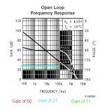
Obviously, too much will give rise to phase shifts at high frequencies. Too little is also unstable to the amp. The LM3886 chart attached shows acceptable application from gains of 11 (green) to 60 (red line) for the audio range of 5hz to 100khz. Cyan line is the typical noted 21 gain (blackjack!).
in an unrelated thread... Ratza noted
"Put a step/rectangular signal at the input and the oscilloscope on the output. I doubt you'll like the oscillations. What do you think about the open loop frequency graph at the page 16? Phase margin will be only 30 degrees."
But, I have a hard time using pulse waves to determine amplifier optimums. The wave is DC with high frequency and the bends, both outside the bounds of the normal audio bandwidth. The ringing in the transitions may be more related to the power supply rails keep up the instantaneous current draw of the amplifier.
I have tested gains of 21 (26.4 db) and 11 (20.8db), but find musically that the lower gain provides better control over speakers with the LM4766 chip amp (tested Klipsch, Hartley 300's, and custom built Seas). I also choose gain of 11 because my old school sound craft preamp put out +/-6 volts. The lm4766 chip actually has a little better phase margin, flat to 200khz @ gain of 30db compared to the lm3886.
For this range of gains, is the optimum related to chip type?
Digest this and let's see how one would best approach a test plan...
What is the optimum gain setting for a chip amp?
How can one determine with electrical testing?
Or does this gain more affect the dampening of the amplifier?
It is also specific to speaker types and loading?
Obviously, too much will give rise to phase shifts at high frequencies. Too little is also unstable to the amp. The LM3886 chart attached shows acceptable application from gains of 11 (green) to 60 (red line) for the audio range of 5hz to 100khz. Cyan line is the typical noted 21 gain (blackjack!).
in an unrelated thread... Ratza noted
"Put a step/rectangular signal at the input and the oscilloscope on the output. I doubt you'll like the oscillations. What do you think about the open loop frequency graph at the page 16? Phase margin will be only 30 degrees."
But, I have a hard time using pulse waves to determine amplifier optimums. The wave is DC with high frequency and the bends, both outside the bounds of the normal audio bandwidth. The ringing in the transitions may be more related to the power supply rails keep up the instantaneous current draw of the amplifier.
I have tested gains of 21 (26.4 db) and 11 (20.8db), but find musically that the lower gain provides better control over speakers with the LM4766 chip amp (tested Klipsch, Hartley 300's, and custom built Seas). I also choose gain of 11 because my old school sound craft preamp put out +/-6 volts. The lm4766 chip actually has a little better phase margin, flat to 200khz @ gain of 30db compared to the lm3886.
For this range of gains, is the optimum related to chip type?
Digest this and let's see how one would best approach a test plan...
Attachments
Square wave testing can be useful, if you low-pass filter the amp input (between the amp input and the square wave generator), so that the chipamp's maximum slew rate spec is not violated. (You should have a low-pass RF filter for the input of every amplifier, anyway.)
Here is a link to a thread about it. Look at my post, post # 4:
http://www.diyaudio.com/forums/solid-state/117469-square-wave-testing-slew-rate.html
Cheers,
Tom
Here is a link to a thread about it. Look at my post, post # 4:
http://www.diyaudio.com/forums/solid-state/117469-square-wave-testing-slew-rate.html
Cheers,
Tom
Data: Some designs with LM1875 can be used at up to gain 45.
Opinion: Other power op-amps may be similar; however, the influence on sound may be in direct proportion to the gain factor.
Opinion: Other power op-amps may be similar; however, the influence on sound may be in direct proportion to the gain factor.
If you run a gain budget on the whole system I suspect you'll find the optimum power amp gain is in 0dB to -10dB range. Even then the preamp usually ends up attenuating line level sources.
The greater the gain in the power amp output stage, the greater the attenuation needed at the chipamp input to keep the rest of the system around optimal. How much of a problem this is will depend on the attenuation method and chipamp but, generally speaking, the lower the chipamp gain the better the SNR, the lower the nonlinear distortion, and the greater the loop gain available to correct the output. Testing should be straightforward; set a gain and do THD or IMD sweeps on the system from output powers of 10uW up to 10W. Change gain, change chip, repeat until you're satisfied with the amount of data. (If the power levels seem low, keep in mind 1mW into 90dB/m efficient speakers produces a conversation level 50-55dB at typical listening distances. With an active crossover tweeter levels are usually 10 to 20dB below total output power, hence 10uW.)
I'd be interested in seeing the results. The LM3386 is the most linear power op amp type chipamp I'm aware of. tomchr and I recently took a look (well, OK, tomchr did all the work) and found nonlinear distortion to be on the order of 0.6% below 10mW due to input stage limitations.
As you decrease or increase the gain, the amplifier performance will deteriorate one way or another. When you reach the limits it will become unstable. With the LM series that is usually the case below 10x (20 dB) or above 50x (34 dB). The recommended 21x (26,4 dB) is nearly in the middle and probably the best technical compromise. Some Forum members claim that listening tests show the best results with the 33,35x (30,4 dB) setting used on the Gaincard.
twest820 is right in mentioning that you need to look at the entire system. The best perfoming power stage may force you to set the preamp to a gain which deteriorates its performance in a way that the overall result is worse than the other way round.
The big question is, how good can a chipamp become? Most people know the Pareto effect. You achieve 80 % of the result with 20 % of the effort and every attempt to improve on those 80 % comes with a disproportionate increase in effort. If you have a reasonably well made chipamp and the performance does still not satisfy you, it is likely that you achieve a better result from a solid state amp with less effort than it takes to wrestle that last bit of performance from that chip.
testing....
Thanks to all,
I'm still digesting the info. Well, looks like I need to spend some quality time at the test bench. I hope my old professor and NCSU will allow me some time on their fine equipment.
or else just set at blackjack!, and be happy.
However, I have a whole preamp and amp stages that need some test verifications.
Cool. Have fun!Well, looks like I need to spend some quality time at the test bench.
IMO it's as important to ask how good you need it to be. System budgeting doesn't stop at the power amp; there's the passive crossover (if any), speaker, and room as well. At some point the power amp isn't the limiting factor and, from the standpoint of improving fidelity, it makes more sense to invest the effort in other parts of the system.The big question is, how good can a chipamp become?
I didn't say that it sounds bad with low gain. The trouble is that at fast transients it tends to oscillate and from what I've seen it also runs warmer (the oscillations might be one possible source). When I made the tests at work a couple of years ago, I tried gains of 13 (12k/1k), 23 (22k/1k) and 28 (27k/1k). From what I remember the sine was perfect in all cases, but rectangular showed the problems. The oscillations were damped, but the amplitude was too big for my taste.
Equipment consisted in Toellner 8952 power supply, Agilent 33220 signal generator and a LeCroy WaveSurfer 44xs oscilloscope. I'm sorry that I haven't made any oscilloscope screenshots at the time. Now I'm too lazy to dismantle the amp and measure it again.
Equipment consisted in Toellner 8952 power supply, Agilent 33220 signal generator and a LeCroy WaveSurfer 44xs oscilloscope. I'm sorry that I haven't made any oscilloscope screenshots at the time. Now I'm too lazy to dismantle the amp and measure it again.
Ratza,
I agree about the oscillations & heat. My tone circuit turned into a mHZ oscillator, and the amp chip tried to play it....nothing but heat on amp chip and zobel resistors! It filled by o-scope with top to bottom traces.
In your design, did you add hf caps at feedback and inputs. (like the pa150, c2 & 3, DIY BPA300 6x LM3886 300W audio Amplifier)
Would those oscillations on the square waves be minimized by use of ~10pf caps across the feedback resistor;
and/or 200pf caps across the +/- input to the amp chip?
twest820,
The bench testing continue... I wonder if I opened up a can of worms (more work) with this query. This should have a finite solution <see reference, ratza's footer>. I've seen this reflective task building in many a company meeting. The quiet persons go home on time!
I agree with putting more resources to the speaker end. There are more interactions/ coloration in sound with speakers, crossover, and room. Those interactions are infinite.
Last edited:
I was under the impression that the desired gain should be set so that you get max output into the load in comparison to the input Voltage while keeping the Chip within it"s SOA ??
Soa
I believe all these gains are all within the SOA.
The input voltage is flexible in these considerations, since op-amps can provide +/- 10p-p without issues.
The finer issue of chip-amp sound quality was the question, and the electrical testing results that may be indicators.
I believe all these gains are all within the SOA.
The input voltage is flexible in these considerations, since op-amps can provide +/- 10p-p without issues.
The finer issue of chip-amp sound quality was the question, and the electrical testing results that may be indicators.
Yep, but what qualifies as a solution depends on your requirements. As a starting point I'd suggest a cumulative THD+N in the source to driver signal chain of 0.05% or less. That's a fuzzy number, but a reasonable rule of thumb in audio is effects at -50dB require critical listening to notice and -60dB is difficult or impossible to hear. Since flat magnitude and flat phase is easy to obtain in electronics the design challenges are in rejection of ground bounce between components (noise) and nonlinear distortion, with chip and feedback resistor noise being secondary criteria. If you want nonlinear distortion plus noise in the overall system to be below 0.1% (-60dB) then leaving some margin for the drivers implies <0.05% for the electronics.This should have a finite solution
Applying this criteria rejects most chipamps out of hand from the datasheet. Of the remaining chips the only one I know of which satisfies this requirement at power levels of typical home audio is the LME49811. Some may feel this criteria is too stringent and some will probably object THD isn't a good choice due to second order masking and whatnot. But it remains studies have shown 0.3% IMD is audible. THD and IMD are measurements of more less the same thing, so one can be used as a proxy for the other. National's pretty good about specing IMD, but oftentimes only THD+N is available. So it can be easier to assume IMD = THD as a starting point and design with the THD figures.
practical baselines?
Approximately as good as its power circuit allows?
. . . The big question is, how good can a chipamp become? . . .
Approximately as good as its power circuit allows?
practical experiment
On-Topic Practical Experiment:
Make an amplifier that you actually like to use.
Assuming its performance is favorable, double the gain and observe. If double is too much for a given design, simply set maximum.
Although the risk of clipping is greatly increased, the output potential increases slightly as do the dynamics. Here we have a divergence between practicality and theory. While the ears will probably report that the favor-ability aspect has increased, the measuring equipment will report that the noise has increased.
Since the device is not specific to a robotics motor driver that will land a spacecraft on the moon, but rather the device is specific to music replay, then the task is to decrease the gain (down from far too much) until the "increased favor-ability" aspect to the ear, just begins to diminish, as does the harmonic distortion.
The amplifier is now "walking the tightrope" balance between ear and measuring equipment, and you have just set the optimal gain.
Well, actually this may not result in the optimal gain in some cases, but its surely a useful data point; because, when you can measure the exact borderline point where an ear can/cannot detect a change, then you've just measured something meaningful to the specific application of music replay.
Ratza,
In your design, did you add hf caps at feedback and inputs. (like the pa150, c2 & 3, DIY BPA300 6x LM3886 300W audio Amplifier)
Would those oscillations on the square waves be minimized by use of ~10pf caps across the feedback resistor;
and/or 200pf caps across the +/- input to the amp chip?
At the time I tested and also right now I only have a 220pF capacitor between chip's inputs. I placed it right on the chip pins, beneath the pcb. I haven't tried capacitors on the feedback loop.
I was under the impression that the desired gain should be set so that you get max output into the load in comparison to the input Voltage while keeping the Chip within it"s SOA ??
SOA depends on the supply voltage, the output current and the temperature. It is independent of the gain.
The overall gain should ideally be set so that you can achieve the nominal output power with the weakest source you have. Usually one tries to get away with as few gain stages as possible to maintain complexity and cost low. You would e. g. add another gain stage aka preamplifier when the necessary gain becomes so high that a single stage's own input noise becomes audible at the output. (A problem of a certain chipamp kit with preamp from China that is sold on ebay. The preamp's gain is so high that people usually complain about hiss.) In such a case you cascade several gain stages and choose the gain of each stage so that its own input noise after amplification remains below the noise floor.
Hi dukep,
Take a look at some of the chapters in this book:
ADI - Analog Dialogue | Op Amp Applications Handbook
There are a lot of things that need to be done right to get an optimal physical implementation of an audio amplifier circuit, before you can even start worrying about using the settable circuit parameters for optimization.
I don't know your knowledge/skill level. So please excuse me if you already know all of this. But in perusing the book linked-to above, you might want to initially think about, in no particular order: RF filtering of inputs/output/power connections, physical layout (star vs. shared grounding, enclosed loop areas, shielding, unwanted noise coupling, etc), and the possible addition of a parallel feedback capacitance. The book has a lot of useful ideas and nuggets of good information.
Cheers,
Tom
The best gain for any voltage feedback opamps is the minimum gain that is allowed for the opamp to still be stable (often: 1x). Higher gains will reduce bandwidth and increase distortion and noise, while lower gains will produce instability. But this optimum gain may not be what you need in your application...
- Status
- Not open for further replies.
- Home
- Amplifiers
- Chip Amps
- Optimum Gain on Chipamp