Frankly, I'm fed up with computer geeks and those who suddenly become acoustics experts after downloading a cheesy software simulation program to their laptops. It wouldn't be so bad if they kept their technical opinions to themselves - but they insist that dozens of engineers and scientists who came before them are wrong and all their work should be deleted.
Sounds like you just described the AGW IPCC/NOAA crowd🙂
Except that they are not correct. The mechanical impedance of a driver, even after it is reflected into the acoustical domain, is orders of magnitudes greater than the acoustical impedance of a damped TL (in air, acoustics is a very soft medium - not so in water). This large impedance level difference is not "matching", at least not by my deffinition, but you seem to be saying that it is. The rest of your claims are false by virtue of their relying on a false assumption of "matching".
A horn with an extremely low flare rate becomes a TL - they are certainly NOT the "reverse of one another". You stuff a TL, I stuff waveguides - not so different.
I am not clear on exactly what it is that you are claiming about TLs. They have been modeled and understood for decades as many people have pointed out. Is your claim that some Prof in Poland discovered a new concept that changes all of that? Or do you claim that there are errors in all the previous work?
SPEAK can model TLs and I'll done some work in that respect. The math in SPEAK is beyond reproach since hundreds to thousands of products have been designed with it for nearly thirty years. To say that it is wrong would be a big claim that you would have to substantiate with some real math and data - none of which have I seen as yet.
How would you define acoustic impedance Doc? Would it look anything like this:
Acoustic impedance - Wikipedia, the free encyclopedia
I think you need a little refresher on the acoustic wave equations that have formed the foundation of everything you've been working on in your career. Your statement is so utterly oversimplified, it's really quite astounding.
The mechanical "resistance" or impedance you're referring to of a driver is a static quality that only hints at the dynamic quality known as "resonance". To suggest that a TL 's acoustic impedance can have little or no effect on a driver's electrical or acoustical dynamic impedance places your commentary in a rather uninformed light - a perspective that is diametrically opposed to all recorded experimentation and data by countless individuals both in the field of acoustics and outside. I'm afraid if you are going to continue to regress in apparent knowledge any further for the purpose of being argumentative, we will have nothing further that is constructive to say on this topic. In that instance, I would respectfully ask that you bow out of this discussion and allow others with more apparent sincerity to participate and contribute.

villastrangiato,
I am only going to say this once so please heed my words.
You have come on this site to introduce ideas that do not gel with the learnings of others whom are considered well versed in the field. As far as I can see, you are the only one who holding these beliefs. I think it prudent to consider your approach more carefully. The moderation team does not look kindly on those who come on board this way. You had the same situation occur at the other site linked to. Please take that as a hint of what to expect at this site and conduct yourself in a more congenial manner.
Yes, I am rather disappointed the way others handled their part of the argument as well.
It may be best if this thread was closed. I shall consult with the others mods
It may be best if this thread was closed. I shall consult with the others mods
The above quotes tell me that like Martin King, you really don't have a clue what the optimal operating principals are for a proper transmission line speaker loading. For your information, in a lot of TL designs, the first "undesireable" harmonic multiple of the driver's peak or free air resonance is actually desireable. ... corresponds to a resonant frequency that is exactly half way between the 5th and 7th multiple - achieving maximal cancellation of both unwanted resonances.
One last comment before i'm otta hear ... as has been said, if you want an argument Monty Python has a good place.
With every peak comes a null, If you don't suppress all the harmonics above the fundemental you get ripple. Not something desirable.
dave
I'll clean a bit and you are all welcome to continue this interesting discussion.
Play the ball, not the man, there's far more to learn that way.
/Hugo
Play the ball, not the man, there's far more to learn that way.
/Hugo
If there is still confusion about how a TL speaker works then it makes sense to keep going. But the discussion must be polite and not defensive, with parties willing to learn and not become abusive. Few, if any, experts in loudspeaker design consider the TL to be a very effective use of such a large cabinet and so much wood, but I am not sure that it's clear to the masses why that is. There is certainly more than one person here who doesn't understand the details.
Well, there are always more things to learn. For me, I am trying to tangibly understand what TL brings to the table in the terms of sound quality.
From what I can see there is a lot of work involved to get some of the gremlins under control. It may be fun trying to tame them, but what do you get sound quality wise when you finish?
Since solid state amps have matured and the cost per Watt is very cheap, it would appear hard for a TL or vented design to compete with a sealed assisted design.
.
The mechanical "resistance" or impedance you're referring to of a driver is a static quality that only hints at the dynamic quality known as "resonance".
Technically this doesn't make sense, you want to be a little more precise about what it is you are saying. "Resonance" is completely defined by the mechanical impedance and there is no such thing as a "static" or "dynamic" impedance. There is only one type.
Unless you meant "resonant", which is a subjective term, but we're not talking about subjective aspects, or at least I'm not.
The paper that you referenced is not at all clear about some major things.
Last edited:
Since solid state amps have matured and the cost per Watt is very cheap, it would appear hard for a TL or vented design to compete with a sealed assisted design.
This is the key point to me, and I made it many pages back. Just give me several closed boxes (bandpass prefered) , a DCX2496, amps and some measurements. Thats the way to good LF sound quality. Anyone who has done this has come to that same conclusion.
This is the key point to me, and I made it many pages back. Just give me several closed boxes (bandpass prefered) , a DCX2496, amps and some measurements. Thats the way to good LF sound quality. Anyone who has done this has come to that same conclusion.
How would that address issues between 100-300hz? The multi subs can't be used too high without localization issues and if only eq is to be used in this upper range, it will be single point, in which case you could have used just one sub.
btw, I do agree that TL, etc is a complete waste of time WRT sound quality, although like many things DIY, that may not matter one iota to the joy and thrill of the build.
Last edited:
The high power transmission lines I was referring to were the undersea telegraph cables referenced here:
Transmission line - Wikipedia, the free encyclopedia
Which predates the acoustic "transmission line".
That's an interesting page. It also makes my point about a circuit not being considered a transmission line until it is a significant number of wavelengths long. (It says the same about an acoustic transmission line too.)
As for undersea telegraph cables, it's true enough that they could be characterised by transmission line techniques. But they were not treated as transmission lines. Little or no attempt was made to match the terminating impedances to the cable impedance.
I've probably forgotten more about telegraphy than I ever knew, having spent the first 8 years of my working life as a telegraph engineer. Although we used teleprinters (teletypes), we still had Morse sets in the storeroom for use in emergencies.
In practice, telegraph circuits (submarine or overland) were not characterised in terms of their transmission line characteristics. The lumped constants (R, L, C) of the cable as seen at the terminations were the significant parameters. These were compensated for to allow full duplex operation over a single wire (and ground return) circuit.
I think I can explain this using an audio related analogy.
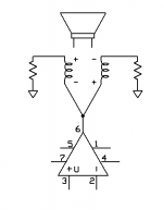
Consider the first image attached below.
It shows an amplifier attached to a dual voice coil speaker, coils in parallel, with the other ends of the coils connected to ground via resistors. The voice coils and the resistors are the same value - for example, 4 ohms. The unusual part is that the coils are wired out of phase. The currents in the voice coils are equal and opposite, so the speaker does not move.
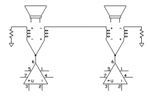
Now examine the second image. It shows two such circuits connected together. There will still be no sound from the left speaker connected to the left amp, because the currents in the voice coils are still equal and opposite. One of the 4 ohm resistors has been replaced with a 4 ohm voice coil of the right side speaker. Remember that the amplifier output terminals are virtual grounds.
However, the currents in the right side speaker voice coils are not equal, so the signal from the left amplifier will be heard in the right side speaker. Likewise, the signal from the right amplifier will be heard in the left speaker. This is full duplex operation - simultaneous signal transmission both ways on a single circuit.
In telegraph work, the amplifiers were Morse keys providing +/- voltages, and the dual coil speakers were "sounders" with dual coils. Also, real cables had significant R, L C values. These were "balanced out" by adding variable R, L and C (mostly R and C) networks to the "local" coil circuit instead of the simple 4 ohm resistor in the example.
For example, cable capacitance would cause a momentary pulse of "charging" current into the cable when the local key was pressed. The capacitance of the local side was adjusted to the same capacitance, so that the charging current of the local capacitor matched the charging current of the cable. Note that this did not alter the impedance match of the cable to the source or load, it was a process of building a local simulation of the cable's lumped RLC as seen at the cable end.
Relating all this back to the topic, a "transmission line" speaker also takes account of the "RLC" parameters of the line, and deliberately uses mis-termination to affect the characteristics of the source. I don't believe "transmission line" is the best term to describe such usage, but it is the common use term and I don't have any better suggestion to offer.
Attachments
I don't believe "transmission line" is the best term to describe such usage, but it is the common use term and I don't have any better suggestion to offer.
Yes, I would tend to agree. Its a poor terminology for what is really happening.
Hi Paul
I'd be interested to see the material you prepared and sent to <unappreciative person whose name I can't remember>.
Perhaps you could post it here? Other folks might be interested as well, and your efforts won't have been entirely wasted.
Regards - Godfrey
p.s. @ everyone else: Sorry for the lack of context.
This is a reply to a post I saw earlier which has since been deleted.
I've made statements in the past (and probably will again) that turned out to
be complete nonsense. Most of my learning on Transmission lines is microwave.
And unfortunately, air doesn't have two fields at 90 deg angles, so dominant
mode in acoustic line is a whole different animal.
Yet you got microwave engineers like John Karlson who made TL's based upon
microwave theory that sometimes DO work. The impedance match is very real.
But these have log tapered leaks between the big outside world and the line
which is much smaller.
There is a slot structure shown in one of the diagrams, as Freddi has pointed
out. But volumes trapped on either side of this leak are much too comparable.
I don't think symetrical volumes on either side of a tapered leak between lines
leads to a broadband change of impedance. I'm thinkn the volumes have to be
grossly assymetrical for that sort of tapered coupling to impart a different
impedance to each.
Now I'm one of those whackos goin' by gut here, I got no maths to prove.
But I do have a K15 that sure seems to kick far harder, and excurse far less
than it should, if all this TL impedance transformation stuff is pure nonsense.
Though I do lean toward believing the tapered slot a necessary component.
Else I'm uncertain how a horn that necks down the wrong way is supposed to
transform acoustic impedance in a favorable manner? Even if it does for some
limited range of transmission line reflections, matching won't be broadband....
In my mind, downtapered TL without tapered slot is a slightly detuned vented
box. You will need to apply fancier tricks if you want it to be more than that.
I'm open to other interpretations if they are explained well. I have no doubt
that Geddes' methods work well and are totally proven. I'm not so sure this
fact can rule out every other method as a waste of time to be dismissed...
Also relatively certain that acoustic impedance matching is a worthy goal,
and not pure fiction. I'm just not seeing anything in this paper approaches
a workable solution that would match any better than a vented box. Horns,
Karlsons, and Geddes' acoustic lever are real enough proofs that matching
works if implemented correctly.
Last edited:
Woofer subthread split off to here: http://www.diyaudio.com/forums/subwoofers/162121-woofer-digression-real-self-appointed-expert.html
dave
dave
Never seen a JK designed TL, got any details?
You mention the K15, but it's an 8th order BP, hence its narrow band of extreme acoustic efficiency.
GM
You mention the K15, but it's an 8th order BP, hence its narrow band of extreme acoustic efficiency.
GM
Godfrey:
I sent you an email via DIYaudio. I need your email address in order to send you the writeup I prepared on this subject, and I listed my direct email address for you to use.
Paul
I sent you an email via DIYaudio. I need your email address in order to send you the writeup I prepared on this subject, and I listed my direct email address for you to use.
Paul
Hi Paul
I'd be interested to see the material you prepared and sent to <unappreciative person whose name I can't remember>.
Perhaps you could post it here? Other folks might be interested as well, and your efforts won't have been entirely wasted.
Regards - Godfrey
p.s. @ everyone else: Sorry for the lack of context.
This is a reply to a post I saw earlier which has since been deleted.
Guys,
I've been "lurking" and reading this interesting post for a few days. I've also read the Augspurger paper and a bit of the King paper and found both very interesting. After years of hearing much hype I didn't realize that there was some good theory behind TL type speakers.
My question is how they compare to other designs when the variable of line damping is excercised? The undamped examples in Augsperger look essentially like vented boxes with extra resonances added. The damped versions are said to perform similarly to sealed boxes with perhaps better power handling. Proponents think that tapered versions will improve significantly over the "comparable to a sealed box" performance level. Clearly you can trade off the amount of ripple against the amount of bass enhancement. Augspurger aimed for 1dB ripple and achieved a dB or 2 of gain over a sealed system.
My question: How does a line with low damping differ from a vented box? (In its first octaves.)
David
Never seen a JK designed TL, got any details?
You mention the K15, but it's an 8th order BP, hence its narrow band of extreme acoustic efficiency.
GM
You know better. Try wings of same open area (in two stepped sections),
without log taper... Definately more than simple bandpass going on here.
There is some truth to K15 as BP, in compromise/hybrid/synergy with TL.
A good part of the length of JK's transmission line is faked with BP.
But, K15 "narrow band?" Are you sure we talking the same enclosure?
So: Ktubes, Rockets, and Klams without BP partitions to muddy the
equation are not JK designed transmission lines? Nor his waveguide
antenna? Nor his jet nozzles?
Its silly to claim you havn't seen them, cause you hang out the same
forums with Freddi, he wouldn't let you NOT have seen them.
Greets!
This is an audio forum, so was only interested in acoustic TLs, but you're right, I completely forgot about the compression driver K tubes which measure rather well, though I've yet to audition any, so no clue if they live up to it sonically. I didn't even know about them till Freddy discussed them with me ~a decade ago. Guess I had another 'senior moment', but I take exception that it's 'silly', just a sad fact of reality when you've mostly outlived your usefulness to society.
There's no TL action worthy of the name going on in the K15 unless you remove the so-called brace dividing the front upper and lower chambers to make it more like the smaller Ks. Regardless, this doesn't make them TLs, it just reduces them to 6th order BPs.
Look at Freddy's various K15 measurements, it's true gain BW is barely two octaves wide.
GM
- Status
- Not open for further replies.
- Home
- Loudspeakers
- Multi-Way
- Real Expert or Just Self Proclaimed