By itself, a 12AT7 LTP is enough to drive EL34s, if you eschew loop NFB. The 'T7 does very well, when IB = 3 mA. and 200 to 220 V. are on the plate.
By itself, a 12AT7 LTP is enough to drive EL34s, if you eschew loop NFB. The 'T7 does very well, when IB = 3 mA. and 200 to 220 V. are on the plate.
When I model this in tube cad, it puts the 12at7 in a very non-linear part of the curve.
I can model it better with a current of 15ma and a few other adjustments. Overall, the curves look better with the 6sn7 and maybe a driver, but I am pretty new at this and have little experience with either tube.
Several times I have seen these types of circuits used that are low current and in less linear areas of the curves. Am I missing something?
The 'T7 sounds very good under the conditions I gave. Its non-linearity is your FRIEND driving PP "finals". The skewing of the 12AT7 towards 2nd order products mates extremely well with the even order cancellation inherent to a PP pair. 😉
SY thanks for the feedback again. You are right. Eli thanks for your chime in as well. Your points are well taken as you are familiar with the thread and conversations on the kt88ULPP.
SY, I picked up 30dB feedback from the Mullard 5-20 design notes. I guess the big difference here is that the OP Tubes are kt-88's and not EL34's so the iron requirement goes up significantly to handle it.
I choose 105V as I plan to run a little hotter voltage than the 460 on the other thread.
The 12AT7 seems to have a good reputation in the LTP so I will try to stay at that for the moment. I have no preference for octal or 9 pin. Actually I like the look of octals better but looks don't make it sound better.
Let me work backwards. Let me arbitrarily pick 18dB of feedback.
Assuming I have the kt88 biased at 40V (number may change) and the LTP gain is 15. (tubecad stated 23.16 using a resistive tailed ltp and 12at7). I want the amp to clip from a 1 Vpeak input signal. I need a total amplification factor of 40 to drive the output tubes to clip in AB1. If my ltp gain is 15 then for NO feedback I need an input tube of 2.67 mu.
With 18dB of feed back I then need an amplification of 317.73. 18=20log(x/40). where x = amplification factor.
Again with the ltp gain of 15 the input tube would have to have a mu of 21.2.
I think thats right?????
The 'T7 sounds very good under the conditions I gave. Its non-linearity is your FRIEND driving PP "finals". The skewing of the 12AT7 towards 2nd order products mates extremely well with the even order cancellation inherent to a PP pair. 😉
Thanks Eli,. The voice of experience.😎
Eli,
In the case of the 6gk5 as the driver, using 100V or the plate and 2.5mA bias I get a voltage swing of around 130Vp-p with 5% distortion on a 2Vp-p input. Using a ccs as the anode load. The amplification factor is around 65. The mu vs. bias current also agrees when I read it correctly.
Wouldn't the combination of a large amount of 2nd in the input plus the 2nd in the ltp swing the spectrum too much?
If the t7 gain is higher like tube cad said, I am thinking that this might be a good application for something like a 12b4 which would be dynamite with its low mu. That would require only 10dB of feedback.
Last edited:
Of necessity, both LTP cathodes are at the same potential, all of the time. Those 2 will follow the signal at the non-inverting triode's grid (think cathode follower).
Spot the typo? 🙁 The blurb should read, Of necessity, both LTP cathodes are at the same potential, all of the time. Those 2 will follow the signal at the inverting triode's grid (think cathode follower).
Last edited:
I didn't catch the typo but your comment makes me verbally go through the procecs.
As the input signal rises (becomes more positive), the current in the inverting triode increases. The increased current in the inverting triode results in and increase of the AC resistance of the CCS tail which in turn raises the potential of the cathode of both the non inverting and inverting triodes. Since the grid of the non-inverting triode is AC coupled to ground, the current in the non-inverting triode decreases.
So like a cathode follower we are not fixed to an input signal within the bias voltage of the input (inverting) triode?
Last edited:
Perhaps the "best" answer is an EF86 voltage amplifier in combination with a small anode resistor.
I'm not so sure. Dropping the plate resistor like that will increase second order distortion in a stage where there's no cancellation.
I didn't catch the typo but your comment makes me verbally go through the procecs.
As the input signal rises (becomes more positive), the current in the inverting triode increases. The increased current in the inverting triode results in and increase of the AC resistance of the CCS tail...
No. The AC resistance of the CCS is already essentially infinite (compared to cathode resistance). The first part is correct, but if you think about it, the increase in inverting tube current must be exactly equal to the decrease in the noninverting side's current. If you look at the AC voltage at the cathodes, it's in phase with the input voltage to the inverting triode and 0.5 times the magnitude. That means each side has (effectively) one half the input voltage to work with (grid to cathode), which is why the gain is half that of a common cathode stage and why each side has the same output voltage, though opposite polarity.
Thanks SY and Eli,
Again your patience with me is greatly appreciated. I still have a hard time seperating AC and DC.
Your description of the gain as it relates to a common cathode makes sense.
My confusion stems(d) around the input voltage to the ltp. I had it in my head that the input signal could not exceed that of a common cathode arrangement for a given tube.
However, unlike my 12b4 preamp, the ccs is not bypassed with a cap. DUH!
If I understand correctly now, it is like a cathode follower.
So let me try an example:
For the configuration we were talking about before with the gain of the t7 LTP at 15 and the allowable output is 70Vp before clipping, then the max allowed input voltage would be 4.67Vp. The limitation here is the B+,anode resistor, and cathode resistor(or ccs) which sets the boundary. NOT being limited by driving the ltp triodes into positive grid territory as I had in my head.
Eli,
In the case of the 6gk5 as the driver, using 100V or the plate and 2.5mA bias I get a voltage swing of around 130Vp-p with 5% distortion on a 2Vp-p input. Using a ccs as the anode load. The amplification factor is around 65. The mu vs. bias current also agrees when I read it correctly.
Wouldn't the combination of a large amount of 2nd in the input plus the 2nd in the ltp swing the spectrum too much?
If the t7 gain is higher like tube cad said, I am thinking that this might be a good application for something like a 12b4 which would be dynamite with its low mu. That would require only 10dB of feedback.
FYI, CCS loading makes even mediocre triodes linear. 😉 Remember, the load line is horizontal.
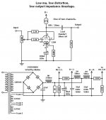
A 12B4 voltage amplifier just might do. The negative is its hunger for current. As the preamp schematic I've uploaded shows, "it's as happy as a clam" with the 100 V. of B+ available. Looks like a stack of 6 red LEDs are needed for bias. Check the 12B4 data sheet out.
Attachments
I run my 12b4 at 25mA. It is a wonderful sounding preamp. I find its sonic nature to be very nice. Not to warm and not to hard but VERY detailed sounding.
I think in this application somewhere around 25mA would be good as it would set the cathode potential to 10V and leave 90V across the tube. With its low Rp it will drive the ltp with authority (even though it doesn't need it)
I think in this application somewhere around 25mA would be good as it would set the cathode potential to 10V and leave 90V across the tube. With its low Rp it will drive the ltp with authority (even though it doesn't need it)
There are folks around here that claim an IB of 15 mA. is the 12B4 sweet spot. FWIW, the uploaded schematic is my version of a 12B4 line stage. There are more 12B4 line stage designs around than you can shake a stick at.
A stack of 6X red LEDs gets us very close to 10 V. and avoids a cathode resistor bypass capacitor. If you use a resistor to obtain the bias, the cap. can't be avoided. 🙁 The loop NFB has to have a low impedance path to the cathode.
A stack of 6X red LEDs gets us very close to 10 V. and avoids a cathode resistor bypass capacitor. If you use a resistor to obtain the bias, the cap. can't be avoided. 🙁 The loop NFB has to have a low impedance path to the cathode.
Feed Back Calculation Help
Please bear with me, this is my first attempt at calculating an approximate feedback resistor value. I would appreciate feedback if my calculations are close. The attached schematic is the amp I am working on. You are welecome to comment on that as well.
In this case the input triode is a 12b4 mu=5.5 biased at 25mA (not final but good enough for this example, Eli suggested 15mA which is okay but not for this calculation )
The LTP is a 12at7 with and effective amp factor ( per tubecad ) of 23.
For the moment lets assume that the kt88 will be biased at -55V. I want the grid to be driven +/-55V at a peak input voltage of 1V. So I need a gain of 34.81dB or amplification factor of 55.
With the 12b4 and t7 ltp my open loop gain is 126 or 42dB. To bring the gain down to the required level I will need 7.23dB of feedback.
Per Eli's comment, with the 12b4 the feedback loop will be of low impedance. I chose a 10R resistor under the LED string. That impacts the bias by .25V which may be too high but I used it since the bias point for the tube is 10V.
For 7.23dB of feedback I would need to inject .41V into the cathode.
If the amp puts out 60W for a 1Vpeak, and I take the feedback from the 16ohm tab (I would have about a 31V swing at that point. With the 10R resistor in the cathode I would need a feedback resistor of approximatley 760R. (I have 1000R in the schematic as a placard holder)
Is this reasonable?
Attachments
A better fit yet for the circuit may be a 6DJ8 instead of the 12b4. The 6DJ8 with 33mu Allows for a little more feedback at a higher impedance. In addition it looks quite linear in the region of 100V
A better fit yet for the circuit may be a 6DJ8 instead of the 12b4. The 6DJ8 with 33mu Allows for a little more feedback at a higher impedance. In addition it looks quite linear in the region of 100V
Yet more suitable (IMO) is the 12BH7, whose sections are separable. Refer back to the "main" thread. CCS loading should get close the 16X gain. Gain > the 12B4, but not excessively so, seems good to me.
Never forget that CCS loading yields pretty linear operation in all sorts of setups.

- Status
- Not open for further replies.
- Home
- Amplifiers
- Tubes / Valves
- Need Help understanding a triode fed LTP.