Hi Lynn, all,...2) What jumps out at me is the region from 700 Hz to 2 kHz is elevated 5 dB compared to the treble and much of the rest of the range. This is a crossover design error, and will dramatically affect the balance of the entire system. You don't have too little bass, your mids are too hot!...
Your conclusions are very interesting.🙂
Also to note that there is a problem of adjusting the xover instead of a ill designed one. The work they did at Madi should be a starting point for a more integrated version with the speakers/room/drivers/xover-components. Now let's check some points (forgetting for now issues with Amp/Sub/Room/and Box).
I looked at the JBL and it has a peak at around 900/1KHz of about 3/4 dBs. 15" JBL 2235H woofer
Now we look at the tweeter at Morel Morel MDT-37 (Morel) and it shows F3 at about 1500Hz.
But we look at the tweeter at PE Morel MDT-37 (PE) and it shows their F3 at about 900Hz.
So whoever is right there is a problem of design that needs to be adjusted of the summation of the 3 drivers JBL/MDT/Audax at this point and their more or less steeper xover slopes.
Last edited:
Hi Lynn
Agreed with one caveat. I like to be down about 2 dB at 10 kHz and up about the same, maybe a little more at 20-30 Hz, but it's not a linear slope. The LF rise starts at about 200 Hz and the HF fall at about 2 kHz. Between 200 and 2 kHz I like to see it pretty flat. (This is in-room of course.)
Agreed on the 1 meter thing. A lot of people here get this wrong. Worse is the guys who measure a horn in the mouth. That's really ridiculous.
I'm on board with that. The ideal curve almost looks like a pale shadow of the RIAA curve, although with different inflection points and much less overall EQ.
Getting the midrange flat is something that even the high-end boys seem to get consistently wrong - they just don't seem to be aware that hearing sensitivity to response deviations is much more acute in the midrange, and that's where the serious attention needs to go. Midrange Wrong = Everything Else Wrong (in subjective terms).
I also would like to see a restoration of sliding-inflection Bass and Treble tone controls on electronics, but admit that might be a very long wait.
Last edited:
I'm on board with that. The ideal curve almost looks like a pale shadow of the RIAA curve, although with different inflection points and much less overall EQ.
Getting the midrange flat is something that even the high-end boys seem to get consistently wrong - they just don't seem to be aware that hearing sensitivity to response deviations is much more acute in the midrange, and that's where the serious attention needs to go. Midrange Wrong = Everything Else Wrong (in subjective terms).
I also would like to see a restoration of sliding-inflection Bass and Treble tone controls on electronics, but admit that might be a very long wait.
Lynn,
I have two L-Pads still installed in the cabinet (although not wired up). When I first built the cabinets they were hooked up to a generic crossover, but when I adopted the Madisound designed crossover and recommended Audax mid I simply left them (the L-Pads) in the cabinet. I could easily use one of those or, as you suggested, wire it out so I could remotely operate it to dial down the mids.
However, I think that is only one of the problems with the design and the mids in particular.
I like the woofer, but the response curve of the upper end of the midrange does not appeal to me. The Morel tweeter is not so bad, but the crossover point is still in the 3,000 Hz range, which is where the midrange gets unruly. I can see from the LEAP design that they did try to give it a steeper slope to avert some of that.
My question is, would it be better served to consider a different midrange driver (and perhaps a tweeter if required) to clean up the response before and after the second crossover point?
I understand that this also implies a respin of the crossover, but I have a lot of effort invested into these and I would rather get the project right than compromise for the sake of throwing in the towel.
What I am asking is, what are my options? I am sure that there are many, but I would like to see if there are other options that I am not thinking of or maybe this whole endeavor is the wrong path, too?
I don't mind making mistakes because I learn. I do mind repeating them, although. 🙂
Very difficult questions you ask. You are the owner you should (must) know the answers to some of them....However, I think that is only one of the problems with the design and the mids in particular.
I like the woofer, but the response curve of the upper end of the midrange does not appeal to me. The Morel tweeter is not so bad, but the crossover point is still in the 3,000 Hz range, which is where the midrange gets unruly...
My question is, would it be better served to consider a different midrange driver (and perhaps a tweeter if required) to clean up the response before and after the second crossover point?
...What I am asking is, what are my options? I am sure that there are many, but I would like to see if there are other options that I am not thinking of or maybe this whole endeavor is the wrong path, too?
I don't mind making mistakes because I learn. I do mind repeating them, although. 🙂
Now, (1) what I see that is wrong on the original xover to start with, the tweeter phase is wrong between the + and -, so it should be inverted from the one of the Mid (ok). That is affecting the mid region a lot, unless you have it right. I'm saying this with the idea that we still have the same xover, note that it can be different later. Now I'm working with what you have.I understand that this also implies a respin of the crossover, but I have a lot of effort invested into these and I would rather get the project right than compromise for the sake of throwing in the towel.
(2) In a quick look, you ban benefit from a LRC (series) on the woofer line (parallel to the woofer) for better impedance with Amp, that you can add later:
L=22mH
R=6,8 Ohm
C=220-333uF
(3) I bet that the right output curve from the Morel is the one from PE/LDSG, and that the one from Morel is wrong, because decay starts at ~2KHz more in line with Fs=700Hz and MDT37 waterfall.
(4) Only you can decide
 if you like the
  from the Audax, or that you can make it sound good (/or that it deserves the effort, since you have it already).
(5)
Yes, it looks like it in a good way.I can see from the LEAP design that they did try to give it a steeper slope to avert some of that
(6) The problems you find at 5-10KHz region is from an anti-phase between the tweeter and the Audax. (when you have them reversed like I said that they should be, in this case). Needs to be worked out.
(7) Did you mention size of the box for the mid?
(8 and last) I would concentrate on the Audax... like someone said.
Last edited:
Very difficult questions you ask. You are the owner you should (must) know the answers to some of them.
Now, (1) what I see that is wrong on the original xover to start with, the tweeter phase is wrong between the + and -, so it should be inverted from the one of the Mid (ok). That is affecting the mid region a lot, unless you have it right. I'm saying this with the idea that we still have the same xover, note that it can be different later. Now I'm working with what you have.
(2) In a quick look, you ban benefit from a LRC (series) on the woofer line (parallel to the woofer) for better impedance with Amp, that you can add later:
L=22mH
R=6,8 Ohm
C=220-333uF
(3) I bet that the right output curve from the Morel is the one from PE/LDSG, and that the one from Morel is wrong, because decay starts at ~2KHz more in line with Fs=700Hz and MDT37 waterfall.
(4) Only you can decide
(5)Yes, it looks like it in a good way.
(6) The problems you find at 5-10KHz region is from an anti-phase between the tweeter and the Audax. (when you have them reversed like I said that they should be, in this case).
(7 and last) I would concentrate on the Audax...
Yes, the crossover is still the same. So, I should invert the phase of the tweeter. I can do that and rerun my plots. Good catch.
Your point #4 appears to be adding a Zobel network for impedance compensation?
#7 - The box is sealed and has a volume of about 0.24 cubic feet. Madisound was given that data before starting the design.
#8 - What do you mean by concentrating on the Audax? Do you mean that the problems (after correcting the tweeter phase) are now predominantly with the mid?
Last edited:
Very difficult questions you ask. You are the owner you should (must) know the answers to some of them.
Now, (1) what I see that is wrong on the original xover to start with, the tweeter phase is wrong between the + and -, so it should be inverted from the one of the Mid (ok). That is affecting the mid region a lot, unless you have it right. I'm saying this with the idea that we still have the same xover, note that it can be different later. Now I'm working with what you have.
(2) In a quick look, you ban benefit from a LRC (series) on the woofer line (parallel to the woofer) for better impedance with Amp, that you can add later:
L=22mH
R=6,8 Ohm
C=220-333uF
(3) I bet that the right output curve from the Morel is the one from PE/LDSG, and that the one from Morel is wrong, because decay starts at ~2KHz more in line with Fs=700Hz and MDT37 waterfall.
(4) Only you can decide
(5)Yes, it looks like it in a good way.
(6) The problems you find at 5-10KHz region is from an anti-phase between the tweeter and the Audax. (when you have them reversed like I said that they should be, in this case). Needs to be worked out.
(7) Did you mention size of the box for the mid?
(8 and last) I would concentrate on the Audax... like someone said.
Rereading one of your earlier posts I think I am answering one of my questions. It looks like Madisound has essentially pointed me down the path with the work I contracted them to do.
This is not a finished design, but the start-point for me to fine tune the design.
So, step one is to invert the tweeter phase and see what I get after another sweep.
Step two will probably be focused around the mid and its crossover so that the mid better matches the other drivers.
Step three would be further refinement of the box and crossover and adding impedance compensation for the woofer as required.
Step four would be a final evaluation to see if I am really done or if I determine that I need to do more work on the system.
1. approach:
Woofer: in phase (as in LEAP xover), apply LRC if you want later.
Mid: inverted phase (as in LEAP xover), duplicate L=.75mH to ~1.5mH, duplicate C=8uF cap to ~15uF. Take out 12R resistor, from this leg.
Tweeter: inverted phase (as in LEAP xover), change xover from 2order to a 3order to make phase correct and benefit from slope to tweeter. In the place of the C=8uF cap, I would have ~10uF (bigger) and a C=4,7uF extra cap after the leg of the inductor to the tweeter (look at a 3.order xover T). That's a starting point for your new xover, at the same time listen to your mid (phases should be correct) and improve performance for the woofer and listening room.
You will have now something like this:
(Probably next/later you need to lower/adjust xover point for the woofer...)
Attachments
Last edited:
1. approach:
Woofer: in phase (as in LEAP xover), apply LRC if you want later.
Mid: inverted phase (as in LEAP xover), duplicate L=.75mH to ~1.5mH, duplicate C=8uF cap to ~15uF. Take out 12R resistor, from this leg.
Tweeter: inverted phase (as in LEAP xover), change xover from 2order to a 3order to make phase correct and benefit from slope to tweeter. In the place of the C=8uF cap, I would have ~10uF (bigger) and a C=4,7uF extra cap after the leg of the inductor to the tweeter (look at a 3.order xover T). That's a starting point for your new xover, at the same time listen to your mid (phases should be correct) and improve performance for the woofer and listening room.
You will have now something like this:
I am having a hard time wrapping my brain around what you are recommending. I am more of a visual type of person, so having a schematic is far easier for me to follow than a description of a schematic.
I will try to draw what you are stating and maybe you can tell me if I have what you are recommending correctly drawn.
(Probably next/later you need to lower/adjust xover point for the woofer...)
Ah. How much lower should that be set to? Are you thinking just tweaking that point?
I do have a theoretical baffle step response at 210 Hz, but that is too low for the mid to cross at, so I may be better with adding an active baffle step correction EQ between the preamp and power amp.
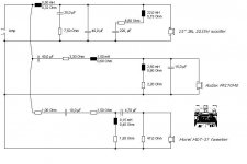
Here it is (as a 1.st approach):
Yes, that makes perfect sense. Thank you for doing that!
Woofer: If you bring the 40uF cap to 68uF you lower the slope/xover-point. For now I would not change very much.Ah. How much lower should that be set to? Are you thinking just tweaking that point?
Mid: To adjust it's output, if you need to open-up the Audax a little, reduce the 3R resistor. If you need to lower it's output, to match JBL output, do the opposite. That works for the side of the woofer only.
Woofer: If you bring the 40uF cap to 68uF you lower the slope/xover-point. For now I would not change very much.
Mid: To adjust it's output, if you need to open-up the Audax a little, reduce the 3R resistor. If you need to lower it's output, to match JBL output, do the opposite. That works for the side of the woofer only.
Thanks. Makes sense.
Hi
The polarity as shown by LEAP is correct based on my past experience on 3-way designs similar to this. I would not expect the tweeter to need a 3rd order HP because the horn loading adds its own extra pole (acoustic) near the cutoff. The best way to determine the un-correctedness is by measuring for off-axis nulls at the crossover frequency. The absence of off-axis nulls the better the design.
Before changing part values and connections, I would simply add the pad on the mid at the driver inputs and adjust to match the tweeter on-axis at 8-10KHz or so, then go 30 degrees off and sweep to verify no nulls near the crossover.
Depending on where things end up after the adjustment then you could see if the BSC inductor and or woofers LPF Q needs tweeking. Messing with the mid circuit 3R changes the bandwidth at the upper end as well as near the low end, so changing that is more work to get right.
Last edited:
It needs a 3.order for better phase matching....I would not expect the tweeter to need a 3rd order HP because the horn loading adds its own extra pole (acoustic) near the cutoff.
Dimensions of the room look they are ok for ressonances, no big issues. I would lower 1 foot on the listening area though. Nothing else besides acoustically treating the room, and move the speakers (in or) way from corners.Here are some 3-D renderings of the room, which combines a kitchen and family room. Total room floor size is 15 feet by 29 feet. Lowest ceiling is 8 feet and it rises to 12 feet at the one side.
😀
Last edited:
Hi
The polarity as shown by LEAP is correct based on my past experience on 3-way designs similar to this. I would not expect the tweeter to need a 3rd order HP because the horn loading adds its own extra pole (acoustic) near the cutoff. The best way to determine the un-correctedness is by measuring for off-axis nulls at the crossover frequency. The lower the off-axis nulls the better the design.
Before changing part values and connections, I would simply add the pad on the mid at the driver inputs and adjust to match the tweeter on-axis at 8-10KHz or so, then go 45 degees off and sweep to verify no nulls near the crossover.
Okay, take a SPL reading 2m from front at the crossover and then one at 45° (maybe some points in between as well) and look for cancellation or a big drop in SPL at the same frequency.
I would also consider just trying to roll my own crossover, but I have not done that before (3-ways being particularly complex) and I don't know if I really have the tools to do that.
1. I should actually measure the T/S parameters and I don't have a WT2 or whatever. I could try to do that the old fashion way as described by Dickason.
2. I have Bass Box Pro and X-Over Pro, but I am a little skeptical if that software would really do the job. Any thoughts?
3. I lack the acoustic data for the woofer, mid, and tweeter. X-Over Pro lacks those models' acoustic data and I am unclear how I generate that information.
I like being in control, so having control of the crossover design would be comforting and a good learning experience, but may not be financially sound if I lack a lot of tools to do the job.
Why start from scratch unless it's really broken> I think all the pieces are there it's just a matter of tweeking to get it closer to what YOU want from it in your room.
Box vent re-tuning
adjust the mid level
check for absence of off axis nulls
verify BSC and tweek woofer LPF's
Box vent re-tuning
adjust the mid level
check for absence of off axis nulls
verify BSC and tweek woofer LPF's
It needs a 3.order for better phase matching.
Dimensions of the room look they are ok for ressonances, no big issues. I would lower 1 foot on the listening area though. Nothing else besides acoustically treating the room, and move the speakers (in or) way from corners.
2nd order electrical + acoustical response is potentially a 4th order HPF
FWIW some people go with first order electrical HP and lower crossover point to take advantage or the benefits of horn loading vs flat flange designs.
Last edited:
Why start from scratch unless it's really broken> I think all the pieces are there it's just a matter of tweeking to get it closer to what YOU want from it in your room.
Box vent re-tuning
adjust the mid level
check for absence of off axis nulls
verify BSC and tweek woofer LPF's
Yes, and that's what the guy on my one shoulder keeps whispering. Then there is this other guy on the other shoulder that cries just DIY.
So, that is why I vacillate on this. Last night I thought about the whole adventure with these speakers. They have gone through four iterations of changes since I first naively slapped something together. Each time another piece of the puzzle fell together, but my biggest mistake was not building these with the iterative nature of the design process in mind. So, they have become a bit of a franken-speaker.
I could have made these so that access to the crossover was a lot easier, too. 🙂
Yes, and that's what the guy on my one shoulder keeps whispering. Then there is this other guy on the other shoulder that cries just DIY.
I could have made these so that access to the crossover was a lot easier, too. 🙂
LOL DIY never sleeps.
try to make it fun somehow
see how much you better you can make it sound without adding anymore cost other than your sweat and a couple of PVC vents and maybe a few resistor changes and a inductor or 2.
Last edited:
- Status
- Not open for further replies.
- Home
- Loudspeakers
- Multi-Way
- Why no Bass?