Thanks, I understand now. It is not a balanced out, but rather an out with distortion cancellation. But before canceling them we increase them powering anode from high-Z source. I still did not get the point.
Yep, you still did not get the point. It IS a balanced out, go figure...
Yep, you still did not get the point. It IS a balanced out, go figure...
What balances it, if anode volt/ampere characteristic is positive? 😱
Yep, go figure, 😉
The CCS forces the AC current balance (equal and opposite).
Cathodes force the DC voltage balance, and impedance balance.
You could probably drive a pushpull with something like this too...
There is Mu/2 voltage swing at plates of this long neck pair.
Which reduces gain of non-inverting cathode from 1 to 0.5
But also increases gain of inverting cathode from 0 to -0.5
The voltage attenuation may or may not be a problem.
Current gain is possible, but with only 2ma you won't get
far with the triode I've selected.
Last edited:
Since this circuit relies upon a relatively large voltage swing at the plates for a small
differential voltage swing at cathodes, it makes sense we want maximum headroom
for those plates to freely swing. I suspect that fixed bias may not be the best answer
for assuring those plates always hover at the optimum center voltage.
If one were to upgrade to Waveborn style Gyro/Servo for the long neck instead???
Now I think you got a winner for driving long differential lines and maybe as a phase
splitter that can directly drive output tubes.
Last edited:
I'm having real difficulty coming up with a Gyro/Servo of sufficient impedance.
All my simulated attempts so far have "worked", more or less... But much more
leaky than simple CCS. Has a drastic detrimental effect upon AC balance. I've
tried both Wavebourn (PNP) servo style and MJK (NPN) style, but I've probably
screwed up something in each. Perhaps my choice MJE340 MJE350 is to blame?
I tend to sim with lame oldslkool parts I know I have on hand...
Wavebourn, are you saying 2nd harmonic is reinforced rather than canceled?
I still can't "figure" how that would be, but it seems apparent in the output...
I'm still not sure it isn't the CCS acting up... I need to sim a pure CCS, and
that would probably tell me where the 2nd is coming from?
Last edited:
Hi Peter;
try to take DC feedback for gyro from cathodes through equal resistors.
To get rid of the 2'nd harmonic I would use a Concertina before this stage to drive both control grids counter-phase.
But still I would use a transformer instead. 🙂
try to take DC feedback for gyro from cathodes through equal resistors.
To get rid of the 2'nd harmonic I would use a Concertina before this stage to drive both control grids counter-phase.
But still I would use a transformer instead. 🙂
Yeah, the servo'd version is quickly getting ridiculous supporting parts count.
Wasn't wanting to litter up the field with sand, nor elevate a Pentode's heater.
Will have to settle for a stiff CCS and hope Mu sets plate voltage in the zone.
Lower Mu might help, but I own so many 6DJ8. Like I said: sim with what I got.
This isn't really a circuit I have much use for at the moment, but was enjoying
the challenge.
Concertina is a good place for sand. Into a differential pair of triodes the long
tail way. With normal voltage gain and all that. But not so easy to direct couple...
Last edited:
Hey all you smart tube guys,
I have been getting real interested in Balance Connections to amps lately. I have a Pass Aleph 5, Krell Clone, that have balanced inputs, and eventually building a Aleph JX...
Anyway, I have been shorting the neg input to ground for single ended connections, but have been thinking of this idea to build a tube pre Concertina style to balanced XLR connections - see attachment.
Is there any reason this won't work? No values are set yet, just proof on concept only. Note - I do not have a balanced source.
Thinking a 6SN7, 6922 or 6N1P Input tube...
If a horribly dumb idea, go easy on me, as I am very thenthitive.
Conceptually you're right but you'll have a hard time getting it to drive a 600 ohm load. Your configuration is good for high levels at a high impedance but +4 dBm is only 1.22V rms differential. I think a transformer would be easier though you may be able to use resistive 'minimum loss pads' on the 2 outputs to trade signal level for impedance. It's not as efficient as a transformer but it's just resistors with no hum pickup or phase shifts.
G²
I would use a Concertina before this stage to drive both control grids counter-phase.
But still I would use a transformer instead. 🙂
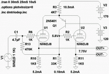
Oh!, What if emitter holds long neck plate voltage to a constant?
And use error off of a collector to countermodulate the other grid?
Might could get 1X and -1X gain off both cathodes?
Oh!, What if emitter holds long neck plate voltage to a constant?
And use error off of a collector to countermodulate the other grid?
Might could get 1X and -1X gain off both cathodes?
Like a cascode?
Sneaky Concertina with 2 cathode outputs... Looks interesting. 😉
But anyway load of the left cathode will cause higher anode swing, like in the plain Concertina...
What I meant, a Concertina before cathode followers.
Edit: Wait... Do you mean a common neck? Looks interesting. But the right side would cause a positive feedback such a way.
Last edited:
Even easier: Resistor neck, a cap from plates to opposing grid... No sand.
Its some form of paraphase now???
Not perfect, but dirt simple, and almost good as CCS.
Now to add back CCS and see if there is a synergy?
Its some form of paraphase now???
Not perfect, but dirt simple, and almost good as CCS.
Now to add back CCS and see if there is a synergy?
Last edited:
Nope, I didn't have a clue what was the theory going on in the other thread...
Just that it looked like my Fisher. I thought it was just about phase shifts???
My head was stuck on folded cascode. This is just a weird way to fold one...
(having a plate follower to do the voltage holding.)
But you are right, if this dumbs the right tube down to a voltage drop?
Then its just a folded Concertina..
Last edited:
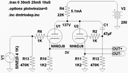
OK, latest circuit (post #35) looks interesting/promising and do-able, although (being a tube retard) I don't know why there are no DC blocking caps at both cathode outputs - isn't there 3 volts DC here? Do they somehow cancel out?
From what I an reading, using a transformer may be a bit more simplistic & better??
BTW - the Sescom MI-14 is a 150/600:150/600
From what I an reading, using a transformer may be a bit more simplistic & better??
BTW - the Sescom MI-14 is a 150/600:150/600
Last edited:
Something still not right. I'm now having a problem with cap pumping up a charge...
Right triode works as an integrator. Signal from the left cathode through the load drives right cathode causing phase shifted PFB through left anode. Without a cap a feedback was not phase shifted, but anyway it was positive one, highlighting distortions.
Hmmmm... Got most of the issues under control, and a more favorable
operating point for the 6DJ8. But I can't help thinking how to ditch the
sand???
And to answer the other's question: Yes, prolly need caps on the outs
for XLR. Keep +7.5V from getting out, keep +48 phantom from gettin in.
Whatever's on the receiving end might try to deliver power to a mike.
R1 might need parallel Zenier during startup? Thought of that too late.
Else it gonna pull the grids (and input cap) way high for no reason...
Edit: 220K in series with collector is a simpler soloution for cold start.
Attachments
Last edited:
Do the cathode impedances match this way, or am I just fooling myself?
I mean, since its a folded Concertina, are Z's different like a Concertina?
Or has going backwards thu the 2nd triode corrected that?
If its not lowering impedance, 2nd triode could be ditched and just
take signal directly off a 1K5 at the collector. DC's would be totally
different, but AC would still be phase inverted mirror images.
So, is the second tube doing something useful here or not?
Is Q1 forcing the second triode's cathode to follow as-if it
were much higher impedance (the plate impedance of U1?)
Last edited:
- Status
- Not open for further replies.
- Home
- Amplifiers
- Tubes / Valves
- Um, Can I do this?