Hi,
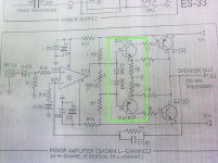
I just bought a power Amp DIY circuit recently. Just want to start to learn everything about power amp. Does the part that i quoted with a box consider a push pull amplifier?
View attachment 156387
thank you.
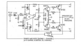
Push-pull back in the tube days (still for some) was a center tapped transformer with 2 power tubes driven 180 degrees out of phase. When 1 tube 'pushed', the othe 'pulled'. What it implies is separate devices (tubes or transistors) for the positive and negative peaks. The section you circled is the driver section for the output devices. Q1 and Q3 form a Sziklai pair which is configured to have some voltage gain since the opamp "IC" can't deliver the full voltage swing by itself. Q2 and Q4 perform the same function for the negative part of the signal. Overall gain of the amp is R4/R10 + 1. Adequate but not impressive as power amps go.
G²
That part provides current and voltage gain and drive for the outputs, and creates the required bias for the output transistors.
The output transistors are doing the "push pull" part, but there is also a "push-pull" output circuit inside the opamp.
If you want to learn everything about power amps, read some text books and everything in this forum - then you will be either expert or very crazy person? 😀
_-_-bear
PS. no need to buy "circuits" schematics - there are so many here and online.
Kits are also here and online.
Take a look in the "Pass Labs" section for some nice amps and sources of PCBs and parts... have fun!
The output transistors are doing the "push pull" part, but there is also a "push-pull" output circuit inside the opamp.
thanks for all the replies. So do u mean that Q1 and Q2 work as a push-pull?
hi,
can i say that the Op-Amp works in a way of negative feedback?
thank you.
The opamp itself works open loop, but the whole ampolifier has neg feedback via R4 and C7: a part of the output is fed back to the neg input.
BTW a good check for push-pull is to look at the two output devices. If the signal goes up, does the current through one output device increase and through the other device decrease? Yes? Then it's push-pull.
jd
this is a genuine push pull amp with an output compound pair
with voltage gain...and also vbe variation gain !! that will
lead to great themal instability...
the power devices have no base to emitter resistors that
would allow to get rid of eventual stored charges as these
device can be driven into saturation in this kind of topology,
thus allowing for stored charges to occur...
anyway, a doubtful design...
BTW a good check for push-pull is to look at the two output devices.
jd
hi thanks for the replies. BTW which two output devices do u mean?
thank you.
hi thanks for the replies. BTW which two output devices do u mean?
thank you.
Errr... The two devices that drive the output?
jd
hi thanks for the replies. BTW which two output devices do u mean?
thank you.
Q1 and Q2 are the final output devices and arfe the physically largest of the group.
G²
in the circuit from post #1 I missed follow:
1) bypass capacitor about D5(7) and D6(8) - that means no AC short there.
2) Resistors between collector of Q3(7) respectively Q4(8) and the supply rail. The idle current of Q3(7) respectively Q4(8) depends here only from the spreading base current of Q1(5) and Q2(6)
Here the URL of supplier from Spain - PCB and complete schematic also include:
http://www.escol.com.my/kits/ES-033.html
The DC protection with relais contact in series to the speaker isn't a good solution. If one provide GND refer to the neg. supply rail and the introduce of an electrolytic capacitor (top quality of course) best DC speaker protect are present. An other solution you will find in post #13 about
http://www.diyaudio.com/forums/pass-labs/160416-threshold-amps-dc-protected.html
The great advantage is, that I can check out always the newest generation of operational amplifiers (OP-Amp) e. g. the LME's from National Semiconductor about
http://www.diyaudio.com/forums/solid-state/132471-national-opamp-inflation.html
Last edited:
hi,
thanks for the replies.
Can i say that the Op Amp work as a buffer to reduce the loading of the input capacitor?
thanks.
thanks for the replies.
Can i say that the Op Amp work as a buffer to reduce the loading of the input capacitor?
thanks.
hi,
From what i read from this link, it shows a class AB push pull output.
http://en.wikipedia.org/wiki/Electronic_amplifier

As refer to circuit diagram that i posted at the first page, i just want to ask that can the circuit diagram that i posted has a push-pull output stage?
thanks.
From what i read from this link, it shows a class AB push pull output.
http://en.wikipedia.org/wiki/Electronic_amplifier

As refer to circuit diagram that i posted at the first page, i just want to ask that can the circuit diagram that i posted has a push-pull output stage?
thanks.
This schematic is a discrete op amp with a simplified push pull
output stage...
I can only advice you to make some readings in the wikipedia
section you re quoting...
output stage...
I can only advice you to make some readings in the wikipedia
section you re quoting...
That is just a basic class AB output amp, using VBE multipliers, and in that configuration its also known as a totem pole output.
It is a very basic power amp, and you will need to make sure the output transistors are all thermally close, especially the diodes. The choice of op-amp will make a massive difference in the quality of an amp like this.
It will also be a bit more sensitive to power supply variations, and wont be very good at ripple rejection.
hi,
thanks for the replies.
Can i say that the Op Amp work as a buffer to reduce the loading of the input capacitor?
thanks.
Not in this case. The op-amp is actually used as the main voltage gain. The discrete transistors are in this case a voltage gain of 1, but a very high current gain.
Its really just an op-amp amplifier with current boosted output.
The feedback is fairly essential to reduce distortion.
This amp would run without a Cin. Just make sure your output doesnt have a dc bias to it, because this amp will amplify from DC up. You could even use this as a servo amp for non audio purposes heh.
BTW, here is a diagram of a classic push pull valve amp. http://en.wikipedia.org/wiki/File:Tube_push_pull_poweramplifier.PNG
Last edited:
- Status
- Not open for further replies.
- Home
- Amplifiers
- Solid State
- Is this consider a push pull amplifier?

