Hey Zen Mod,
Must find out what a "full Suzy" is😱.
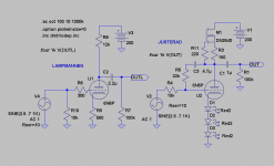
Found an error, R10 should not be DC-connected to ground. Cap should be added in series.
Must find out what a "full Suzy" is😱.
Found an error, R10 should not be DC-connected to ground. Cap should be added in series.
Supersymetry 🙂
BTW: I miss the grid resistors (grid to ground).
Franz
Hey Franz,
Yep I know of Pass Suzy(even not in detail), just couldn´t figure out how Zen Mod wanted to apply it here😱.
About the gridresistors, none are needed as the DAC is DC-connected and bias the grids to +2,5V. With over 5V on the cathodes no negative supply should be needed for the CCS.
Last edited:
With over 5V on the cathodes no negative supply should be needed for the CCS.
Maybe not for the ones with an arrow inside a circle 🙂 Who makes them?
Yes, it will work.
I used a similar circuit on my CD63 a couple of years ago.
( It's on the huge thread somewhere....)
I used E88CC at an anode voltage of 30v
Andy
.
I used a similar circuit on my CD63 a couple of years ago.
( It's on the huge thread somewhere....)
I used E88CC at an anode voltage of 30v
Andy
.
Maybe not for the ones with an arrow inside a circle Who makes them?
Will also work with a single BJT CCS. With over 5V DC and a signal of under 1V no problems will occur😉.
I used a similar circuit on my CD63
Finally found your amp and found it farfetched to call ours alike🙂. But sure, you used two triodes and took the output signal from one of them. Maybe you changed the circuitry later in the thread as the one I found looked rather basic. Can you show it again?
Last edited:
Will also work with a single BJT CCS. With over 5V DC and a signal of under 1V no problems will occur😉.
Finally found your amp and found it farfetched to call ours alike🙂. But sure, you used two triodes and took the output signal from one of them. Maybe you changed the circuitry later in the thread as the one I found looked rather basic. Can you show it again?
Yes, the diagram on the thread is basic, to say the least !!
The input was modified from T-L's published circuits and the triode stage was better developed, of course.
Sorry, I can't be more explicit at the moment ... most of my stuff and the final stage is in storage.
Andy
.
Bastard, anyone? - DIYAudio.rs - Page 6
front end for Juma/ZM Bastard Circlotron , asked by Stein
front end for Juma/ZM Bastard Circlotron , asked by Stein
An externally hosted image should be here but it was not working when we last tested it.
Last edited:
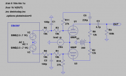
Was wrong about calling it "instrumentation amplifier", should be "differential amplifier"! Zin is R1+R2.
Attachments
![differ[1].PNG](/community/data/attachments/162/162126-bc8b6fb7a7bf81403ddcfa7657298f6b.jpg?hash=vItvt6e_gU)
Last edited:
With over 5V DC and a signal of under 1V no problems will occur😉.
I am very curious if anyone has taken measurements in support of this. My understanding is that most current sources underperform at drops less than 15-20v. Something to do with non-linear capacitances of the junctions.
I am very curious if anyone has taken measurements in support of this. My understanding is that most current sources underperform at drops less than 15-20v. Something to do with non-linear capacitances of the junctions.
Have heard that MOSFETs should have an ample voltage margin. These are also known to have high capacitances all over😀.
Have though seen quite a few single smallsignal-BJT CCSs used down to something like 3-4V.
Zen Mod,
Where is the unbalanced output😉?
use one , ground another
Interesting, will try it when I get home but I have my doubts. But I guess you have tried it.
By grounding I suppose you mean a capacitor from anode to ground.
By grounding I suppose you mean a capacitor from anode to ground.
tried or not - that's usual praxis in pro electronic - when using full balanced stage , as bal/unbal or unbal/bal convertor .
just imagine XLRs on both sides ; with tying one leg to gnd , you get that side ( either input or output ) as unbalanced ; other side is still balanced .
depending on circuit , some even aren't functional , if unused leg isn't tied to gnd
just imagine XLRs on both sides ; with tying one leg to gnd , you get that side ( either input or output ) as unbalanced ; other side is still balanced .
depending on circuit , some even aren't functional , if unused leg isn't tied to gnd
Sorry Zen Mod,
What I found out wasn´t very convincing. The one I proposed first will be the one to go for. Don´t care what praxis is in pro electronics, this is hifi😎.
What I found out wasn´t very convincing. The one I proposed first will be the one to go for. Don´t care what praxis is in pro electronics, this is hifi😎.
I didn't told you to do anything ; I just bring examples .
that stage I posted is , in fact , pretty generic one , without too much efforts in squeezing last % of finesse . if I tried to do that - you would see gyrators in anodes .....
just a question - did you simmed it , or tried in vivo ?

that stage I posted is , in fact , pretty generic one , without too much efforts in squeezing last % of finesse . if I tried to do that - you would see gyrators in anodes .....
just a question - did you simmed it , or tried in vivo ?
- Status
- Not open for further replies.
- Home
- Amplifiers
- Tubes / Valves
- BAL to UNBAL DAC buffer