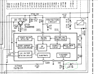
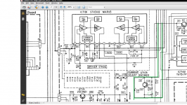
I have a Luxman L435 and I just put all new electrolytic capacitors in it. I managed to hit exact values for all of them except one, the little 0.47uf 50V cap as cicled in green on the attached schematic close-up. Capacitor C7113.
I didn't have that exact value but put in 1.0uf 50V Nichicon KW as it's the closest I had on hand. I DO have a 0.47uf 100V polyester Wima MKS2 as the only exact value for that on hand.
Question: Do I leave in the now new 1.0uf 50V Nichicon KW or use the polyester? [golf pants ]
]
Thanks!
Schematic capture:
I didn't have that exact value but put in 1.0uf 50V Nichicon KW as it's the closest I had on hand. I DO have a 0.47uf 100V polyester Wima MKS2 as the only exact value for that on hand.
Question: Do I leave in the now new 1.0uf 50V Nichicon KW or use the polyester? [golf pants
]Thanks!
Schematic capture:
Attachments
Check out the TA7317P's datasheet. Looks like this value is not that critical. I'd keep the 1uF 😉
Thanks! I have left in the Nichicon KW 1.0uf 50V there. I was worried if it was part of an RC filter for a filter of critical nature like low pass or high pass.
So...All the electrolytics are changed, circuit board inspected and cleaned. I cleaned all the Alps PCB pots with contact cleaner and followed up with Deoxit Faberlube. They feel nice and smooth now.
Capacitors all from Digikey: Panasonic THA 105 degree 15000uf for main filter caps. Oddly, the Panasonics have a stated ESR the same as a Mundorf. 😎
2 of those for $25 and all the other capacitors, Elna Silmic II's and Panasonic FC's came to another $25 so not too bad of a hit, yet. A worhty investment so far, on top of the $50 to buy the amp in the first place.
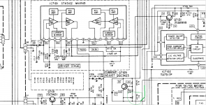
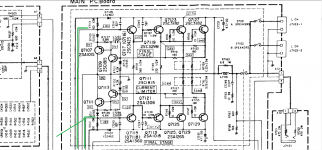
Anyhow, before I fire it up I read through Saki's vintage amp tutorial and with regards to my Luxman L-435 there are two variable resistors, VR7101 AND VR7102.
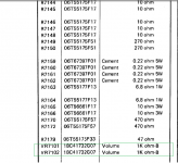
Question for those more knowledgeable than me: Are these two variable resistors [1K volume controls on parts list of schematic] for adjusting output DC-offset between channels or are these variable resisitors trimmers for bias adjustment? I haven't touched 'em yet 😱😕🙄
If they are DC-Offset adjustment, I think Sakis mentioned to do it with no load. So........................let me run this by you: multimeter probes on speaker outputs? 200mv setting? Would the no-load [if even appropriate?] mean no resistor between speaker outputs? Or would I need a resistor across the speaker terminals to simulate a load? I think I read that somewhere too. So....confusione.
Attached portions of schematic relevant. If I have the flow right the variable resistor appears to head off to Final Stage. Which cofuses me because it appears in my mind that these trimmers could also be bias adjust for for whichever appropriate output devices? If so it seems that a multimeter could get ballpark on that adjustment?
The trimmers are circular and the tops have a white plastic outer cover on top with slots on top in a cross pattern. I'm worried they might be VERY sensitive [especially if not a multi-turn variety] and I don't want to eff with 'em without a reasonable forecast[ in advance yet] of possible outcomes:
So...All the electrolytics are changed, circuit board inspected and cleaned. I cleaned all the Alps PCB pots with contact cleaner and followed up with Deoxit Faberlube. They feel nice and smooth now.
Capacitors all from Digikey: Panasonic THA 105 degree 15000uf for main filter caps. Oddly, the Panasonics have a stated ESR the same as a Mundorf. 😎
2 of those for $25 and all the other capacitors, Elna Silmic II's and Panasonic FC's came to another $25 so not too bad of a hit, yet. A worhty investment so far, on top of the $50 to buy the amp in the first place.
Anyhow, before I fire it up I read through Saki's vintage amp tutorial and with regards to my Luxman L-435 there are two variable resistors, VR7101 AND VR7102.
Question for those more knowledgeable than me: Are these two variable resistors [1K volume controls on parts list of schematic] for adjusting output DC-offset between channels or are these variable resisitors trimmers for bias adjustment? I haven't touched 'em yet 😱😕🙄
If they are DC-Offset adjustment, I think Sakis mentioned to do it with no load. So........................let me run this by you: multimeter probes on speaker outputs? 200mv setting? Would the no-load [if even appropriate?] mean no resistor between speaker outputs? Or would I need a resistor across the speaker terminals to simulate a load? I think I read that somewhere too. So....confusione.
Attached portions of schematic relevant. If I have the flow right the variable resistor appears to head off to Final Stage. Which cofuses me because it appears in my mind that these trimmers could also be bias adjust for for whichever appropriate output devices? If so it seems that a multimeter could get ballpark on that adjustment?
The trimmers are circular and the tops have a white plastic outer cover on top with slots on top in a cross pattern. I'm worried they might be VERY sensitive [especially if not a multi-turn variety] and I don't want to eff with 'em without a reasonable forecast[ in advance yet] of possible outcomes:
Attachments
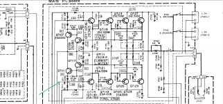
Another: the green arrow on the first capture is the pathway that connects with the image below involving that trimmer:
Attachments
Last edited:
Yes, I just modified the post above yours to contain an annotated portion of the schematic with the part #. It is now circled in green and the exit [or entry?] pathway is also in green. The green line goes off to [or comes from?] the first capture of the schematic in the current adjust and final stage. VR7101 and its twin VR7102.
The pathway appears to connect with a 2SA1360 device on the schematic in forum post #3, with a couple of other pathways connecting in beforehand.
Amp is a Duo Beta L435, whatever Luxman meant by Duo Beta.
Amp is a Duo Beta L435, whatever Luxman meant by Duo Beta.
Last edited:
Those adjustments are for idle current (bias). Check R7159 (output xsistor emitter resistor) for 5mv and adjust accordingly. Duo Beta is basically two different feedback paths. My Luxman CL34 has Duo Beta in the phono section.
Craig
Craig
These look to me like bias pots because that green line you put on there encompases the Vbe multiplier (ie bias circuit). Altering them will adjust the idle current through the outputs and personally I think there would be little to gain but a lot to lose if you fiddle too much with it!
Why are you bothering with DC offset adjustment? Unless you've got around 100mv or more on the outputs I don't think there is any point 'eff'ing with it. Nor would I know how to with this amp...
Why are you bothering with DC offset adjustment? Unless you've got around 100mv or more on the outputs I don't think there is any point 'eff'ing with it. Nor would I know how to with this amp...
Good news so far! I powered it up and the relay clicked nicely at the right time. No smoke! 😀😀😀
Sounds greaaaaaaaaaaaaaaat!!! [though I haven't checked the idle current bias yet]. The amp was working when I got it with slight weirdness in right channel that now appears to be GONE, weirdness that is. Temperatures are good. i can easily keep my fingers on the heat sink.
It really sounds nice......and if capacitors realy do need time to sound their best, all the better! I'm so happy😀 The Vifas are pleased...
R7159, thanks!
The pathway appears to connect with a 2SA1360 device on the schematic in forum post #3, with a couple of other pathways connecting in beforehand.
Amp is a Duo Beta L435, whatever Luxman meant by Duo Beta.
Those posts were the output bias adjust. Now you have to adjust it. BTW it was likely fine before you cleaned them.
G²
Thanks! I have left in the Nichicon KW 1.0uf 50V there. I was worried if it was part of an RC filter for a filter of critical nature like low pass or high pass.
So...All the electrolytics are changed, circuit board inspected and cleaned. I cleaned all the Alps PCB pots with contact cleaner and followed up with Deoxit Faberlube. They feel nice and smooth now.
Capacitors all from Digikey: Panasonic THA 105 degree 15000uf for main filter caps. Oddly, the Panasonics have a stated ESR the same as a Mundorf. 😎
2 of those for $25 and all the other capacitors, Elna Silmic II's and Panasonic FC's came to another $25 so not too bad of a hit, yet. A worhty investment so far, on top of the $50 to buy the amp in the first place.
Anyhow, before I fire it up I read through Saki's vintage amp tutorial and with regards to my Luxman L-435 there are two variable resistors, VR7101 AND VR7102.
Question for those more knowledgeable than me: Are these two variable resistors [1K volume controls on parts list of schematic] for adjusting output DC-offset between channels or are these variable resisitors trimmers for bias adjustment? I haven't touched 'em yet 😱😕🙄
If they are DC-Offset adjustment, I think Sakis mentioned to do it with no load. So........................let me run this by you: multimeter probes on speaker outputs? 200mv setting? Would the no-load [if even appropriate?] mean no resistor between speaker outputs? Or would I need a resistor across the speaker terminals to simulate a load? I think I read that somewhere too. So....confusione.
Attached portions of schematic relevant. If I have the flow right the variable resistor appears to head off to Final Stage. Which cofuses me because it appears in my mind that these trimmers could also be bias adjust for for whichever appropriate output devices? If so it seems that a multimeter could get ballpark on that adjustment?
The trimmers are circular and the tops have a white plastic outer cover on top with slots on top in a cross pattern. I'm worried they might be VERY sensitive [especially if not a multi-turn variety] and I don't want to eff with 'em without a reasonable forecast[ in advance yet] of possible outcomes:
It's part of a relay drive. The worst I expect is a little longer to 'wake up'. A mylar cap there would be fine but physically larger.
G²
Those posts were the output bias adjust. Now you have to adjust it. BTW it was likely fine before you cleaned them.
G²
NO, I left the VR pots uncleaned. What I cleaned with contact cleaner and faderlube were the front panel Alps pots. Ingrained FEAR kept me away from messing with the bias pots. So they are in the original position and condition.
Thanks for your added help, now that I read my original post I can see I didn't describe that properly.
It's part of a relay drive. The worst I expect is a little longer to 'wake up'. A mylar cap there would be fine but physically larger.
G²
The small 0.47u cap acts as a differentiator and generates a short pulse during relay shutdown. This pulse will reset the turn-on delay timer. It is not critical in value but should not be too low for proper operation.
Duo Beta is a dual feedback system indeed, but nothing different as a common DC servo circuit, actualy 😀
Hi! 40 watt,
I have the L435 luxman like you, I heard a noise in both channels and the sound isn´t good. The amplifier is 30 years old, what do you reccomend me? I´m thinking in change all the capacitors like you, Can you send me a list of all component and the complete Schematic of the L435?
Thank you a lot, sorry for my English
- Status
- Not open for further replies.
- Home
- Amplifiers
- Solid State
- Luxman L435 Capacitor Query