Hi.I want to build a discrete buffer with my components to drive my sennheiser hd25 and other headphones.And also want to use it before amplifiers.I do not want a preamp or opamp based circuit because they have feedback and it lowers bandwith..I had a look at internet but could find a good one.But i need a good schematic.I have these components
1) matched 2sk170/sj74
2) matched bc547c/557c - 546b 556b
3)bd 139/bd140
Maybe can use some other good components too
Any suggestions ?thank you very much
1) matched 2sk170/sj74
2) matched bc547c/557c - 546b 556b
3)bd 139/bd140
Maybe can use some other good components too
Any suggestions ?thank you very much
a NE5532 + bc546/556 + bd139/140 can make
an excellent class A phone amp, with good bandwith (500khz is enough?)
and signal noise ratio (100db) , very low distorsion (0.001%)....
an excellent class A phone amp, with good bandwith (500khz is enough?)
and signal noise ratio (100db) , very low distorsion (0.001%)....
Member
Joined 2009
Paid Member
I do not want a preamp or opamp based circuit because they have feedback and it lowers bandwith..
feedback usually increases bandwidth 😕
Something like this:
JEAN HIRAGA - Le Monstre Amplifier PCB
Though you should increase 1 ohms to 10 ohms
JEAN HIRAGA - Le Monstre Amplifier PCB
Though you should increase 1 ohms to 10 ohms
umut,
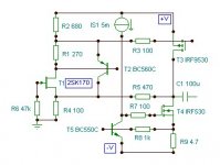
i pôst one that should work very well...
BD139/140 must be mounted on smal
heatsinks, they dissipate 1 W each...
R9 must be settled depending of you phone impedance,
you will have to tweak to find the best sound for
your taste..
quiescent current can be changed modding R6/R10 ,
be carefull not to exceed the output devices ratings..
hope that it will help, anyway, the circuit is very easy to
redesign according to your exact needs..
Attachments
Gareth,
It does not, in an absolute sense.feedback usually increases bandwidth
It does not, in an absolute sense.
More riddles. What do you mean precisely? Fb always seems to work for CRO traces.....
Hugh,
no riddles. In its function, global feedback uses excess gain that costs precious bandwidth. In practice, including any phase compensation, it means a much lower bandwidth.
no riddles. In its function, global feedback uses excess gain that costs precious bandwidth. In practice, including any phase compensation, it means a much lower bandwidth.
Hugh,
no riddles. In its function, global feedback uses excess gain that costs precious bandwidth. In practice, including any phase compensation, it means a much lower bandwidth.
Lumba you're the answer man.
Hugh,
no riddles. In its function, global feedback uses excess gain that costs precious bandwidth. In practice, including any phase compensation, it means a much lower bandwidth.
Please allow me to play "devil's advocate".
I do not understand why bandwidth would be considered "precious", in any audio circuit. The input, output, and power connections all need RF filters, anyway. And most well-designed circuits using modern semiconductor devices could have a bandwidth FAR in excess of what would be needed for audio, which can adversely affect the quality of the audio reproduction.
In fact, the bandwidth needs to be purposely limited, in all well-designed audio circuits. Without bandwidth limiting by RF low-pass filters, any RF that gets into the audio circuit will be rectified by every PN semiconductor junction that it encounters, which could change DC bias setpoints inside ICs, and in transistor circuits, for example, not to mention possibly introduce nasty demodulation products. The effects of those might not be insignificant, whereas the effect of lowering the overall bandwidth to a lower RF frequency will be less than insignificant, for any audio purpose. How much bandwidth do you think is needed, to not affect the audio quality?
At the same time, the benefits of a classical feedback control system approach, for improving the reproduction of audio, are extremely significant. There is no negative impact whatsoever from properly-applied negative feedback, in audio amplifier circuits, and especially not in a circuit with a killer audio opamp driving a power-booster amplifier (of any type) that is inside its feedback loop. The main impact of a feedback control loop, on an audio amplifier's performance, is much-lower distortion.
Very respectfully,
Tom
Last edited:
Something like this:
JEAN HIRAGA - Le Monstre Amplifier PCB
Though you should increase 1 ohms to 10 ohms
hi..Thank you very much.But i do not want feedback.I want to build unity gain buffer with a little high current.I think 100ma is enough
Wahab thank you too.but i want to build a buffer without integrated circuits.not opamps.only discrete components.
Member
Joined 2009
Paid Member
Sorry, we shouldn't be invading your thread with too much talk on feedback. It's one of those very interesting but contentious topics in audio which we sometimes can't resist talking about 🙂
The circuit Le Monstre has a very good reputation for it's nice sound and could be a good option for you.
I also like the circuit that Lumba posted, it looks quite interesting. The JFET input giving high input impedance and also JFETs have a good input dynamic range if I understand these things properly. The BJT provides current buffer to the input JFET. Looks very nice with fewer parts than LeMonstre.
Member
Joined 2009
Paid Member
some other links that may be of interest to you:
HeadWize Library - Projects
http://www.diyaudio.com/forums/aksa/152031-aspen-headphone-amp.html
http://www.diyaudio.com/forums/soli...llower-diamond-buffer-power-output-stage.html
HeadWize Library - Projects
http://www.diyaudio.com/forums/aksa/152031-aspen-headphone-amp.html
http://www.diyaudio.com/forums/soli...llower-diamond-buffer-power-output-stage.html
Member
Joined 2009
Paid Member
scott,
in this trade we don`t get something for nothing.
you mean there is another trade where we can ? 😛
- Status
- Not open for further replies.
- Home
- Amplifiers
- Solid State
- high current discrete audio buffer