Hi Tomat
Selamat pagi.
(here is the morning)
I had a look on your drivers transistors datasheet.
MJE3055 are 60 Volts devices.
They cannot suit here. You need 120V min.( full swing)
Do you still use them? or did you change?
The pre drivers are overkill too.
Selamat pagi.
(here is the morning)
I had a look on your drivers transistors datasheet.
MJE3055 are 60 Volts devices.
They cannot suit here. You need 120V min.( full swing)
Do you still use them? or did you change?
The pre drivers are overkill too.
Hi Tomat
Selamat pagi.
(here is the morning)
I had a look on your drivers transistors datasheet.
MJE3055 are 60 Volts devices.
They cannot suit here. You need 120V min.( full swing)
Do you still use them? or did you change?
The pre drivers are overkill too.
Hi Bobo🙂
selamat malam (here is at night now)😀,.. i'm very surprised that you able to speak Indonesian,but please don't ask me for speak french😀.
no,i'm not using them again,now i'm using 2N6491 and 2N6488,they only could reach 80v,but this time i only these,i will looking for others later.
the unstable bias on my amp that cause BD139/140 vbe mult,maybe i got the fake,today i replace them with 2N6491/6488 also,they look more-more stable 🙂,and also they sound much better than BD's
Bobo.. i plan to use mills resistors at emmiter output device (0.47R resistors),is it will give significant effect? what do you think?
thanks very much
I do not recommand that you use too low voltage transistors.
You risk to blow up the whole buffer.
The middle point can swing from one rail to the other.
If your rails are 55 volts then you absolutely need 110volts min devices.
Wirewound resistors have been in use there for decades. I do not know how much is the difference.
...spent two month in Bali, Lombok and Sumbawa besar some years ago.
I went to Malaysia too.
I just know a few words.
Terima kassi.
Last edited:
I do not recommand that you use too low voltage transistors.
You risk to blow up the whole buffer.
The middle point can swing from one rail to the other.
If your rails are 55 volts then you absolutely need 110volts min devices.
Wirewound resistors have been in use there for decades. I do not know how much is the difference.
...spent two month in Bali, Lombok and Sumbawa besar some years ago.
I went to Malaysia too.
I just know a few words.
Terima kassi.
Selamat pagi 🙂
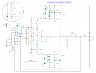
apa kabar? (means "how are you")🙂, i have try in ltspice for reducing value of C3 until 0.01uf,it's looks give better frequency response,but i'm not trying on my amp yet,how do you think about this?
thank you
Attachments
Kabar baik.
i think C1 value is not significant. But Cx and Cy count for high frequency response.
I have built the second channel.
2 x 5 pairs / channel now.
63 volts rails.
35 mA bias / device seems stable.
i think C1 value is not significant. But Cx and Cy count for high frequency response.
I have built the second channel.
2 x 5 pairs / channel now.
63 volts rails.
35 mA bias / device seems stable.
I have only one Vbe mult in the middle of the current sources.
I enter symetrically into the output stage.
It certainly could be used also in a symetrical way. SC5171 /SA1930.
I must say the current sources and the first EF stage are integrated into the chip.
But the principle is indentical.
I do not know why you have such high value resistors in your Vbe.
Input impedance?
Anyway, i am quite shure you can make things better fitting this Vbe on the heatsink. That is compulsary to track temperature.
Then you need to set bias when warm.
If you get distortion when cold, then the Vbe is not correct.
This isn't a royal way and especially by a power follower BjT triple a bad way. Please note, there are at each half three base-emitter junctions in the temperature independent loop.
The first schematic version (two VBE multiplier in antiserial) is already better, because each power transistor gets his own sense transistor, that I can mount nearly by the power transistor. Please read articles about this URLs carefully:
http://www.hagtech.com/pdf/vbe.pdf
Madrigal Library: Adaptive Bias
http://www.diyaudio.com/forums/solid-state/29957-sziklai-pair-vbe-multiplier-2.html
Electronic Design Welcome
http://www.diyaudio.com/forums/parts/21577-sanken-lexam-sapm01-audio-transistors.html
http://www.ece.drexel.edu/courses/ECE-E352/ClassABAmp.pdf
Vbe multiplier
Vbe Multiplier
Patent US4160216
Last edited:
This bad way is the National lme49810 application note.
It works nice for me.
LME49810 - 200V Audio Power Amplifier Driver with Baker Clamp.
Thanx for the links ( i already knew some of them)
It works nice for me.
LME49810 - 200V Audio Power Amplifier Driver with Baker Clamp.
Thanx for the links ( i already knew some of them)
Kabar baik.
i think C1 value is not significant. But Cx and Cy count for high frequency response.
I have built the second channel.
2 x 5 pairs / channel now.
63 volts rails.
35 mA bias / device seems stable.
yeah🙂,you're right bobo,Cx and Cy are dominant aspect on high frequency,few days ago,i'm using poliprophylene caps for Cx an Cy,they give bad result,and the i replace them with silver mica,i feel they are better for that application
I think Cx and Cy aren't not needed. See original schematic.
The internal capacitances of the many outputs transistors are enough.
The internal capacitances of the many outputs transistors are enough.
nice and useful articles Tief🙂
Hallo tomat,
today I discover the right name of your circuit: it is the "T-Circuit"
The exactly title name of the according article about the "T-Circuit" is follow:
"An Ultra-Low Distortion Direct-Current Amplifier" from the author
BART N. LOCANTHI (James B. Lansing Sound, Inc.
http://www.harman.com/EN-US/OurComp...ip/Documents/Scientific Publications/1091.pdf
By another thread Mr. Bob Cordell mentioned this one and therefore I have found this article
Hello Tief 🙂
sorry for this late reply, it's interesting circuit, Tief ,i was sent you pm,would you please to check?
thanks
Hi Tomat,
i found this, which is close to your buffer.
Andrea Ciuffoli - Home Page
http://www.audiodesignguide.com/my/Cool_Follower2.GIF
i found this, which is close to your buffer.
Andrea Ciuffoli - Home Page
http://www.audiodesignguide.com/my/Cool_Follower2.GIF
I discover only the PS. Mean you this follower?Hi Tomat,
i found this, which is close to your buffer.
Andrea Ciuffoli - Home Page
http://www.audiodesignguide.com/my/Cool_Follower2.GIF
http://www.audiodesignguide.com/my/Cool_Follower1.GIF
More exactly this one
http://www.audiodesignguide.com/my/Hot_Follower2.GIF
Though i realise now it is different. That is a diamond buffer working in class A, close to ES200, at final.
Is there any advantage to use a floating ground?
http://www.audiodesignguide.com/my/Hot_Follower2.GIF
Though i realise now it is different. That is a diamond buffer working in class A, close to ES200, at final.
Is there any advantage to use a floating ground?
Last edited:
Today I have only just discovered the area for the private messages (PM - I do not know this abbreviation until now) in diyaudio - it's full of messages from many members.Hello Tief 🙂
sorry for this late reply, it's interesting circuit, Tief ,i was sent you pm,would you please to check?
thanks
Better it is in generall, sending PM's to my own e-mail address (go to public profile - therefore click on my member name at left site of my diyaudio-post).
By the way - the member name "Tiefbassuebertr" is based on my weblink "www_tiefbassuebertragung_de"
To your problem:
Without much experience with circuit traces, I strongly advise you to build the power follower only two stages (or one single ended power follower stage with MOSFET). By many finished amplifiers, that have three or four stages like yours, I reduce to two stages (i. e. normal darlington configuration) very often. Only in this way I eliminate wild oscillations sometimes in the MHz aera.
The URLs of the previous post is a good solution for you.
Last edited:
I would like to transpose the Nelson Pass F5 design, cascoding the input Jfets, and degenerating smaller power output mosfets.
But for starting with the buffer i will use an existing voltage amplifier.
I want to listen to the buffer first.
If you like to use Firstwatt, it has enough current already and need only single stage emitter follower.
Hi Tomat,
i found this, which is close to your buffer.
Andrea Ciuffoli - Home Page
http://www.audiodesignguide.com/my/Cool_Follower2.GIF
Is your buffer not finished yet?
My cheap is finished, all components replaced with cheaper again and again, and the sound is nothing special, but gets worse and worse through "cheaping". The last test, it is normal in morning and blow at noon caused by limited heatsink, too hot at rated power. If we double the mosfet for class AH branch, then it become expensive, out of cost. Then this project stopped and we focus in other project.
Attachments
Helloo All 🙂🙂🙂
sorry for my verryy late reply 😀,
Bobo: thank you for the nice info,i will try it
tiefbassuebertr: thank you,all my amp problem are solved 🙂,yes,i was sent you pm's,later i will contact you through your web 🙂
sorry for my verryy late reply 😀,
Bobo: thank you for the nice info,i will try it
tiefbassuebertr: thank you,all my amp problem are solved 🙂,yes,i was sent you pm's,later i will contact you through your web 🙂
Is your buffer not finished yet?
My cheap is finished, all components replaced with cheaper again and again, and the sound is nothing special, but gets worse and worse through "cheaping". The last test, it is normal in morning and blow at noon caused by limited heatsink, too hot at rated power. If we double the mosfet for class AH branch, then it become expensive, out of cost. Then this project stopped and we focus in other project.
Sorry for this late answer.
Finally i used the triple EF as an output stage driven by an lme49810 @63V rails and stopped there for now.
I actually use it for my subs.
I am just finishing an aleph J and i am planning to mod it as an SRPP output. Though i need to listen to it as a stock aleph J first.
What is your new project?
- Status
- Not open for further replies.
- Home
- Amplifiers
- Solid State
- Help with this amp