By increasing the feedback resistors. Less feedback = more gain. And a bit more distortion.
Last edited:
By increasing the feedback resistors. Less feedback = more gain. And a bit more distortion.
Thank you!
Is there a formula for this so that I could get the exact gain I want?
Last edited:
A formula that predicts with great accuracy would not
be practical, as it depends on the character of individual
gain devices and temperature and such.
Perhaps you should just use a trim pot on the feedback
resistors.
😎
be practical, as it depends on the character of individual
gain devices and temperature and such.
Perhaps you should just use a trim pot on the feedback
resistors.
😎
A formula that predicts with great accuracy would not
be practical, as it depends on the character of individual
gain devices and temperature and such.
Perhaps you should just use a trim pot on the feedback
resistors.
😎
Wow, very honored. I will probably just buy a few more resistors to get a somewhat higher gain (It doesn't have to be exact. I thought that a formula can give me a range of values).
I just found this on page 505:
Don't forget to change R1&R2 as well
R5&R6 = 50ohm, R1&R2=10ohm
R5&R6 = 100ohm, R1&R2 = 22ohm
R5&R6 = 150ohm, R1&R2 = 30-35ohm
etc
(leaving out R7&R8)
For a gain in the range of 8-12x, what would be the rough range of values for R5&R6 (leaving out R7&R8) and R1&R2? Thanks!
Teabag sent me some Mills 0.47 Ohm -- I set the reference resistor to 0.500 Ohm Caddock:
bigger image here:
http://www.tech-diy.com/Components_Passive/Half_Ohm_Mills.gif
And Trial 2 of the Caddock's with the new reference resistor:
bigger:
http://www.tech-diy.com/Components_Passive/Half_Ohm_Caddock2.gif
An externally hosted image should be here but it was not working when we last tested it.
bigger image here:
http://www.tech-diy.com/Components_Passive/Half_Ohm_Mills.gif
And Trial 2 of the Caddock's with the new reference resistor:
An externally hosted image should be here but it was not working when we last tested it.
bigger:
http://www.tech-diy.com/Components_Passive/Half_Ohm_Caddock2.gif
Jack,
Looks like it's still not as tight as the Caddock, but is a little better than a panasonic.
Of course, I really dont know what this all means, in mathematical relationship terms, does the test show us the Caddocks generally track better, run at a certain, impendence, frequency and temp?
It begs the question - are the Caddocks worth the price?
A formula that predicts with great accuracy would not
be practical, as it depends on the character of individual
gain devices and temperature and such.
Perhaps you should just use a trim pot on the feedback
resistors.
😎
Hi Mr. Pass,
How about 100ohm with 200ohm trim? And the trim pot would need to be 2W or so?
Hi all.
Can I use Aleph supply to feed F5?
Isn't that voltage (34V DC) too high for F5?
Any risks beside higher bill for electricity ? 😀
Can I use Aleph supply to feed F5?
Isn't that voltage (34V DC) too high for F5?
Any risks beside higher bill for electricity ? 😀
Last edited:
Jack,
Looks like it's still not as tight as the Caddock, but is a little better than a panasonic.
Of course, I really dont know what this all means, in mathematical relationship terms, does the test show us the Caddocks generally track better, run at a certain, impendence, frequency and temp?
It begs the question - are the Caddocks worth the price?
After 2 "see-throughs" you won't notice the difference.
The jig adds about 10 milliohms to the impedance.
The macro can be downloaded from AP's website -- it's one of those VBA's so you'll have to download the 2700 software first and run in demo mode. It's not like VB where you can "deploy" a project.
I took out my capacitor bank -- which was some computer grade Mallory's -- replaced with the Zen like CRC supply (30,000uF 4x 0.47R, 30,000uF), moved the transformer onto the front panel -- the noise is a trifling 43uV 22Hz -- 22kHz, 9uV "A" Wtd.
... now try some Epcos B41560s (33,000uF) or if the budget can stand it, some B41550 41570) Sikorels - a step up again.
I do use some bipass Sikorels (Audionote, California - eBay), but usually end up having to add some snubbers as many bipass efforts tend to create extra osc, etc. can be a real PIA!
Really appreciate your site - good to know your facilities, products, kits, matching available, and esp at the prices - many thanks.
Almost, but not quite up to the results which were published in AX -- the analyzer is running flat out (to 500kHz) so it picks up a bit more environmental noise -- dotted lines are 10W and 20W.
An externally hosted image should be here but it was not working when we last tested it.
Hello JackinnJ,
are you able to show square and Sinewave (20hz/1K/20K ) outputs @ 20 Watt
regards,
are you able to show square and Sinewave (20hz/1K/20K ) outputs @ 20 Watt
regards,
I do use some bipass Sikorels (Audionote, California - eBay), but usually end up having to add some snubbers as many bipass efforts tend to create extra osc, etc. can be a real PIA!
Hi jameshillj,
How close were the bypass caps to the PCB? I recall NP saying they should be 6" or more away to prevent oscillations.
5w is lower than 1 watt??
_-_-bear
5W is red. I think I got it right. Aaats raight as Liza Doolitle was wont to exclaim to Prof. Higgins!
This is a bit of a compromised F5 -- there are caps to limit RFI on the JFETs inputs and I matched the input gatestoppers to their input capacitance, I found it helpful to put some joules on board in the form of Elna Silks.
This is one great sounding amplifier. It's the Occam's Razor of Amplifiers!
Hi Alzira,
Yeah, I wondered about that too, as I like to bring the power supply as electrically close to the "work place" as possible but anyway, I looped 'em up a bit to have about 8" leads (double 1mm 4-9s Si wire) and no problems.
I was rather curious just how far I could effect the amps performance/sound by going a bit over the top with this bipass and snubber "stuff" - I think it's a bit different again when the amps go into AB mode, something about changing the balance of the harmonics and the bipass caps characteristics effect the sound more, for better or worse. [IMO, that is!]
I have Cmultipliers on the rails now (extra volts on trannie) and surprisingly, changes to the diodes/supply caps still directly effect the sound of the amp.
Rather interesting, these "simple" amps!
Hello,
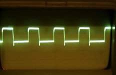
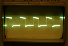
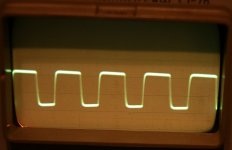
Here I attached a photo of my F5 square wave picture @ 20kHz (approx.10R dumb load) and the original square wave @20kHz directly from generator to scope. Also for compare here is Leach amp square wave picture@ 20kHz. What causes these peaks F5 picture?
Is it a generator failure which is old maybe? Or, f5 does not work as is necessary>? Sound of my F5 is great IMHO.
Thanks in advice.
Attachments
- Home
- Amplifiers
- Pass Labs
- F5 power amplifier