Hello all
I have been working on this project for some time now, and just getting towards the end of the tunnel
I designed the boxes to maximize a 1200mm sheet of mdf with little wastage in cutting etc I think that the term used in cd process is nesting
At present I have contracted a woodworking company to cut out the panels using a cnc machine, the first boxes will be proto out of 18mm sheets that they use to protect the veneered stuff, my cabinet maker suggested this as it is basically free comes with the good panels! When all the tweaking has been finalized we will use 25 mm veneered mdf for the final product.
I requested that the driver relief’s be rounded on the rear of the baffle to aid in air movement from exhaust of the cone, hope that this is the correct practice
I have included a hand drafted design for your perusal; the top section is in its own enclosure I haven’t drawn in any bracing but intend to rout out another dividing panel mid way in both upper and lower chambers, these will get the useaual relieving so not the take up to much volume
The mtm section was placed off centre in an attempt to cancel diffractional sound it may give an unappealing appearance but I hope that it is functional
Driver centre line placement is 145 mm this is the wave length for my desired crossover frequency which will be 2380 Hz
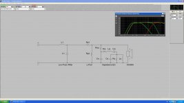
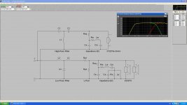
The mains are a bit of a worry for me at present as the cone excursion seems excessive for the load, peerless indicate that they will handle 150 watts which is the criteria that I used in bass box also the crossover is another area of concern, I used third order two way for the mtm and have tried to use separate second order for the bass driver, this is going to present some problems with impedance
If any of you have any advise in this area I would be more than grateful
The snap shoot of the bass xo is an overlay of the mtm section I was hoping that this May workout but am unsure at present
I will provide enough terminals on the rear of the cabinet to bi wire and or bi amp, I know that bi amping will ease the cross over worries but would like to keep the equipment list down
I hope that I get some sound advice (no pun intended)
Cheers speedie
I have been working on this project for some time now, and just getting towards the end of the tunnel
I designed the boxes to maximize a 1200mm sheet of mdf with little wastage in cutting etc I think that the term used in cd process is nesting
At present I have contracted a woodworking company to cut out the panels using a cnc machine, the first boxes will be proto out of 18mm sheets that they use to protect the veneered stuff, my cabinet maker suggested this as it is basically free comes with the good panels! When all the tweaking has been finalized we will use 25 mm veneered mdf for the final product.
I requested that the driver relief’s be rounded on the rear of the baffle to aid in air movement from exhaust of the cone, hope that this is the correct practice
I have included a hand drafted design for your perusal; the top section is in its own enclosure I haven’t drawn in any bracing but intend to rout out another dividing panel mid way in both upper and lower chambers, these will get the useaual relieving so not the take up to much volume
The mtm section was placed off centre in an attempt to cancel diffractional sound it may give an unappealing appearance but I hope that it is functional
Driver centre line placement is 145 mm this is the wave length for my desired crossover frequency which will be 2380 Hz
The mains are a bit of a worry for me at present as the cone excursion seems excessive for the load, peerless indicate that they will handle 150 watts which is the criteria that I used in bass box also the crossover is another area of concern, I used third order two way for the mtm and have tried to use separate second order for the bass driver, this is going to present some problems with impedance
If any of you have any advise in this area I would be more than grateful
The snap shoot of the bass xo is an overlay of the mtm section I was hoping that this May workout but am unsure at present
I will provide enough terminals on the rear of the cabinet to bi wire and or bi amp, I know that bi amping will ease the cross over worries but would like to keep the equipment list down
I hope that I get some sound advice (no pun intended)
Cheers speedie
Attachments


Hi Speedie, with regards to the power handling, I think you will find that manufacturers power rating specs, are just the max poewer the driver will handle without burning out. You may find that the max power that they can handle before exceeding Xmax is MUCH lower.
Remember that Xmax is simply the maximum <b>linear</b> excursion of the driver, depending on the driver in question the behaviour when exceeding this may be ok or may be terrible.
150W is a lot of power! Unless you are planning on using them as party speakers under normal circumstances they will be having to deal with a lot less than that! 🙂
I seem to remember asking a very similar question about 6 years ago 😉
Tony.
Also on the centre line (and driver offset) have you modeled it in BDS (baffle diffraction simulator)
I originally was going to do the same, but found that I got the biggest (simulated) improvement with a 45 degree chamfer, which could not be achieved if the drivers were off centre due to my narrow cabinets.
It is rather scary, I was modelling this speaker back in 2003, and It still isn't done yet, but I guess in my defence there was aprox four years where I did absolutely nothing on it 🙂
Tony.
diffraction
Thanks for your response Tony
With regards to the driver alignment in the upper section I have read Ray Alden’s book on speaker design and theory which he states that if you use this formula (3.5squareroot of2) it gives an irrational ratio between the distances to the edges of the box
I checked out the site that you linked for diffract ional formula but it indicates that it is for sealed boxes (ports?)
I am using bass box as a guide program because it was given a good write up in the book.
Like all things it takes some time to understand how things work I downloaded a trail version of leap xo and enclosure software and I can see the advantage of this program as It looks like an industry standard, but again it would be like trying to self teach Japanese
My main concern is the crossover section for the bass section of the project
You say that you where workings on a similar concept back in 2003 do you have any of your calculations from that time. (Should be finished now 2003+4=2007)
Time flies when we are having fun
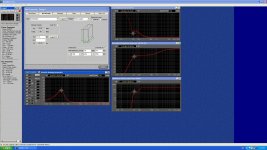
I don’t want to over drive the speakers but if you look at the excursion graph of both sections you can see that @150 watts for the top (mtm) it is fine but the bass (lower) is going to exceed its limits
I know that at just one watt input you can get some descent db
Cheers Speedie
Thanks for your response Tony
With regards to the driver alignment in the upper section I have read Ray Alden’s book on speaker design and theory which he states that if you use this formula (3.5squareroot of2) it gives an irrational ratio between the distances to the edges of the box
I checked out the site that you linked for diffract ional formula but it indicates that it is for sealed boxes (ports?)
I am using bass box as a guide program because it was given a good write up in the book.
Like all things it takes some time to understand how things work I downloaded a trail version of leap xo and enclosure software and I can see the advantage of this program as It looks like an industry standard, but again it would be like trying to self teach Japanese
My main concern is the crossover section for the bass section of the project
You say that you where workings on a similar concept back in 2003 do you have any of your calculations from that time. (Should be finished now 2003+4=2007)
Time flies when we are having fun
I don’t want to over drive the speakers but if you look at the excursion graph of both sections you can see that @150 watts for the top (mtm) it is fine but the bass (lower) is going to exceed its limits
I know that at just one watt input you can get some descent db
Cheers Speedie
Hi Speedie, unfortunately I have not finished the project... 2003 I was just theorising, I don't think I bought the drivers until Dec 2004 ... then I made a dodgy test box as I didn't have the right tools to do it myself (I like your idea of getting a cnc shop to do your pannels)! so In Aug 2005 I spent a couple of weeks at my parents place and made some boxes. Then I got an ultimatum I was spending too much time on speakers and not enough time looking for a new job, and the project got shelved... Just started again recently at the point I left off in Sep 2005.
Anyway, I'm pretty sure from memory that BDS only takes the baffle dimentions as parameters, it doesn't model the enclosure (maybe it uses a simple closed box rolloff assumption in the graph) but the lower frequencies are not really that important, it is more important for the higher frequencies which your mid cabinet will be operating at.
I did do lots of calculations and some of them may have been posted in various threads here, but I couldn't put my hands on them easily. One thing I know I was considering doing was making the crossover freq for the woofer cabinet correspond to the baffle step freq based on the baffle width, which for what I was planning was around the 300Hz mark... I'm doing totally separate cabinets for the woofers and there may be some issues in that the woofer cabinet is wider than the mtm, but I'll deal with that when the time comes 🙂 I'm hoping the amount of BSC I need is nill on the woofers (just vary the gain on the woofers amp) and minimal on the MTM's. I hope I wrote it down somehwere, but knowing me, I probably didn't and used my various threads as my notes...
OK I found the closest thing to notes that I can This Thread 🙂 Interestingly I'm talking about 200Hz here not 300 which is what I remembered, might be a good thing you asked me the question! 😉
Tony.
mid driver alignment thoughts
Well I still haven’t gotten my boxes from the cnc dude seems like time fly’s by
Would anyone like to comment on the offset idea that I propose I have used this to help with diffractional loses but as far as aesthetics go it does look well not symmetrical
Would it be a reasonable idea to say leave the tweeter where it is and then bring the two mids back onto the centre axis?
This would maybe defeat the geometry of the mtm concept
Any comments greatly appreciated
Cheers speedie
Hi Speedie, I was browsing over some of my older posts, and apparently one of the reasons I decided not to offset my drivers was some info that Duntech had on their website. TECHNOLOGY go down to minimising difraction distortion.
Tony.
Tony.
unfortunately Ray Alden's book, while being a very good beginners guide, doesn't cover quite a few issues. Baffle step loss is one of them. Non linear distortion is the other big issue.
Because individual phase of the drivers will be affected by the crossover, it will change over all Frequency response of a loudspeaker and you may end up with big deeps or humps. Crossover Pro doesn't really account (and can't) for a phase of the drivers used.
Because individual phase of the drivers will be affected by the crossover, it will change over all Frequency response of a loudspeaker and you may end up with big deeps or humps. Crossover Pro doesn't really account (and can't) for a phase of the drivers used.
Hi, Wintermute,
Do you remember me? We had a few e-chats a few years ago. How are you? Welcome back!
Speedie,
Roundover can reduce baffle reflection. My speakers have roundovers of 70mm radius and measurements show (on and off axis) very smooth response comparing to hard edges.
Also, offset from centre for driver location would only make the frequency response appear to be better at the centre point, it does not improve the overall (off axis) smoothness of the frequency response, and introduces asymetrical frequency response to the left and right sides of the speakers.
Regards,
Bill
speedie
On the opening at the rear of the driver you are better off with a 45° chamfer than a radius (see Troel's site for some examples).
I think it was John K that said offset drivers can cause more issues than it corrects unless it is spot on.
Cone excursion in these models tends to not line up with music signals in the real world. Sure, take note and try and reduce but don't lose too much sleep over it. Besides.... 150W is very LOUD. 😱
I don't know if you have the drivers but do consider the Peerless 810921 instead of the XT25TG as it is heaps better IMO.
Watch the rise between 1K-3K as can be too much on the ears but of course can be tweaked to suit.
I can't follow the need for an L-pad in the woofer and I think it's going to struggle to keep up with dual 830875 in an MTM but I notice you have that padded as well. The woofer in reality needs to help with BSC. There is a possibility it may need 2 per side to keep up (I haven't modelled it so only a hunch).
The crossover does seem over complex for the Nomex drivers as I've had a lot of experience with them. They tend to work well without the need for very high order crossovers and corrections.
Your design is heading in a good direction but keep motoring on as more effort in design pays off in cost and time savings. You might get some ideas from the Elsinore design that uses the 830875 to good effect..... very clever design.
Last edited:
Hi, Wintermute,
Do you remember me? We had a few e-chats a few years ago. How are you? Welcome back!
Regards,
Bill
Thanks Bill, yes I do, I never did get over with my measurement stuff did I. I'll send you a PM so this thread doesn't go off topic!
Tony.
- Status
- Not open for further replies.
- Home
- Loudspeakers
- Multi-Way
- suggestions with mtm mains