So, Anyone with a good and simple idea for a final stage amp in the category of 200-300wats per channel out there?
I see you are a new member. Welcome to the forums. You should post such a question to the solid state power amplifiers section.
Hi Salas and everyone!
After the 2 test circuit *Simplistic Mosfet HV Shunt Regs and ''Simpler Simplistic''*
I saw ''Simpler Simplistic'' circuit design is simple and very good, high stability, very low noise. I enjoyed it, therefore I make PCB 5 for members that volunteer work and try board of ''Simpler Simplistic''.
I will send five members register first! So who are brave and like the registration???,
Thanks!
Simpler Simplistic
Salas, must some resistor values be changed for the existing schematic if input voltage is lowered to 260V? I'm aiming for 35mA total current draw, 8mA to the load.
Salas, must some resistor values be changed for the existing schematic if input voltage is lowered to 260V? I'm aiming for 35mA total current draw, 8mA to the load.
Ah, I went back too far: [URL="http://www.diyaudio.com/forums/attachments/power-supplies/146954d1258380808-simplistic-mosfet-hv-shunt-regs-ssregjfet.gif]schematic[/url] and [URL="http://www.diyaudio.com/forums/power-supplies/134801-simplistic-mosfet-hv-shunt-regs-68.html#post1974134]explication[/url].
Having good stock of J202, these can be used instead of 2SK170 you mentioned. From the days of long hair and wild experiments I kept some LR8U which were in my own lousy regulators. Any use for these cheap thingies? SMD though. Coming to think of it, haven't smoked a single semi this year. Life is getting boring overhere
Edit: just remembered I had to flip the mains fuse last week, in the dark. A stupid indicator bulb had '220' on it -it seemed so at that time (evidence has vaporised)- and went out in a joyfull boom. No harm done unfortunately
Last edited:
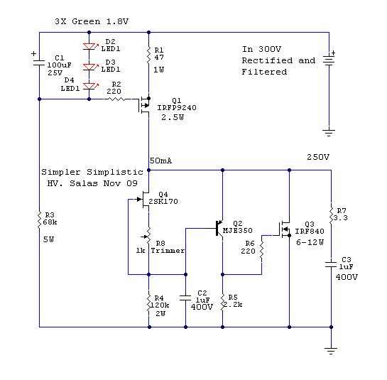
I don't know why, I can't get the links to work in my browser. So I prepared a simpler simplistic schematic for 260V in, 210V out, with under 40mA ccs for you. Has MPSA-92 that you already have, as well. I don't have a J202 model in my libs right now. Because the 2SK170BL of the schematic has much more Idss, you must select off circuit a J202 that with some trial resistor connecting G,S will measure 1.74mA under 1V Vds. Then you can put them in the circuit using that J202 & test resistor or a trimmer around its value where the 2SK and the 500R trimmer are in the schematic.
Attachments
What typo? Ah, the 300V in? I forgot to write, bcs its text. I simulated with 260. Will upload new, thanks.
I'm not being picky...😱
schematic says 300V in so it's really minor, of course all parts values are good.
schematic says 300V in so it's really minor, of course all parts values are good.
Disco is an oldyes, Disco's links are not working for me either...
 schematic and explication.
Sorry about that 🙄
I'm not being picky...😱
schematic says 300V in so it's really minor, of course all parts values are good.
I changed it. Its nice you spotted. I used a 300V previous one and changed the battery value but forgot to write the text again. It can work with 90V dif BTW, heat will not be that much for just 37mA CCS Mosftet, if the transformer happens to come from a higher B+ project.
You got your custom schematic meanwhile, so ready you are. J202 has low Vt-, its OK for that. Only find the right Idss and g,s resistor value as I mentioned.
Salas, must some resistor values be changed for the existing schematic if input voltage is lowered to 260V? I'm aiming for 35mA total current draw, 8mA to the load.
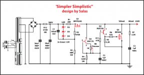
Hi! You can se, i use new design of Salas for my pre!
Attachments
But you have changed R6,C3 to your liking again.🙂 Plus your 9240 symbol orientation is wrong.
Ok! thank Salas
Attachments
Hello Salas
what about changing the input filter from CRC to LC, for example 10H and 47uF? As well using a tube rectifier instead of the solid state bridge rectifier.
Regards
Joao
what about changing the input filter from CRC to LC, for example 10H and 47uF? As well using a tube rectifier instead of the solid state bridge rectifier.
Regards
Joao
post796.
at start up and if the output is shorted the 9240 sees 300V for a 200V device.
Is this a problem?
at start up and if the output is shorted the 9240 sees 300V for a 200V device.
Is this a problem?
Hello Salas
what about changing the input filter from CRC to LC, for example 10H and 47uF? As well using a tube rectifier instead of the solid state bridge rectifier.
Regards
Joao
We do it all the time.😉 The very first one had a choke for instance, others use a tube rectifier aswell. Its just one member's shunt build that one above.
- Home
- Amplifiers
- Power Supplies
- Simplistic mosFET HV Shunt Regs