Hello,
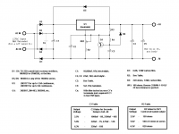
I found these DC modules that retail for about $200USD a pair. I was looking at the simplified schematic they provided on the website and was wondering a few things about them.
Will you take a look at these for me and tell me if I can achieve the same thing with a self made module using a 78xx voltage regulator.
Here: Tube filament supply
As an experiment I was going to use the same thing I hand built from scratch for the KT88SE project I just finished, a simple rectifier bridge followed by a cap and voltage regulator and then another cap. Of course I provided DC to an indirectly heated filament tube (KT88) and I understand the DHT is entirely different.
This production module appears to have a few more IC's as a current source and something else. They are very expensive, about $200 a pair. I wanted to make my own modules that simply converted the AC to DC. Can one still install a hum pot with a DC source to the filaments if I chose to make a simple rectifier/filter module of my own? What is the purpose of the other stuff in their circuit and is it truly needed?
Best would be if somebody knew of a schematic that would provide me with the same results as these modules that I could just build myself for less $$$.
Thanks for your help.
Jeff
tell me if I can achieve the same thing with a self made module using a 78xx voltage regulator.
With idhts i am quite happy using a 317 as a constant current source. Raw dc quality is still audible but it will probably remain so even with a high performance ccs. $200 for a ccs with automatic voltage control seems a bit silly.
With idhts i am quite happy using a 317 as a constant current source....
I am not sure we are on the same page. I am planing to use the LM317 as a voltage regulator and smoother for the filament supply on a DHT, not the cathode current supply (which I have done elsewhere). Usually on a DHT the filament is supplied with an AC current/voltage with a hum pot. I want the filament to be heated with DC instead of AC.....so are we on the same page???
Jeff
Assuming your DC supply can handle being floated at the cathode voltage you're running, I don't see any issue with running a regulated DC supply for DHT heaters. That's been done before.
The humdinger pot should not cause trouble when you convert to DC. It probably won't do much, but I don't think it'll cause trouble either.
With DC heaters, you have two options: Constant current or constant voltage. Both can be accomplished by an LM317. See Morgan Jones, "Valve Amplifiers" for more info.
~Tom
Ok, another question...the amp I am in the process of building the Hagtech Clarion 2A3
here: CLARION 2A3 Stereo SET Amp (follow link to article on that page)
He is using 2 separate filament supplies for a balanced cathode drive and no hum pots. Is this better than a filtered DC supply on the filaments....am I gaining or losing anything by rectifying the filament heater supply?
It just seems to me that a good filtered very low ripple heater supply would be better than anything AC, even this balanced cathode drive.....but I never fail to be suprised by what I learn. BTW this is my first DHT amp to build and I just want it to be one of the best I have built too.
Jeff
Hi,
I'm in the process of making dedicated soft-start filament supplies and have boards on hand.
They use LM317T for up to 1.5A continuous and LM338T for 5A continuous.
I have a few blank PCB's ready and a lot more about three weeks mail away.
Cheers!
**edit**
Added PCB schematic
I'm in the process of making dedicated soft-start filament supplies and have boards on hand.
They use LM317T for up to 1.5A continuous and LM338T for 5A continuous.
I have a few blank PCB's ready and a lot more about three weeks mail away.
Cheers!
**edit**
Added PCB schematic
Attachments
Last edited:
Their module is specifically for DHT.
Their module is floating supply input and then they *ground* the 'positive' output to the audio ground end of the filament. Hence their module's 'negative' output is towards the more positive end of the filament. Look at the diagram and notes on page 6 of their application note:
http://www.tentlabs.com/Products/Tu...Filament_supply_Application_Note_V01_AN02.pdf
I do not know why they do that but the designer is intelligent so there must be a reason. In other words it is significant, and it is best be understand it before you can hope to DIY copy it.
Anyone know why it is connected that way?
I know you Brits are 1 hour ahead of us so you must have still been very drowsy posting that 😱
What's good for the goose ...
I just did. What you said makes absolutely no sense 😀 If "-" terminal is at lower potential vis a vis "+" terminal and "+" terminal is attacked to amplifier's ground, the other end of the filament will be more negative. This is just how electricity works. It's cannot be "more positive".
Is he ? He forgot (or neglected to) balance heater supply in relation to ground. He's charging $200 for a board that is worth no more than $50 in components and time if custom made in miniscule quantities so he's definitely cunning businessman. This proves the old adage that there is a new sucker born every minute ... and it'd be a shame to let them keep their money.
Because that's the way he drew his picture. It doesn't matter which way you turn the leads as long as you keep the same voltage differential from both ends of cathode to the rest of the tube (by tying negative lead to the ground he would have lost Vf volts).
Mmm, I think I should get into business of selling regulator boards at 5 times their actual value ...
Their module is specifically for DHT.
What's good for the goose ...
Their module is floating supply input and then they *ground* the 'positive' output to the audio ground end of the filament. Hence their module's 'negative' output is towards the more positive end of the filament. Look at the diagram and notes on page 6 of their application note:
http://www.tentlabs.com/Products/Tu...Filament_supply_Application_Note_V01_AN02.pdf
I just did. What you said makes absolutely no sense 😀 If "-" terminal is at lower potential vis a vis "+" terminal and "+" terminal is attacked to amplifier's ground, the other end of the filament will be more negative. This is just how electricity works. It's cannot be "more positive".
I do not know why they do that but the designer is intelligent so there must be a reason. In other words it is significant, and it is best be understand it before you can hope to DIY copy it.
Is he ? He forgot (or neglected to) balance heater supply in relation to ground. He's charging $200 for a board that is worth no more than $50 in components and time if custom made in miniscule quantities so he's definitely cunning businessman. This proves the old adage that there is a new sucker born every minute ... and it'd be a shame to let them keep their money.
Anyone know why it is connected that way?
Because that's the way he drew his picture. It doesn't matter which way you turn the leads as long as you keep the same voltage differential from both ends of cathode to the rest of the tube (by tying negative lead to the ground he would have lost Vf volts).
Mmm, I think I should get into business of selling regulator boards at 5 times their actual value ...
Their module is specifically for DHT.
Their module is floating supply input and then they *ground* the 'positive' output to the audio ground end of the filament. Hence their module's 'negative' output is towards the more positive end of the filament. Look at the diagram and notes on page 6 of their application note:
http://www.tentlabs.com/Products/Tu...Filament_supply_Application_Note_V01_AN02.pdf
I do not know why they do that but the designer is intelligent so there must be a reason. In other words it is significant, and it is best be understand it before you can hope to DIY copy it.
Anyone know why it is connected that way?
OK, so in answer to my own question...
Take a read in this thread, especially post number 34, by Mr. Tent who designed and sells the module that you are interested in...
http://www.diyaudio.com/forums/tubes-valves/38248-new-dht-heater.html?perpage=10&pagenumber=4
Also have a read of this thread:
http://www.diyaudio.com/forums/tubes-valves/81096-filament-supply-batteries-v-tentlabs-3.html
🙂
I know you Brits are...
[snip]
You completely missed the point and failed to understand.
Your “I will not try to understand, but I will just react because I already know everything” attitude makes me laugh.
For those readers with a more calm approach I venture that my previous post was based on factual observation. The module supply is floating, and the more positive end of the module output is attached to the more negative end of the filament, and vice versa. It is not just drawn that way, but done with deliberation. This is not an issue, it is simply a fact.
On that subject see thread http://www.diyaudio.com/forums/tubes-valves/38248-new-dht-heater.html . Fdegrove asks the question in post 31 and Guido Tent (the module designer) replies in post 34. However you will be better informed if you read the whole thread.
Good luck Mr. Arnulf.
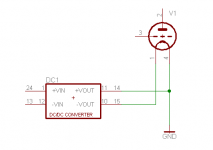
I cobbled together a quick picture with a way to identify terminals in order to avoid any potential confusion 🙂 I used a DC-DC converter as a quick replacement for "black box" filament voltage regulation module and wired it the same way it is done in schematic on page 6 (with V+ connected to amplifier's ground potential).
The "more positive end of the module output" being 11-14 in my picture: it is connected to terminal 4, which according to you should be the "more negative end of the filament" (and vice versa). This is just not how physics works; terminal 1 will be at lower potential (hence "more negative") than the other end of the filament. It is the polarity of the filament supply that determines which end of the filament is more positive and which more negative, not you.
I'm not sure what you're up to with that but you're trying to convince people that basic laws of nature have changed just to accomodate your whim 😕
Done.
It appears that it is you who doesn't understand what is going on. In a directly heated tube one portion of the filament will inevitably be at higher potential than the other. As long as Va-k is large enough, this is a non-issue. However when anode voltage is low some unwanted effects might occur.
One example of relatively low anode voltage DH tube would be a VFD display. Filament voltage of 5V and anode voltage of 20V is nothing uncommon. If heater is connected as pictured above there will be Va-k of 20-25V. If negative lead of the filament suuply is connected to the ground, Va-k will be 15-20V. Lower V-ak means lower current (which directly translates into lower light output for VFD, an effect that is visible) and what's worse, uneven current ratio between the two ends of the filament means display will also be uneven (one portion of each segment will be brighter than the other, which is also VERY visible) and filament will - at least in theory - be destroyed faster due to uneven current draw. One common remedy to this problem is the use of balanced filament supply, either center-tapped AC at high enough frequency (f flicker/hum isn't an issue) or split DC (if it is).
Therefore - as stated in my previous message - this disparity between the outermost ends of the filament is reduced by keeping Va-k as large in comparison to the voltage across the filament as possible. However with large anode voltages of audio amplifiers (few hundred volts above cathode) this is hardly an issue so connecting filament supply the other way around (with portion of filament held above ground of the amplifier) doesn't change much; it is a matter of few per cent, if that. For example (2A3 values picked from first datasheet I came across), if Va = 250V and Vf = 2.5V, changing the connection changes the ratio (Va-k+ / Va-k-) from 0.9901 to 0.9900 (0.01%) and drops the Va-k by 1%. Mains voltage changes throughout the day will cause more change than this.
Can somebody hear the difference ? Beats me. I'm pretty sure I can't 😀 I can explain the difference between one and the other though.
Drop author a line and ask him for explanation if you cannot stomach mine. I am completely confident you will receive confirmation of what I wrote here.
Why thanks and right back at you 😉 I sure could use some.
The module supply is floating, and the more positive end of the module output is attached to the more negative end of the filament, and vice versa. It is not just drawn that way, but done with deliberation. This is not an issue, it is simply a fact.
The "more positive end of the module output" being 11-14 in my picture: it is connected to terminal 4, which according to you should be the "more negative end of the filament" (and vice versa). This is just not how physics works; terminal 1 will be at lower potential (hence "more negative") than the other end of the filament. It is the polarity of the filament supply that determines which end of the filament is more positive and which more negative, not you.
I'm not sure what you're up to with that but you're trying to convince people that basic laws of nature have changed just to accomodate your whim 😕
On that subject see thread http://www.diyaudio.com/forums/tubes-valves/38248-new-dht-heater.html . Fdegrove asks the question in post 31 and Guido Tent (the module designer) replies in post 34. However you will be better informed if you read the whole thread.
Done.
It appears that it is you who doesn't understand what is going on. In a directly heated tube one portion of the filament will inevitably be at higher potential than the other. As long as Va-k is large enough, this is a non-issue. However when anode voltage is low some unwanted effects might occur.
One example of relatively low anode voltage DH tube would be a VFD display. Filament voltage of 5V and anode voltage of 20V is nothing uncommon. If heater is connected as pictured above there will be Va-k of 20-25V. If negative lead of the filament suuply is connected to the ground, Va-k will be 15-20V. Lower V-ak means lower current (which directly translates into lower light output for VFD, an effect that is visible) and what's worse, uneven current ratio between the two ends of the filament means display will also be uneven (one portion of each segment will be brighter than the other, which is also VERY visible) and filament will - at least in theory - be destroyed faster due to uneven current draw. One common remedy to this problem is the use of balanced filament supply, either center-tapped AC at high enough frequency (f flicker/hum isn't an issue) or split DC (if it is).
Therefore - as stated in my previous message - this disparity between the outermost ends of the filament is reduced by keeping Va-k as large in comparison to the voltage across the filament as possible. However with large anode voltages of audio amplifiers (few hundred volts above cathode) this is hardly an issue so connecting filament supply the other way around (with portion of filament held above ground of the amplifier) doesn't change much; it is a matter of few per cent, if that. For example (2A3 values picked from first datasheet I came across), if Va = 250V and Vf = 2.5V, changing the connection changes the ratio (Va-k+ / Va-k-) from 0.9901 to 0.9900 (0.01%) and drops the Va-k by 1%. Mains voltage changes throughout the day will cause more change than this.
Can somebody hear the difference ? Beats me. I'm pretty sure I can't 😀 I can explain the difference between one and the other though.
Drop author a line and ask him for explanation if you cannot stomach mine. I am completely confident you will receive confirmation of what I wrote here.
Good luck Mr. Arnulf.
Why thanks and right back at you 😉 I sure could use some.
Attachments
The simple answer to this question is "read the 26 preamp thread". There are comprehensive instructions and schematics for DC supplies to DHTs. Rod Coleman is a master at this - those who have tried his designs rave about the sound quality (and I'm one!)
andy
andy
I cobbled...
[snip]
Mr. Arnulf,
Again you miss my point. (You also misinterpreted the meaning of my labels of ‘more positive’ etc.).
Let me try another way...
1.
The original poster wants to know if the Tent modules can be copied.
2.
In order to copy anything one must first understand its application.
3.
With regard to the application, the module designer has arranged for a particular order of connections.
4.
The order of connections provides a DC current flowing in one direction from the high tension supply and a heater current flowing in the other direction. The total is the difference between the two. Not the sum of the two.
5.
Arranging a difference and not a sum was deliberately done by an intelligent and experienced module designer.
6.
As it was done deliberately it is likely to affect the application performance.
7.
As it is likely to affect the performance then it is worth while making the time and effort to understand the reason why it is connected in this way.
8.
Once the design is fully understood it can be successfully copied, or maybe even improved upon.
That was my underlying point.
Have a nice day.
OK, I asked the original designer of the Hagtech Clarion 2A3 (the one I am building), Jim Hagerman, what his opinion was on using DC in place of his design (balanced cathode drive). His response.....basically, stick with the balanced cathode drive. I also asked another friend of mine who is prolific on these forums and sells kits commercially what his thoughts were on these kits I referred to........basically he believes these are 'gold plated snake oil' sold at x10 their value.
At the end of the day I think I will build it as originally designed, seems how I already have the 2.5vct Hammond transformers on hand. If I think it needs improvement, I am going to build a very basic rectifier/filter and try that......still not satifsfied I might then try something as complex as these modules.
Thanks for the lively discussion!
Jeff
4.
The order of connections provides a DC current flowing in one direction from the high tension supply and a heater current flowing in the other direction. The total is the difference between the two. Not the sum of the two.
No, it isn't, and that's precisely the bit that you don't seem to understand and I've been trying to clarify for you. Have a look at page 6 of this document you referred us to up there again and omit the optional 10R resistor for easier understanding: V+ is connected to amplifier ground. V- is connected to the other end of the filament. Va-k at "left" end of the filament is Va + Vf (which is short way of saying Va - -Vf). Va-k at the "right" end of the filament is Va.
If voltage at "+" terminal is at higher potential than that at "-" terminal of the module - as the markings on PCB would suggest - then what you are claiming there defies the laws of physics. You don't have to take my word for it either: whip out a voltmeter and test it yourself, just spare us the silly claims.
You don't even need the tube or a substitute circuit, you only need two independent power supplies or batteries. Connect "+" terminal of the bottom supply/battery which stands for filament supply module to the "ground" (= negative terminal of top battery) and measure the voltage across both - you will notice it is the sum of the two, not the difference.
If you wanted it to behave the way you describe it, you'd have to connect the end of the filament connected to "-" output of the filament regulation module to the amplifier ground. This would make Va-k at the "left" side equal Va and the "right" side Va - Vf.
No argument on the rest of your points though, except #8: I described the difference between one and the other but I cannot describe a measurable effect (if any) it has on the sound. As the connection is trivial enough (there are only two ways to connect the filament supply module, assuming tube is built symmetrically with regards to the plane intersecting the filament in the middle, which is a reasonable assumption) one can easily test both variants and settle for one that he prefers better - again assuming one can actually detect any difference. The author himself indicated that in the post you pointed me to.
@jmillerdoc: this is not a complex circuit when there is ample input voltage to play with. Have a look at Geek's post further up this thread for nice schematics, I'm sure anybody here can build one of these themselves by referring to it. Since you already own a CT transformer it is even more trivial to create a balanced DC supply which employs the best of both words, namely even filament heating and no AC hum due to heating/cooling each quarter of the cycle due to output regulation. The only downside of that particular transformer is that there isn't enough headroom to use integrated voltage regulator with 2.5V windings so you'd have to use discrete current source and low drop (schottky - SB3xx series comes to mind) rectifiers. Heck, I can put together a schematic and possibly a PCB if anybody is interested.
If you forego regulation as you suggested in your message, there is still the upside that whatever residual there is left after passive filtering, it balances itself as long as you use full wave rectification on both half-secondaries.
Last edited:
will notice it is the sum of the two
When you say sum you intend to add them? So you claim that if 100 mA is flowing in one direction and 500 mA in the other direction then they sum to make (100 + 500 =) 600 mA ?!?!
Surely you can see that is not the case.
Or perhaps your interpretation of 'sum' means add a current in the opposite direction as a negative value, in which case you end up with the difference, which is exactly what I meant and said.
I think this is perhaps a joint misinterpretation of each-other's notation.
Oh well.
Actually I don't have time for this.
Goodbye thread.
The reason for connecting to the positive end of the filament to ground is to try and even out the effect dc has on directly heated tubes. One end of the filament will emit more electrons than the other. Compare that to alternating current. Look at some old tube manuals and you'll see the same thing.
Ok, another question...the amp I am in the process of building the Hagtech Clarion 2A3
here: CLARION 2A3 Stereo SET Amp (follow link to article on that page)
He is using 2 separate filament supplies for a balanced cathode drive and no hum pots. Is this better than a filtered DC supply on the filaments....am I gaining or losing anything by rectifying the filament heater supply?
It just seems to me that a good filtered very low ripple heater supply would be better than anything AC, even this balanced cathode drive.....but I never fail to be suprised by what I learn. BTW this is my first DHT amp to build and I just want it to be one of the best I have built too.
Jeff
I think that is nothing more than a 2.5VCT filament transformer which is exactly the same thing I used in my 45 and 2A3 amplifiers. I would try this first - my experience has been that 2.5V tubes work fine on AC and you can achieve hum and buzz levels at the output of <2mVrms without difficulty with this circuit. I am a big fan of CCS based heating for DHTs but have found it only necessary at filament voltages of 4V or greater in power amplifier output stages. (DHT pre-amps are a different matter, and even 1.5V filaments need very clean dc.) The one potential benefit is using dc heating will eliminate low level intermod products (distortion) in the output stage due to the ac filament supply. It is a subtle effect, but it is there. (Primarily 120Hz product/difference on 60Hz supply IIRC) You can see sidebands with an FFT of a single tone if your amplifier and acquisition hardware (soundcard usually) noise floor is low enough. Not sure practically speaking that this is much of a reason for concern.
Last edited:
- Status
- Not open for further replies.
- Home
- Amplifiers
- Tubes / Valves
- DC modules fot DHT amps....too expensive to buy pre-built, why not DIY them?