I would have expected the DC volts at the emmitters of Q5 and Q15 to be nearer zero, so that does sound like an imbalance, although the vital final result is that the DC voltage at the speaker output is zero.
The DC voltage across C3 seems a little low, and that would explain the 0.1 volts across the two 47 ohm resistors.
To be honest, the whole design seems to run a little on a knife edge and is totally dependant on the properties of the devices used.
How do those voltages compare with the "good" channel.
First thing is that 0.1 volts across R3 and R31 is not enough to turn the output transistors on.
Are you saying that the outputs get hot with this 0.1 volts present... they should be totally cold at that. If they are not then there is a problem around the outputs.
The voltage across R1 and R2 is correct.
Can you measure also the DC voltage across R14 and R32
thank you,of course i can 🙂 ,the dc across R14= -0.6 and R32= 0.6.
if there is not enough voltage to turn output transistor on,so what should i do?
I'll look in again later today 🙂.
The two resistors (in either circuit) determine how hard the input transistors conduct.
If it's like the first diagram then replacing one of them with a pot (temporarily) may be an idea to help set the "current" or more correctly the voltage that appears across each transistor.
If it's like in the second then BOTH resistors would need replacing with pots to both set the current and trim the output to zero.
You need around 4 volts across C3 to get the outputs conducting and it's quite critical, a few tens of millivolts either way is the difference between no current flowing and overheating the outputs.
I would have expected the DC volts at the emmitters of Q5 and Q15 to be nearer zero, so that does sound like an imbalance, although the vital final result is that the DC voltage at the speaker output is zero.
The DC voltage across C3 seems a little low, and that would explain the 0.1 volts across the two 47 ohm resistors.
To be honest, the whole design seems to run a little on a knife edge and is totally dependant on the properties of the devices used.
How do those voltages compare with the "good" channel.
compare to the "good" channel,the voltage almost the same,with resistors value 12k for R18 and R19,the dc offset on speaker output are rather low for both channel,0.4 vdc for good channel and about 0.55vdc for "bad" channel.
but both channel are the same,they produce poor sound quality.
Mooly,if this design totally dependant on properties devices,do you have an advice,what should i change?,the transistors maybe?
thanks
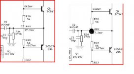
Looking at the circuit can you confirm that the two resistors R18 and R19 are connected as drawn OR does the junction of the two resistors go to the emmiters of Q5 and Q15 like this.
Which is it ?
no,they aren't connected at 0R,their position like on left side picture
I'll look in again later today 🙂.
The two resistors (in either circuit) determine how hard the input transistors conduct.
If it's like the first diagram then replacing one of them with a pot (temporarily) may be an idea to help set the "current" or more correctly the voltage that appears across each transistor.
If it's like in the second then BOTH resistors would need replacing with pots to both set the current and trim the output to zero.
You need around 4 volts across C3 to get the outputs conducting and it's quite critical, a few tens of millivolts either way is the difference between no current flowing and overheating the outputs.
Thanks Mooly🙂
yes,they like first diagram,and i was ever use this methode,changing one resistor with pot and i set till the total value for resistor and pot =14k,their sound still poor,and i down again into 13K,and.. after three minutes the output transistors blew
I think the first thing is to replace one of the resistors, either R18 or R19 with a pot, say 22k and tweak this to give around 0.047 (47 millivolts) across R5. That will give a current of around a 100 ma.
Start with the pot at MAX resistance (22k) and adjust slowly.
Then see what the DC offset is, and what can be done to improve it from there.
You might be as well to put a 100 watt bulb in series with the mains too as this will stop large currents flowing and blowing the outputs.
Start with the pot at MAX resistance (22k) and adjust slowly.
Then see what the DC offset is, and what can be done to improve it from there.
You might be as well to put a 100 watt bulb in series with the mains too as this will stop large currents flowing and blowing the outputs.
I think the first thing is to replace one of the resistors, either R18 or R19 with a pot, say 22k and tweak this to give around 0.047 (47 millivolts) across R5. That will give a current of around a 100 ma.
Start with the pot at MAX resistance (22k) and adjust slowly.
Then see what the DC offset is, and what can be done to improve it from there.
You might be as well to put a 100 watt bulb in series with the mains too as this will stop large currents flowing and blowing the outputs.
thanks Mooly,i will try,and is this adjustment still with valve stage disconnect?,and the input to junction of emmiter q5 and q15 connect to the ground?
Yes valve stage disconnected.
DO NOT connect the emmiters directly to ground, I would leave floating, with just R34 and C1 as shown on circuit.
DO NOT connect the emmiters directly to ground, I would leave floating, with just R34 and C1 as shown on circuit.
Hi Tiefbassuebertr
i have try your schematic,with 5k resistors between q5 and q15 as on your schematic,the output transistors run very hot quickly,no more than two minutes after the amp turn on,is it no problem? and also one channel have 40vdc on speaker output,but if i change the resistor to 10k,the dc is reduce till a few hundred mv,any advice?
thanks very much
this 5K resistors (in your schematic 12K) are matched for the appropriate idle current through the output by simulation, not in reality through the spread in Vbe parameter !!!
In real life you must use a potentiometer - at best the spindle version. After reach the appropriate idle current, you can desoldering this potentiometer and replace through a resistor network with exact the same adjusted potentiometer value.
Independend of this, here some advices for troubleshooting :
At first, replace Q5/15 though BD 139/BD140 for heatsink mounting for better thermal connection
perform DC test by your circuit
1) without Q9/8 and Q2/1 (i. e. as buffer only Q6/4) and as load only a zobel network. Check the variations range of voltage for idle current about a 10 K pot instead of 2x 5 K
2) after correct DC conditions add Q9/8 and check the variations range of voltage for idle current again. Reduce idle current voltage to the lowest value
Until this time you don't risk damage of Q2/1
3) add Q2/1 after correct DC conditions. Turn on the potentiometer for approx 20mA idle current through Q2/1
Last edited:
this 5K resistors (in your schematic 12K) are matched for the appropriate idle current through the output by simulation, not in reality through the spread in Vbe parameter !!!
In real life you must use a potentiometer - at best the spindle version. After reach the appropriate idle current, you can desoldering this potentiometer and replace through a resistor network with exact the same adjusted potentiometer value.
Independend of this, here some advices for troubleshooting :
At first, replace Q5/15 though BD 139/BD140 for heatsink mounting for better thermal connection
perform DC test by your circuit
1) without Q9/8 and Q2/1 (i. e. as buffer only Q6/4) and as load only a zobel network. Check the variations range of voltage for idle current about a 10 K pot instead of 2x 5 K
2) after correct DC conditions add Q9/8 and check the variations range of voltage for idle current again. Reduce idle current voltage to the lowest value
Until this time you don't risk damage of Q2/1
3) add Q2/1 after correct DC conditions. Turn on the potentiometer for approx 20mA idle current through Q2/1
Hi Tiefbassuebertr
thank you very much for the advice 🙂,i will try this way you give,and will inform the result to you immediately
once again,thank you
Hi Tiefbassuebertr,
I like this buffer.
Though, i do not understand how thermaltracking is done here.
Do you know if it should be possible to upscale to 90volts rails.
I have a bunch of sankens A1995/C3264
A1294/C3263 (drivers)
A1837/C4793 (pre-drivers)
These triples are used in the Rotel RB990 with 90 volts rails and quads outputs.
What could i use for Q16/17?
Thanks in advance
Thermaltracking? whats this? mean you thermal compensation (stabilizing of idle current)? Q5/15 must be mounted on the same heatsink as output power BjT devices
If you look to the SOA of all me known BjTs, I cannot really recommend +/- 90V for output stages (you must realize a very wide range of protection requirements and massive paralleling output devices - as usual by amps for public address, e. g. Dynacord). Best choice is max +/-40V supply voltage and computer grade capacitors with 63VDC and not 40VDC or 50VDC. Sikorel (EPCOS) Rifa, BHC so as F&T is a good choice. go to
http://www.diyaudio.com/forums/solid-state/653-computer-grade-capacitor.html ).
If you want more power, choice bridge mode and/or one amp for each frequency range (actice crossover or at least bi/multi amping).
Last edited:
Thermaltracking = stabilizing of idle current. Yes
How can you say this?
Many amps on the market have higher than 50v rails .
I meant RB 1090 ( not 990) This one have 90v rails.
Mode d'emploi ROTEL RB-1090-3 - Notice ROTEL RB-1090-3 - Anglais - Diplodocs.
This is an example.
I agree bridging is also a good way. Cascoding the output devices is also possible.
I already use triamping and electronic crossover.
...I just own big transformers and caps that i would like to use for subwoofers powering.
I have also 16 pairs of high power Sanken BJTs. Huge heatsinks too.
Thanks anyway.
Last edited:
Thermaltracking = stabilizing of idle current. Yes
How can you say this?
Many amps on the market have higher than 50v rails .
I meant RB 1090 ( not 990) This one have 90v rails.
I just own big transformers and caps that i would like to use for subwoofers powering.
I have also 16 pairs of high power Sanken BJTs. Huge heatsinks too.
Thanks anyway.
Except Rotel many other uses such voltages, in some cases up to +/- 130V. Nevertheless I say the same as above mentioned. For a sub woofer power amplifier the half voltage as nornal used are more as enough. The loss in peak output power there is only -6db - not too much (quarter of the initial output power is less loss than most believe).
I prefer high efficiency sub woofer as you can see on my website (english = shortforn, scoll down about button "Einstieg")
The solid installed subwoofer from photo about the follow ebay website needs only 10 watts peak power (6x '18, cabinet volume 2.400 liters) This project was realized by a customer of me in Friederichshafen, some years ago
Kosteneinschätzung für ultimatives Subwoofer System bei eBay.de: Lautsprecher (endet 09.11.09 16:22:39 MEZ)
The contrary part for extrem input power and low acoustical output power (low efficiency) is follow:
:: Ground Zero :: Subwoofer / GZNW 15SPL
special made for tight and clear bass transmission in small cabinets (e. g. car hifi)
When you transmit a small spectrum (20-60 Hz e. g.) +/-40V supply voltage (that means at the same time 35Vss output voltage) are still enough because their lower voice coil impedance than normal hifi resp. public address loudspeakers.
What's your subwoofer transducer model ?
Last edited:
My woofers are: 2 X Peerless xxls 12" 8ohms/75 liters closed boxes
Riviera Acoustics - 12" XXLS Subwoofer
Unfortunately your ebay link is dead.
I already own a 2x200w nice amp and some others (2 x Audiolabor ES200 etc...), but i have fallen, some time ago into the "buiding of amps" trick (3 x Nelson Pass F5, 4x100w quasi complementary).
I am now planning to build a monster amp, just for fun. Or may be just power buffers, in order to try different front ends.
..I am curious of every "exotic" design.
My woofers are: 2 X Peerless xxls 12" 8ohms/75 liters closed boxes
Riviera Acoustics - 12" XXLS Subwoofer
Unfortunately your ebay link is dead.
I already own a 2x200w nice amp and some others (2 x Audiolabor ES200 etc...), but i have fallen, some time ago into the "buiding of amps" trick (3 x Nelson Pass F5, 4x100w quasi complementary).
I am now planning to build a monster amp, just for fun. Or may be just power buffers, in order to try different front ends.
..I am curious of every "exotic" design.
Also a good choice, if large cabinet volumes not to realize. The choice of closed system is also the best by such little cabinet.
I will make a simulation about xxls12 by your used 75 liter, for looking a good choice of Amplifier.
I don't understand the reason for death ebay URL, (here in Germany it isn't death for approx 2 months) but I think, the reason is by external servers. Please try follow:
go to eBay: Neue und gebrauchte Elektronikartikel, Autos, Kleidung, Sammlerstücke, Sportartikel und mehr – alles zu günstigen Preisen (or "www_ebay_de" - replace dots !!!) and fill in the item No "320442499161" about "Artikelnummer"
Last edited:
- Status
- Not open for further replies.
- Home
- Amplifiers
- Solid State
- Help with this amp