Hello,
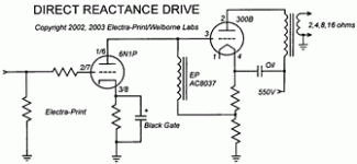
I was wondering if there is a formula that would allow me to calculate the -3db point change in bass response if I increase the cathode bypass resistor from the current 100uF to say 270uF changing nothing else? I have the values for the tube (mu, etc) and cathode resistor as per the diagram below (6N1P tube). I assume this change will lower my -3db point from some value down to some new value and before spending on caps I just wanted a ballbark idea to see if it was worth it.
Thanks
paba
Attachments
You'll have to get out your calculator, since there are several variables in the expression. I'm going to do this with an image, since ascii math is cumbersome for this sort of stuff

If you need to know more about the net impedence of the cathode resistor/bypass capacitor parallel circuit, say so and I'll continue when I get home from work.
Aloha,
Poinz

If you need to know more about the net impedence of the cathode resistor/bypass capacitor parallel circuit, say so and I'll continue when I get home from work.
Aloha,
Poinz
Hello,
I was wondering if there is a formula that would allow me to calculate the -3db point change in bass response if I increase the cathode bypass resistor from the current 100uF to say 270uF changing nothing else? I have the values for the tube (mu, etc) and cathode resistor as per the diagram below (6N1P tube). I assume this change will lower my -3db point from some value down to some new value and before spending on caps I just wanted a ballbark idea to see if it was worth it.
Thanks
paba
Unfortunately it is not so simple! Where cathode bypass caps are concerned, there is not always a -3dB cut-off frequency in the conventional sense, because the gain of the stage does not fall indefinitely. Depending on the valve used, and the value of the resistances, there may be less than 3dB difference between the unbypassed and fully bypassed levels of gain!
A better way to define it is by the 'half boost frequency'. The formula for this is given in this article:
http://www.freewebs.com/valvewizard2/ChoosingBypassCaps.pdf
I think this excel sheet will do what you want. Look for tubeformulas.xls
joeltunnah.com
otherwise formulas.xls on this page
http://www.vt52.com/diy/tips/tips_software.htm
joeltunnah.com
otherwise formulas.xls on this page
http://www.vt52.com/diy/tips/tips_software.htm
Last edited:
Ok thanks all,
I will get by abacus out and pencil and paper and see how far I can get.
I don't have my Welborne schematic here now to get some of the Resistor values needed as inputs.
cheers
paba
I will get by abacus out and pencil and paper and see how far I can get.
I don't have my Welborne schematic here now to get some of the Resistor values needed as inputs.
cheers
paba
ok,
spent more time on this and found this on a web site..
"If the bypass capacitor is used, its value can be determined using the capacitive reactance formula see *below, and the value of Rk. You must decide what the frequency response of the cathode-bypassed circuit will be. The formula tells you where the response is down by 3db.
*f = 1/(2pi x Ck x Rk) and Ck = 1/(2pi x Rk x f)
As an example, for a 500-ohm cathode resistance and a 70Hz 3db down point, Ck is under 5 microfarads. "
So punching in the values I have in my DRD amps today...
gives be a -3db frequency of 10.6 Hz for that 6N1P first stage.
changing to a cap value of 220uF just as example, would mean a -3dB point of 4.8Hz
330uF -> 3.2 Hz
390uF -> 2.7 Hz
Well, I conclude that it isn't the difference between 10.6 Hz and 4.8Hz that will make the cows come home. Although I suppose that I could implement a quick toggle switch to alternate between two cap values and see if it is even audible at the speaker end.
Source:
Cathode-Bias and Fixed-Bias Switching in Tube Power Amplifiers
Last edited:
- Status
- Not open for further replies.
- Home
- Amplifiers
- Tubes / Valves
- formula help
