A local guy picked up a pre which he now has issues with an brought it to me.
It uses one of those DIY-GENE regulated supply boards that take that Chinese
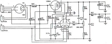
6Z4, a 12B4 and a 12AT7 in it's supply.
2 different 6Z4 rectifiers exhibit the usual things when there dying/dead with a
nice fireworks in the bottle, have 1 more to try, but no way to test the things
on any of my testers (that I know of yet) before trying the last one he has I'd
looked over the circuit, it has a 180uf cap hanging right off the rectifier so it's
a cap input supply with a LARGE cap on that input.
Now I wouldn't go anywhere near that amount even on a 5AR4 let alone a 6X4
size rectifier like this 6Z4, so am I to assume this thing is just eating rectifiers
with that 180uf cap hanging there or am I missing something?
I've found a few different schematics for this same supply board and they all
pretty much use in that 200uf range on the cap input supply.
From everything I've done in the past tells me this is a flawed arrangement, no?
Now I could modify the circuit and put say a 100ohm resistor on that input or go
and change the first cap to a small poly then use a new rectifier and I should be
fine but I'm just finding it at least a touch difficult to believe how this was done.. 😕
(following that first stage is an RC stage of 500ohm and another 180uf cap)
Attached is the same basic supply.. any thoughts?
It uses one of those DIY-GENE regulated supply boards that take that Chinese
6Z4, a 12B4 and a 12AT7 in it's supply.
2 different 6Z4 rectifiers exhibit the usual things when there dying/dead with a
nice fireworks in the bottle, have 1 more to try, but no way to test the things
on any of my testers (that I know of yet) before trying the last one he has I'd
looked over the circuit, it has a 180uf cap hanging right off the rectifier so it's
a cap input supply with a LARGE cap on that input.
Now I wouldn't go anywhere near that amount even on a 5AR4 let alone a 6X4
size rectifier like this 6Z4, so am I to assume this thing is just eating rectifiers
with that 180uf cap hanging there or am I missing something?
I've found a few different schematics for this same supply board and they all
pretty much use in that 200uf range on the cap input supply.
From everything I've done in the past tells me this is a flawed arrangement, no?
Now I could modify the circuit and put say a 100ohm resistor on that input or go
and change the first cap to a small poly then use a new rectifier and I should be
fine but I'm just finding it at least a touch difficult to believe how this was done.. 😕
(following that first stage is an RC stage of 500ohm and another 180uf cap)
Attached is the same basic supply.. any thoughts?
Attachments
It is clearly a faulty design. Probably originally intended for use with a solid state rectifier and later some moron tweaked it for better sound and it didn't blow straight away 🙂
Eeeeek! 😱
I can see several things wrong with that straight away too.
Even if the rectifier survives with that much capacitance, how on earth does the regulator do its job with C12 so high and C10 so small? Not to mention R22 being a good 1/10 the size it should be and the circuit would likely be more stable without C19.
Cheers!
Thanks guy's for the reassurance.. Now to decide how I'm going to proceed..
Except for the errors previously pointed out this design is not too different from the one I was using 20yrs ago. It can perform well.
The input cap needs to be much smaller, presumably one might get away with the huge input cap if the winding resistance of the high voltage secondary was quite high.
As Geek points out:
Remove C19 - it massively rolls off the ac gain in the error amplifier reducing feedback margin and therefore needlessly raises the output impedance.
Increase C10 in value to about 0.047uF - 0.1uF, note that some claim larger values appreciably affect LF performance in a negative way. I often leave these out depending on implementation because in specific instances it seems to sound better.
-
Replace C19 with a nice film cap of 10uF or less.
Consider cutting an etch, replacing R22 with a 100K resistor and powering from the unregulated side of the supply. Were I to do this I would probably also replace R19 with a 5H choke.
Last edited:
Thanks for the input guy's.
I don't have a lot of regulated supply experience, especially one like this.
(comments are much welcome)
Yah power tranny resistance is up there, 270ohms from each leg to center
tap, but I still wouldn't want that much capacitance on these tiny rectifiers.
I'll probably spice Sim this thing and learn a bit more about it, now in 1 place
it was said to remove C19, in another replace it with a film cap 10uf or less?
If it were mine, yah I'd be substituting R19 with choke, not sure I follow the
part about R22 and where to power it from/hook it back in though.
Leaving C10 out just means removing it an doing nothing else to the circuit?
Hi Kevin,
You mean C12?
Cheers!
Replace C19 with a nice film cap of 10uF or less.
You mean C12?
Cheers!
- Status
- Not open for further replies.
- Home
- Amplifiers
- Tubes / Valves
- Chinese 6Z4, also those regulated supplies.