Hello,
Here's a simple schematic of my opamp output.
Can anyone suggest any changes for the better? The resistors are the standard 5% type so I assume swapping them for 0.1% RC55Y's would be a start?. Going on the 'less in the path' approach; do I need them all? can I remove a couple and only have 1? if so, what value would be ideal?
I removed all the resistors at one stage and the output became far to mellow so back in they went.
The caps were removed at another stage but it seemed to lack something, although I'm unsure what, So they went back in too.
I know black gates would be good but I'm looking into plastic film. There's a bit of space so it wouldn't be a problem. Anyone suggest a value/brand of plastic cap to replace the ZA??
Thanks in advance,
Ant
Attachments
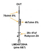
Not sure why the 4k7 parallel with 75R is there, was there a muting circuit that you have now removed?
It's pointless using 0.1% tolerance resistors for this application.
It's pointless using 0.1% tolerance resistors for this application.
An electrolytic cap... hmm, I don't know. Better use a space-saving Wima MKS2 4.7uF 63V, for instance.
Also I'd remove all those resistors and connect the capacitor to the output with something like 100 ohm.
Also I'd remove all those resistors and connect the capacitor to the output with something like 100 ohm.
Not sure why the 4k7 parallel with 75R is there, was there a muting circuit that you have now removed?
It's pointless using 0.1% tolerance resistors for this application.
Correct, I've removed the muting circuit. Why pointless?
Why do you have to a cap in the first place? Where does this signal go? What is your load?
I pressume it's a dc blocking cap?
An electrolytic cap... hmm, I don't know. Better use a space-saving Wima MKS2 4.7uF 63V, for instance.
Also I'd remove all those resistors and connect the capacitor to the output with something like 100 ohm.
A polyester cap? possibly. 1/4w carbon 100 ohm?
Thanks
OK the 4k7 was part of the muting circuit. You can get rid of everything and just use a 47 ohm 1/4 watt 1% metal film resistor and 47uF or so cap. Or if your input stage it is connecting to has a DC blocking cap you can remove this one.
0.1% tolerance resistors are pointless in this application because they don't affect the signal level to any real degree.
0.1% tolerance resistors are pointless in this application because they don't affect the signal level to any real degree.
OK the 4k7 was part of the muting circuit. You can get rid of everything and just use a 47 ohm 1/4 watt 1% metal film resistor and 47uF or so cap. Or if your input stage it is connecting to has a DC blocking cap you can remove this one.
0.1% tolerance resistors are pointless in this application because they don't affect the signal level to any real degree.
Thanks,
Andrea (post above) recommends a 100R, which do I go for???
A polyester cap? possibly. 1/4w carbon 100 ohm?
Thanks
If you want it small enough to fit the circuit, yes. I'm using the same Wima caps I've suggested (on a DAC's output) and I find them to be inaudible in the signal path.
You could use a 100 ohm (or also 200 ohm) 1/4W metal film resistor..
Last edited:
47 ohm will be fine unless you have stupid esoteric cable or long normal cable. 200 ohm is a bit high really.
47 ohm will be fine unless you have stupid esoteric cable or long normal cable. 200 ohm is a bit high really.
I'm running Soniclink Violets, so I guess 47r will be ok. Can I not just remove 1 75r and the 4k7 and leave the 75r??
I don't believe in the usefulness of a very low output impedance -- better keep the opamp isolated from any capacitive load. But 75 ohm should be enough for that.
Hi,
I know the point of the caps is to block DC on the output.
What's the point/advantage of having a resistor in the line?
Pete
I know the point of the caps is to block DC on the output.
What's the point/advantage of having a resistor in the line?
Pete
As Andrea has said it "buffers" the op-amp from the capacitive cable by adding a resistive part of the load it sees that dominates over the capacitive load.
Hmm, don't think so... unless you have some stupid esoteric cable 🙂200 ohm is a bit high really.
Many commercial players even have 470 ohm, often followed by a small parallel cap (for further filtering).
But yep, 100 ohm might be the most reasonable value when no further filtering is needed.
I did an investigation into the best sounding output resistor a very long time ago when I worked for Meridian Audio. This was a completely non scientific test. i.e it was done sighted and relied on my ears.
I tried with a number of different impedance cables and found that the system seemed to sound best with the impedance at the output of the source the same as the characterisitic impedance as the cable. It didn't sound best with no output resistor which is what I was expecting. It seemed to get very slightly worse as you moved higher. However this is really subjective stuff and I could easily have been decieving myself.
To this end since most HIFI cables at the time were approximately 50R impedance we used a 47R resistor. However we were using OPAMPs that could drive into a 47R short ciruit so were safe with this low output impedance. If yours aren't I'd recomend using something high emough to protect them.
I have no good rational for this as the frequenicies are far to low to be affected by any reflections on the cables and unfortunatley as is often the case in a comercial situation we did not have the time to do a further investigation.
Regards,
Andrew
Interesting, thanks for sharing it.
In past experiments I noticed that the series resistor has a significant effect on sound quality, and especially the combination of it and the (following) parallel high-cut capacitor, when present; even when the cut frequency is muuuch above the audio range.
In past experiments I noticed that the series resistor has a significant effect on sound quality, and especially the combination of it and the (following) parallel high-cut capacitor, when present; even when the cut frequency is muuuch above the audio range.
Last edited:
- Status
- Not open for further replies.
- Home
- Source & Line
- Digital Source
- Help to 'better' output schematic??