Guys.. I need help.
I made my DIY speakers and need help determining the frequency response. I am willing to donate $25 to you or to DIYaudio if anyone can send me a simulated frequency response (graph from 250Hz to 40kHz on db scale) for my mids and highs. Also impedence plots if possible
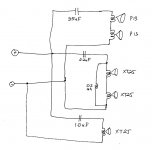
My speaker is a mutli-amped multi driver system. (see attached schema for mids/highs)
Low's 4x TB 740 8" woofers
Mids 2x Vifa P13's
Tweets 2x Vifa XT25's (4 ohm)
Super Tweet 1x XT25
The mids/tweets/STweet is powered by the same amp, The woofer and subwoofer, have separate power amps.
I have a have tuned the speakers purely by ear. I am well aware of the pitfalls of doing so, hence my desire to see how far off I am from a flat response. I do expect dips and peaks... some of that I am willing to live with because of my own listening biases....
I would like someone to do a simulation of these drivers with these crossover values and let me know if a response can be simulated.
I know I need to reverse the polarity of the tweeters (2nd order), but if there are other improvements/ fixes you can suggest that would be great.
Also these are installed on an open baffle, and I forgot to label the polarity of the drivers, all are drawn so the positve (hot) terminal is up.
Thank you so much in advance!
I made my DIY speakers and need help determining the frequency response. I am willing to donate $25 to you or to DIYaudio if anyone can send me a simulated frequency response (graph from 250Hz to 40kHz on db scale) for my mids and highs. Also impedence plots if possible
My speaker is a mutli-amped multi driver system. (see attached schema for mids/highs)
Low's 4x TB 740 8" woofers
Mids 2x Vifa P13's
Tweets 2x Vifa XT25's (4 ohm)
Super Tweet 1x XT25
The mids/tweets/STweet is powered by the same amp, The woofer and subwoofer, have separate power amps.
I have a have tuned the speakers purely by ear. I am well aware of the pitfalls of doing so, hence my desire to see how far off I am from a flat response. I do expect dips and peaks... some of that I am willing to live with because of my own listening biases....
I would like someone to do a simulation of these drivers with these crossover values and let me know if a response can be simulated.
I know I need to reverse the polarity of the tweeters (2nd order), but if there are other improvements/ fixes you can suggest that would be great.
Also these are installed on an open baffle, and I forgot to label the polarity of the drivers, all are drawn so the positve (hot) terminal is up.
Thank you so much in advance!
Attachments
A simulation would be pure theory.
Suggest you invest in a low cost sound level meter. RS has them for about $50. Also get a test signal CD with 1/3 octave warble tones to play thru your speakers while you measure the response.
Suggest you invest in a low cost sound level meter. RS has them for about $50. Also get a test signal CD with 1/3 octave warble tones to play thru your speakers while you measure the response.
Better yet, buy a measurement microphone from parts express for $40 and use free software like Holmi Impuls or free version of ARTA to do a real FR measurements.
Parts-Express.com: Behringer ECM8000 Measurement Microphone | measurement mic measurement microphone mic microphone RTA RTA mic RTA microphone special-11-2-behr
Parts-Express.com: Dayton EMM-6 Electret Measurement Microphone | BLACK09 Dayton EMM-6 measurement mic measurement microphone mic microphone electret mic electret microphone speaker mic test microphone test mic recording mic recording microphone Audi
You'll need a cheap microphone amp as well.
Parts-Express.com: Dayton EMM-6 Electret Measurement Microphone | BLACK09 Dayton EMM-6 measurement mic measurement microphone mic microphone electret mic electret microphone speaker mic test microphone test mic recording mic recording microphone Audi
You'll need a cheap microphone amp as well.
Last edited:
A RS SPL meter is not a precision instrument. You can get a FR measurement, but there is no assurance of reasonable accuracy. Taking FR measurements by writing down point using warble tones or pink noise is a royal PITA/ An extra $50 or ~$100 (~$150 calibrated) will get you a mic & preamp with which you can do actual design.
A RS SPL meter is not a precision instrument. You can get a FR measurement, but there is no assurance of reasonable accuracy. Taking FR measurements by writing down point using warble tones or pink noise is a royal PITA/ An extra $50 or ~$100 (~$150 calibrated) will get you a mic & preamp with which you can do actual design.
Thank you all for your ideas.
Ron do you have any suggestions for a cheap and accurate mic + preamp. I think I already have a ECM8000.... came with my Behringer DSP-8024.
Can't anyone use the publisehd specs for the drivers and put them in some software and PRESTO!
Last edited:
I tried once, they were so weird that I was left scratching my head. Also tried the DSP-8024's auto EQ function to simulate an inverse FR that was weird too.. adjecent frequency bands had 24-25db differences... 
You will receive a PhD at the end of this thread...😀I tried once, they were so weird that I was left scratching my head. Also tried the DSP-8024's auto EQ function to simulate an inverse FR that was weird too.. adjecent frequency bands had 24-25db differences...
http://sub-source.com/tribute/images/rabbit_pancake.gif
I tried once, they were so weird that I was left scratching my head. Also tried the DSP-8024's auto EQ function to simulate an inverse FR that was weird too.. adjecent frequency bands had 24-25db differences...
This is why I've suggested Holmi. It has automatic gating which is very useful for a beginner (in measurements)
You can't just plug manufacturer's FR and impedance in the crossover calculator and expect perfect results because the crossover will have a significant effect on the phase of each driver there for an overlap and the summed up frequency response. The baffle, it's size and the driver placement will affect FR of the loudspeaker as well. Baffle step loss comes to mind as well. Off axis response can make the loudspeaker sound great or bad in the room depending on the crossover. So, no. You can approximate the results in the crossover design software but the real world measurements and understanding is the key to a great sounding system.
If you have ECM 8000 already, all you need is a Behringer or other cheap mixer. Make sure it has phantom power supply for mic. ECM 8000 is probably the best or one of the best inexpensive measurement microphones. You can also have it calibrated for $50 if I am not mistaken.
Thank you all for your ideas.
Ron do you have any suggestions for a cheap and accurate mic + preamp. I think I already have a ECM8000.... came with my Behringer DSP-8024.
Can't anyone use the publisehd specs for the drivers and put them in some software and PRESTO!
ECM-8000 is accurate enough iif calibrated (and sometimes when not)
A Rolls MP-13 is fairly affordable and doesn't have the issues with tone controls of the usual Behringer devices.
I tried once, they were so weird that I was left scratching my head. Also tried the DSP-8024's auto EQ function to simulate an inverse FR that was weird too.. adjecent frequency bands had 24-25db differences...
Welcome to the real world of loudspeaker design. You were probably looking at real data and wondering why it didn't look like the marketing stuff you see all the time. Why is that I wonder?
As a side question, the mids and tweeters are arranged in a verticle m-t-st-t-m arrangement... I would have expected a relatively wider sweet spot, but all I do is move my head (straff not pivot) 2-3 inches and the image shifts by 5-6 feet to one side of the speaker... any thoughts?
Need help... will pay for small service.😀
Things I would test before (unless your speakers are ok) something else:You will receive a PhD at the end of this thread...😀
1. Changing the inductor 0.2mH of the XT25, doubling it, e.g. 0.47mH, to match phase curves.
2. Unless you want to work/go with this xover configuration on the Vifa's P13, (1order/no xover), changing it for a good match with the tweeters is not a bad idea if you don't have a problematic amp (differences in impedance). So this would be joining a 2order to the P13's (1order/2order) with 1.0mH/4.7uF, of course if you make this you have to invert their phase also.
3. Also give complete location of these drivers (Vifa P13, Vifa X25) on the front baffle (x,y) and baffle size, also volume of your box (for the 2xVifa P13), for more accurate simulations and understanding of your set-up.
4. Question, that is bothering me, why you got a third tweeter. I know that it works well for the impedance curve and it might give you good dispersion. Want to know your reasons?🙂
I would have expected a relatively wider sweet spot, ... any thoughts?
Adjust your expectations. What you experinced is what I would expect.
Strange design choise
May never work properly
But you seem to have put a lot work into it, and spent serious money
Lets see what can be done about it
First, try and connect ALL tweeters in series, meaning no supertweet
Or try ALL tweeters in paralel, and with a series resistor
If it helps we can go on from there
It will change the series cap function as well
@inductor: can you pls email me at arifh(a)prodigy dot net
@tinitus: Seems like a reasonable approach, however I am on the road for a few weeks and cannot get to tinkering with it now....Will get to this in a few weeks... thanks
@tinitus: Seems like a reasonable approach, however I am on the road for a few weeks and cannot get to tinkering with it now....Will get to this in a few weeks... thanks
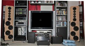
I guess a Picture of the prototype is also warranted...
The super tweeter is in design to compensate for my falling ear response over 16kHz ... (I know)...
3 tweeters in a line like that will comb filter like nobody's business, and the distance between your mids will cause a fair amount of cancellation off-axis as well.
Imaging can be room dependent - how close are the speakers to the side walls, is there any sound absorbent material at the specular reflection points?
No sound absorbent material on walls,
Side walls are 35" from each speaker.
Speakers toe'd in aggressively.
Mids/ Highs are OPEN BAFFLE.
Width of Baffle is 14" and the height of the open baffle area is about 27"
I will admit, they sound much different than the older design I had with 1 mid and 2 tweets in close proximity... I lost the image focus, but the mids are more lush and have less glare...
- Status
- Not open for further replies.
- Home
- Loudspeakers
- Multi-Way
- Need help... will pay for small service.