Hello all ,
I'm repairing a set of final 0.3 hybrid speakers.
But can't seem to get them fully ok, and since this is not my field of expertise seeking for help from the 'experts' 🙂
I replaced all capaciters in the EHT part , and have a bias voltage of 3kv now.
(checked with 1:1000 probe)
it has a EHT circuit with 8 capaciters and a input of 220v, so after comparing it to other circuits from wich i know the bias voltage this seems ok.
i checked the audio transformer with a scope and it's about 1:150 .
If i input 1,3v top-top i get 2x100v top-top on the outputs.
So this also seems ok.
If i connect it to the amp without powersupply , i get low (ofcourse normal woofer) and very little high.
If i then connect power , the high is about twice as loud...but still only the very high part...no midtones..and still not very much high tones.
so i have a beautifull speakerset with a hole in the sound..i got enough low...ok high but no mid.
Any idee's what can be the problem...can the ESL panels be defect...since a checked all other parts??
Thanks , arnold
hello ...
as far as i can tell, the membrame is origenal as it came from the factory.
so i have no idee..
i kind of suspect the ESL speaker panel , but i don't know how to test it.
as far as i can tell, the membrame is origenal as it came from the factory.
so i have no idee..
i kind of suspect the ESL speaker panel , but i don't know how to test it.
hello ...
as far as i can tell, the membrame is origenal as it came from the factory.
so i have no idee..
i kind of suspect the ESL speaker panel , but i don't know how to test it.
Sounds like you've done a good job checking out all the electronics. About all that is left is the diaphragm high resistance coating or connection to the coating. I'm not sure what method Final uses for connecting the bias voltage to the diaphragm and if it is accessable to check without tearing the panel apart. More often than not, it is the coating that has deteriorated with time, but I have heard of cases where it was just the contact that had corroded.
I see that ER audio sells a repair kit for the 0.3
Final 0.3 Repair Kit
thanks for the link to the kit...
wish there was a way to be sure it's the membrame, before buying the kit.
how many hours work is it to replace the membrame with a kit like that ?
maybe it's possible to get a working quad esl...but that one has a higher bias voltage (6kv) can i test it on the higher voltage...or will that destroy it for sure??
thanks....electronics no problem...but this is new for me..
thanks for the link to the kit...
wish there was a way to be sure it's the membrame, before buying the kit.
how many hours work is it to replace the membrame with a kit like that ?
maybe it's possible to get a working quad esl...but that one has a higher bias voltage (6kv) can i test it on the higher voltage...or will that destroy it for sure??
thanks....electronics no problem...but this is new for me..
One more thing to check concerning the HV bias supply. The connection to the diaphragm is usually made thru a very high resistance value resistor. I have seen these resistors fail open. Try bypassing it with a jumper to see if the panels spring to life. Additionally, you might check to see if the connection between the other side of the HV bias supply and the center tap of the step up transformers is made thru a resistor. If so, try bypassing it also.
Assuming these resistors are either not there, or test out OK here is a test you can try to gain some insight in to the health of your panels and their coating.
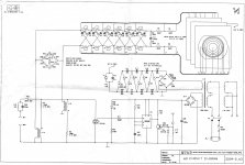
Assemble a charge indicator using a parallel combination of a high voltage capacitor and a neon bulb as seen in the middle of the Quad ESL63 schematic. The value of the capacitor is not terribly critical, I usually use a 1kV 0.02uF to 0.10uF.
1) Hook the output of the HV supply to one side of the charge indicator. The other side will get hooked up to the diaphragm contact wire in step 4)
2) Make sure the step up transformer is hooked up to the panel, and the other end of the HV supply is hooked to the center tap of the transformers.
3) plug in the voltage source for the HV supply and wait a few seconds for it to charge up
4) hook the diaphragm contact wire to the charge indicator and observe the neon bulb
- If all is well, the neon bulb will flash rapidly at first, and then slow down as the panel charges up, slowing down to something on the order of 1 flash per second for a typical panel.
- If the neon bulb flashes rapidly at first but never really seems to slow down, there is a short or leakage between the stators and the diaphragm
- If the neon bulb doesn't flash rapidly when the wire is first connected, there is either a problem with the diaphragm contact, or the coating has deteriorated.
Let us know what you find out, and we can go from there.
Attachments
@bolserst
Thanks , for that clear explanation.
I did as you told , and connected a neon bulb(with 47nf/2kv parallel)
in series with the hv.
The bulb doesn't do anything at all..
If i measure the voltage after the bulb with my 1:1000 probe the bulb flashes...so the current indication works i guess.
so any more off those clear tips to check the contacts or diaphragm ?
Greetings arnold.
Hi,
the membran coating of Final is a polymer in the dissipative range.
Actually final is not able to deliver any product. Some rumours say its due to coating issues.
I really think your coating isn't conductive anymore and you need to replace the membrane.
Capaciti
the membran coating of Final is a polymer in the dissipative range.
Actually final is not able to deliver any product. Some rumours say its due to coating issues.
I really think your coating isn't conductive anymore and you need to replace the membrane.
Capaciti
The bulb doesn't do anything at all..
If i measure the voltage after the bulb with my 1:1000 probe the bulb flashes...so the current indication works i guess.
so any more off those clear tips to check the contacts or diaphragm ?
With no charge indication at all, the odds are that the coating has deteriorated and is no longer conductive, as Capaciti mentioned above.
I'll add that contact corrosion problems are much less common.
Either way, you will have to take the panels apart to repair the problem.
With the panel apart and the diaphragm exposed, you can use the charge indicator to test the coating. Place two coins on the the coating about an inch apart. Connect one end of the HV supply to the 1st coin, and the 2nd coin thru the neon/cap charge indicator to the other end of the HV supply. If the coating is still conductive, the neon lamp should flash rapidly when the HV supply is turned on. Remember that usually only one side of the diaphragm has the conductive coating applied to it.
One more thing to check concerning the HV bias supply. The connection to the diaphragm is usually made thru a very high resistance value resistor. I have seen these resistors fail open. Try bypassing it with a jumper to see if the panels spring to life. Additionally, you might check to see if the connection between the other side of the HV bias supply and the center tap of the step up transformers is made thru a resistor. If so, try bypassing it also.
Assuming these resistors are either not there, or test out OK here is a test you can try to gain some insight in to the health of your panels and their coating.
Assemble a charge indicator using a parallel combination of a high voltage capacitor and a neon bulb as seen in the middle of the Quad ESL63 schematic. The value of the capacitor is not terribly critical, I usually use a 1kV 0.02uF to 0.10uF.
1) Hook the output of the HV supply to one side of the charge indicator. The other side will get hooked up to the diaphragm contact wire in step 4)
2) Make sure the step up transformer is hooked up to the panel, and the other end of the HV supply is hooked to the center tap of the transformers.
3) plug in the voltage source for the HV supply and wait a few seconds for it to charge up
4) hook the diaphragm contact wire to the charge indicator and observe the neon bulb
- If all is well, the neon bulb will flash rapidly at first, and then slow down as the panel charges up, slowing down to something on the order of 1 flash per second for a typical panel.
- If the neon bulb flashes rapidly at first but never really seems to slow down, there is a short or leakage between the stators and the diaphragm
- If the neon bulb doesn't flash rapidly when the wire is first connected, there is either a problem with the diaphragm contact, or the coating has deteriorated.
Let us know what you find out, and we can go from there.
There are lots of information about Quad ESL63 at Quad ESL63 electrostatic speaker service diagnose repair schematic manual. Its covers full details on QUAD ESL63 Full Range Electrostatic Doublet FRED Loudspeaker - Description, Service, Diagnose, Repair, Schematic Circuit Diagram and Owner Instruction Manual. Very useful info, hope it helps.
Hello all,
It has been a while..
Since the last posting i repaired a set of quad esl 's by replacing the membrame from the tweeter panel...and it worked 🙂
but now it's time for the final 0.3 speakers...but i have 6um and 12um film..
with one should i use ??
Thanks.
It has been a while..
Since the last posting i repaired a set of quad esl 's by replacing the membrame from the tweeter panel...and it worked 🙂
but now it's time for the final 0.3 speakers...but i have 6um and 12um film..
with one should i use ??
Thanks.
although i build my own designs either one would probably work.but through the years of reading most people perfer 6(especialy on tweeter panels) some say that they could could hear a difference imo i would use the thinnest you could get and (i hate to say) if sounds to bright back the treble off a bit.if your only doing one panel i would try to use the same thickness as the other one so that their the same as one might sound brighter due to the lower mass. it has been awhile since i've read any info on them and i dont remember what thicness was used .thin is good as long as they remain stable.i hope that helps. jer
- Status
- Not open for further replies.
- Home
- Loudspeakers
- Planars & Exotics
- ESL technical questions