Sorry to bring up a somewhat old thread, but what is the problem with sharing the electrolytic with all the IC's when I bypass with 0.1uF ceramics close to each IC? On OPA690 datasheet, it says:
[In addition to the 0.1uF caps,] Larger (2.2ƒÊF to 6.8ƒÊF) decoupling
capacitors, effective at lower frequencies, should also be
used on the main supply pins. These may be placed
somewhat farther from the device and may be shared
among several devices in the same area of the PC board.
So, is it OK to use two electrolytics for all the IC chips, or does each chip need its own electrolytics?
Sinbios said:Sorry to bring up a somewhat old thread, but what is the problem with sharing the electrolytic with all the IC's when I bypass with 0.1uF ceramics close to each IC? On OPA690 datasheet, it says:
[In addition to the 0.1uF caps,] Larger (2.2ƒÊF to 6.8ƒÊF) decoupling
capacitors, effective at lower frequencies, should also be
used on the main supply pins. These may be placed
somewhat farther from the device and may be shared
among several devices in the same area of the PC board.
So, is it OK to use two electrolytics for all the IC chips, or does each chip need its own electrolytics?
Sure, the datasheet says that.

But your ears will say otherwise.
Try both and find out.
So Radian......
what did you end up doing....and how sucessful was it?
I'm about to upgrade my XM1 by replacing the stock opamps with OPA2134 as suggested by Phil Marchand. He also suggested that if I really wanted to I could "....replace the 2K trimpot with a fixed metal film resistor."
I figure that whilst i have the unit apart I'll make the suggested mods ....adding bypass caps......and am curious about how yours worked out in the end.
Anyone else out there upgraded their XM1 and woudl like to share their experience?
Kimbo
So Kimbo....
actually I had only finished a mono XM1 because I decided to switch to fullrangers. But my advise is not to use the OPA2134 as the new LM4562 should be far better for the job. I like the TSH4032 best, but it is not unity gain stable so it is out of the picture for this job.
Google for the TeddyRegs to use it as PS these are fantastic.
If you have them close to the chip you can spare the 40-100uf cap.
But otherwise do exactly what CarlosFM suggested, he really knows his stuff.
Greets,
Klaus
Hi Radian,,
thanks for the reply.
ahhh......LM4562. Magentar also recommended this in my other similar thread in the Speakers forum.
http://www.diyaudio.com/forums/showthread.php?s=&threadid=112894
Looks like I'll may have to go down this route. However I just spent an hour online trying to find a local Aussie supplier for them without any sucess. I think that as I already have the OPA2134 I'll go with them for the time being, and I'll install all the bypass caps as recommended. Once I have a bank balance again (ie. after the Christmas consuming frenzy is over) I'll grab some 4562s and pop them in.
Quick google of 'teddyregs' only threw up a few hits........gotta fly off to work now so will chase up more info tonight and see what these are......I'm not familiar with them
Many thanks.
carlosfm said:
No!
I was telling you to try because it will sound very bad!
The word was C R A P, but it was censured.😕
The OPA2132 is better than the OPA2604, and as I said lots of times here, I recommend between 22 and 100uf capacitance on each supply pin to ground.
You can also bypass the electrolythics with small 100nf multi-layer ceramics, but this is not so critical. Note: the LM6171/2 needs them.
Also a 100~330nf poly cap directly from V+ to V- PSU pins on the op-amp. Usually you can do that under the circuit.
This gives me very good results everywhere, not only with the OPA2132.
For me, it's a rule.
After so many tests I made years ago, this is what works best.
Always.
Also, if you don't do it this way, forget the OPA627, it will NOT sound good.😉
Carlos,
I am new to this so this may be a stupid question but I read that opamp bypass caps should be ceramic COG or NPO types but 100uf is too big for those types. What type of 100uf bypass cap are you reccomending, electrolytics? If electrolytic would they be polarized or non-polarized? I understand the 100-330nf is a poly cap. Thanks for your help.
Is this what the circuit looks like? Since I have the 2134 is a dual, I assume each opamp will have two circuits that look like this .. correct??
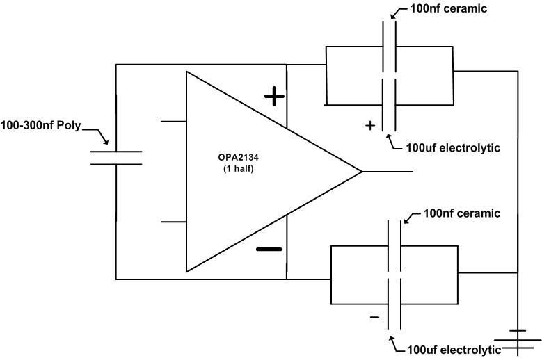
Although the OPA 2134 is a 'dual', the pair of op amps within the single DIL package share common +v and -v pins (pins 8 & 4), so your schematic applies for the pair rather then for each individual op amp.
Otherwise your schematic is how I interpreted the thread. I've now got the caps and will crank up the iron over christmas........sure is gonna get crowded under the board!! I note that somewhere in one of these posts it is suggested that they be soldered directly on the pins, but I figure this is too messy and probably not neccessary and soldering onto the pins of the DIL sockets under the board would be OK. Perhaps Carlos could confirm this and the schematic.
Otherwise your schematic is how I interpreted the thread. I've now got the caps and will crank up the iron over christmas........sure is gonna get crowded under the board!! I note that somewhere in one of these posts it is suggested that they be soldered directly on the pins, but I figure this is too messy and probably not neccessary and soldering onto the pins of the DIL sockets under the board would be OK. Perhaps Carlos could confirm this and the schematic.
Hi,
the small HF caps should be soldered in with the shortest possible route between cap and opamp. This means trimming the cap leads short and soldering them direct to the same pads as the opamp, preferably without a socket.
The electrolytics are less critical and may be soldered in upto 10mm away from the opamp pins. Well, you might get away with 20mm if space is a problem.
carlosfm,
Fascinating stuff!
- any preference on electrolytic type? (standard, low-ESR, tantalum, solid-polymer, MLCC?)
- have been experimenting with large-value MLCC X7R types for both audio-coupling and power decoupling, posting results in a few weeks...
Fascinating stuff!
- any preference on electrolytic type? (standard, low-ESR, tantalum, solid-polymer, MLCC?)
- have been experimenting with large-value MLCC X7R types for both audio-coupling and power decoupling, posting results in a few weeks...
Stuey said:Carlos doesn't post on this forum anymore.
That's a pity, I always enjoyed his posts. Do you know where he does post?
Thanks,
Simon
Sorry for necroing a very old thread, but this is some really good information.
Has anyone tried similar techniques (i.e. bypass from V+ and V- to GND with 47uF electrolytes and V+ to V- with 100nF Polypropylenes) on other OPAMPs? I want to try this mod on an NJM4580 but I'm not sure whether it's a good idea.
Has anyone tried similar techniques (i.e. bypass from V+ and V- to GND with 47uF electrolytes and V+ to V- with 100nF Polypropylenes) on other OPAMPs? I want to try this mod on an NJM4580 but I'm not sure whether it's a good idea.
Sorry for necroing a very old thread, but this is some really good information.
Has anyone tried similar techniques (i.e. bypass from V+ and V- to GND with 47uF electrolytes and V+ to V- with 100nF Polypropylenes) on other OPAMPs? I want to try this mod on an NJM4580 but I'm not sure whether it's a good idea.
It is always good to bypass power supply to GND, no matter which opamp is in question.
I'm using regularely 4,7uF - 10uF SMD tantals, which are even better (and equivalent t around 1: 10 to electrolytics)
Hmm, since I don't know where else to post I'll post this here anyway. What is the difference between the OPA2132 and OPA2134? I could only order the OPA2132 from ti.
Pierre
Pierre
Last edited:
I'm pretty sure the 2134 is just a de-rated version of the 2132. They probably start out on the very same production line and then are tested, sorted, and stamped.
- Status
- Not open for further replies.
- Home
- Amplifiers
- Chip Amps
- OPA2132 bypass