I made them.
I made them of course. I can't even buy decent ready made cored toroids for class D let alone something as radical as those.
.Thanks for the update sendler. Maybe I missed a post earlier but are these self-wound or did you buy them?
I made them of course. I can't even buy decent ready made cored toroids for class D let alone something as radical as those.
Air core toroid constuction
It wasn't too hard. A little time consuming but not any more so than winding a magnetic core. I started with 60 turns on a 1/2 inch wood dowel. Slide the cylindrical coil off the dowel and shape it into a toroid by spreading the coils on one side to become the outside of the toroid. Small tie straps hold the ends together and then some spray automotive clear to give it some strength. I am going to try some 14guage litz wire with a special low profile cable tie (7483K35) inside the toroid to compress the inner diameter a little, and one more tie around the outside before the clear to make it solid enough to reduce magneto-striction and microphonics.
.
McMaster-Carr
.
Use the calculator to get your value in the ball park. Compute the value for a certain number of turns at the outer length (circumference) and the same turns for the inner length and your value should be 1/2 way between those.
.
Coil Calculator - Single-layer and mutil-layer coil calculation in javascript
.
If you want more inductance, you can increase the dowel size to 3/4" and make it to a final value toroid of 10uH with 62 turns. A 1 inch dowel will get you all the way up towards 18uH with the same outer diameter that I have.
The toroids do exhibit much better EMI containment although not quite as good as the T106-2 cores which also leak a little more noise than the original little shielded bobbins.
How did you determine this?
Sniff the noise with an AM radio
Tune an AM radio between stations to the switching frequency around 650kHz. Then, turn the amp on and off while listening to the change in the noise of the radio.
.How did you determine this?
Tune an AM radio between stations to the switching frequency around 650kHz. Then, turn the amp on and off while listening to the change in the noise of the radio.
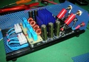
and they are monstrous !!! 😱 HUGE.. 😎The new 14ga. air core toroids are playing and they
here's mine, much more standard ArjenHelder inductors,
born yesterday..
 0113 - Servimg.com - Free image hosting service
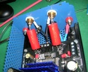 0212 - Servimg.com - Free image hosting service
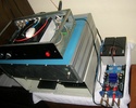 0312 - Servimg.com - Free image hosting service
An externally hosted image should be here but it was not working when we last tested it.
[img=http://img23.imageshack.us/img23/6813/00sotto.th.jpg]
An externally hosted image should be here but it was not working when we last tested it.
[img=http://img23.imageshack.us/img23/2599/03fianco.th.jpg]
Last edited:
here's mine, much more standard ArjenHelder inductors,
born yesterday..
Very nice. Finally someone sporting a Zalman.
What filter caps do you use for the output?
Tiny bit of help please. 🙂
I have the 4 channel sure board and the meanwell 27V supply. I am fitting it all together. I will be using this amp for my computer monitors.
Output is from my sound card. I want to put volume controls in and have no idea what value to use. I know I need log taper but do I use 10K or 50K or some other value.
Any help would be appreciated. Thanks in advance.
Terry
Tiny bit of help please. 🙂
I have the 4 channel sure board and the meanwell 27V supply. I am fitting it all together. I will be using this amp for my computer monitors.
Output is from my sound card. I want to put volume controls in and have no idea what value to use. I know I need log taper but do I use 10K or 50K or some other value.
Any help would be appreciated. Thanks in advance.
Terry
The manual for my 2 channel unit suggests the value of 50K and that's what I have used on my board. I am happy with it. I mean it's dead quiet when I turn the knob to the leftmost, and I never have to turn it to the rightmost as it gets too loud for me. And on my board, there is a DIP switch that can be used to set the gain of the amp, but then I have never set them to anything other than in all off position. BTW, mine is a 2 channel version, not a 4 channel version.
I remember reading somewhere that the potentiometer value should match the input impedence of whatever it will be controlling, but sorry to say that I can't remember where I read it from.
thank you 🙂Very nice. Finally someone sporting a Zalman.
What filter caps do you use for the output?
Zalman's suitable ones
(northbridge coolers ZM-NB32K ::: Zalman, leading the world of Quiet Computing Solutions ::: and ZM-NB47J ::: Zalman, leading the world of Quiet Computing Solutions :::) are twice and 3 times the weight oh original heatsink,
but Zalmans are 37x37 mm. of base,
unfortunnately non completely covering the two TP2050 chips
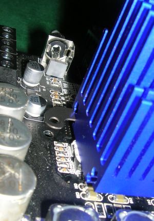
but i don't think this uncovered 1.5mm. (both the sides) will cause heating problems..
03_dis10 - Servimg.com - Free image hosting service
06_2di10 - Servimg.com - Free image hosting service
in the next days, i'll be able to provide ZM-NB32K photos, i have to move to it because ZM-NB47J is 2mm. higher than my maximum permitted..🙁
forgot this part..What filter caps do you use for the output?
well, i used 10mH - 470nF - 100nF , as stated in the Notes of TK2050 DS (and formerly "ok tested" by other users of T-Forum)
Inductors from ArjenHelder, Caps are Epcos MKP from RS.
i didn't mount Zobel network, because i'm not sure on electrical parameters of my speakers, so i can't calculate right values for Cz and Rz..
Fanless will sound better
.
Newegg.com - ZALMAN ZM – 32K Heatsinks only - Memory & Chipset Cooling
.
I think the original little fanless heatsinks would have worked fine if Sure had used some Arctic Alumina to glue them on with rather than the rubbery stuff that was there. The chips were sometimes getting much hotter than the sinks. Though you would never get the epoxy off again if the chips needed a repair. Your spring clips will be nicer for that reason. As long as I had the heatsink off, I might also try tinning the legs of the output chips with some solder to increase the effective guage. They are very light guage for a power chip.
I will go back to fanless as well. Newegg has the smaller heatsinks for only $4.00 in the USA which will be cheaper than adding the additional power supply I am using to isolate the fan noise from the 5v supply.in the next days, i'll be able to provide ZM-NB32K photos, i have to move to it because ZM-NB47J is 2mm. higher than my maximum permitted(
.
Newegg.com - ZALMAN ZM – 32K Heatsinks only - Memory & Chipset Cooling
.
I think the original little fanless heatsinks would have worked fine if Sure had used some Arctic Alumina to glue them on with rather than the rubbery stuff that was there. The chips were sometimes getting much hotter than the sinks. Though you would never get the epoxy off again if the chips needed a repair. Your spring clips will be nicer for that reason. As long as I had the heatsink off, I might also try tinning the legs of the output chips with some solder to increase the effective guage. They are very light guage for a power chip.
yes, you're right..I think the original little fanless heatsinks would have worked fine if Sure had used some Arctic Alumina to glue them on with rather than the rubbery stuff that was there
i didn't try by myself, but many T-Forum users (don't know if also some diyAudio user) have cleaned everything from this stupid rubbery and remounted the original heatsink with the proper thermal grease, and experienced strong enhancements on heat dissipation, so they won't upgrade their heatsinks, because they remain quite warm..
madqwerty, what method are you using to charge those in-series batteries? How are you liking the sound, btw?
our little forum, T-Class focused but rapidly growing on diy-side.
Where is the T-Forum? Link?

unfortunnatelly for you, it's in italian (but many of us can write in english, if you've to ask something)
main page Forum gratis : T-Forum :: T-Class, HiFi revolution
SureTK related threads :
- nuova scheda sure (first introductive thread )
- Sure electronics TK2050 le MODIFICHE (more tweaking & diy focused)
and much other things..enjoy ! 🙂
hi,madqwerty, what method are you using to charge those in-series batteries? How are you liking the sound, btw?
i'm using a Regulated Power Supply, with V ranging 0-100Vdc , and I ranging from 0 to 900mA, both configurable.
I like the theory who wants Pb Gel / SLA batteries to be charged like NiMh, so
Max V = Nominal V * 1.15
Max I = C / 10
so, for a single 12V/7Ah battery, i use Vmax=13.8V and Imax=0,7A.
Due to the high voltage limit of my supply, i can recharge more batteries connected in series, with the same rule : Vmax = 13,8 x Nun. of batteries connected, and Imax = 0,7A..
Don't know if it's a good method, my SLA batteries seem to like it 🙂
sounding : unfortunnately, i didn't have extended tests with smps because of its noisy and annoying fan, i use batteries because i have them, and i sold the noisy smps...i can report a slight sensation of more clean , "stable" and focused sound, but i made fast comparations only on the "factory default" SureTK, months ago..sorry! 😉
Last edited:
Those are solid calculations for recharging, I think. I'm also using a 7Ah battery and will pick up another one soon to put in series. I'm still waiting for my Sure board--almost two weeks now.
- Status
- Not open for further replies.
- Home
- Amplifiers
- Class D
- Sure Electronics New Tripath Board tc2000+tp2050