The responses are quite different. I think, it is difficult to place a small speaker on a large panel but not impossible. Polar response and bass limit are two opposite parameters to optimize for the designer.
🙂
I think you nailed it perfectly. It is a compromise between baffle size, low-end frequency extension, and smooth response. There is no free lunch 😎
completeness & accuracy of simulations
"I don't trust simulation. They are accurate up to certain extent only"
That would depend entirely on the completeness & accuracy of the logic in the simulation.
I'd guess that just about all of us here would trust TS simulation of bass response.
maybe because off axis response is rarely simulated, we have difficulty trusting it.
It’d be inaccurate to the extent it ignores variables, eg the shaping or curvature of the cone differing from a conventional profile. But on this factor, I suspect there's not much variation. I might be wrong, maybe "we dont know, what we dont know"
I think off axis response is a significantly under valued area. If modelling is accurate, it saves a lot of experimenting and lack of optimal results
Martin,
How complex is your simulation model of off-axis response, compared to our familiar TS simulation of bass response?
Can you comment on (or link to previous comments on) attempts to verify the modeled predictions of off-axis response, with then building and measuring?
Do your models predict open baffle line arrays inc off-axis response, as well as they do conventional arrangements?
Cheers
Last edited:
rule of thumb: baffle width <= 2x driver diameter is not meaningful
'baffle width <= 2x driver diameter' should not be taken as a rule. It is the consequence of two goals:this I can understand.
Can anyone make the case for narrow open baffles as clear and meaningfull as MJK.
1. to limit a drivers frequency response to just above the first dipole peak of the baffle it is mounted on.
2. to let the driver become directional at the same region where it is rolled off.
You will find the theory about it at Kreskovsky. Linkwitz' Orion and Kreskovskys Nao are follwing these goals - at least for the midrange.
Why should one have those goals?
Lets look to measurements of an OB following them:
This is the front and back view of a 3'' fullrange driver on a narrow baffle. The driver is mounted as is to get the rear response as similar to the front response as possible.
An externally hosted image should be here but it was not working when we last tested it.
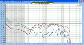
These are measurements for the front (left) and back (right) radiation:
An externally hosted image should be here but it was not working when we last tested it.
They are nearfield (about 30 cm from the voicecoil) to exclude reflections (the measuring software does not allow for gating). This leads to the 60deg front radiation being somewhat shadowed from the microphone.
You may see that the response is pretty well CD up to the dipole peak. CD will detoriate above the peak. A tweeter should come in above 2 kHz.
You will also notice that the response falls immediately below the peak, putting high demands on the drivers excursion capabilities. As jerome69 already said:
Polar response and bass limit are two opposite parameters to optimize for the designer.
How complex is your simulation model of off-axis response, compared to our familiar TS simulation of bass response?
The drivers are represented by the T/S parameters so they behave as perfect single degree of freedom but directional piston sources. The driver modeling does not include cone break-up, my version of the models can include an adjustment to reduce the output from the rear of the cone although I have not used that feature in any design. The models are set up to analyze one or two woofers crossing over to a midrange or full range driver.
The baffle geometry and the placement of the driver on the baffle is included. Passive or active crossovers can be modeled and the driver impedance is included in the passive crossover response. The floor, ceiling, rear wall, and side wall can be included and the OB can be rotated to an angle relative to the rear wall. In my personal version, all the boundaries of a rectangular room are included but this has not been released for a number of reasons including longer running times. Room boundaries include a frequency dependent absorption coefficient. You can calculate response at any location relative to the OB system or at a set listening position in the room while you move the OB speaker relative to the corner.
Can you comment on (or link to previous comments on) attempts to verify the modeled predictions of off-axis response, with then building and measuring?
The best data I have comparing calculated to measured is in my documentation of the passive crossover configuration for my Jordan JX92S OB and Goldwood H frame project. I do not have methodical on and off axis measurements outdoors. But the measurements in the write up show the response 1 m on-axis and at the listening position off-axis. My take on these correlations is that the model is accurate with the exception of driver response anomolies which are in no way a function of an OB design. Once you look at the magnitudes of the peaks and dips produced by the driver and the room you need to ask yourself if you are still really concerned about small wiggles brought about by operating an OB system above the dipole hump. I am not concerned and conclude that these small anomolies are in the noise if you have designed the driver locations and crossover points correctly.
If you now believe the models, as I do, then the sudy I mentioned in my original post is valid. If you have the models you can recreate this study and draw your own conclusions.
Do your models predict open baffle line arrays inc off-axis response, as well as they do conventional arrangements?
No, I have nothing that will simulate that configuration at this time. It could be modeled but it is not on my list.
if the OP intend to listen to his speakers on axis, in the sweet spot only then the baffle size will be a moot point for him.
Rudolf re post 43
You posted those 2 pics before, but (no matter how long i look at them) I'm not certain what each demonstrates. The right one is from the back, a 3'' fullrange driver; on a baffle how wide? (and the left one?)
Your aim is get the rear response as similar to the front response as possible. Is this
- To coincide with the XO’s frequency to the tweeter?
- with a view to doing anything in particular above the dipole peak, eg, is your tweeter dipole or monopole?
If you want to cross to the tweeter at frequency X, is their a formula that you think suggests optimal baffle width?
Thank you
'baffle width <= 2x driver diameter' should not be taken as a rule. It is the consequence of two goals:
1. to limit a drivers frequency response to just above the first dipole peak of the baffle it is mounted on.
2. to let the driver become directional at the same region where it is rolled off.
You will find the theory about it at Kreskovsky. Linkwitz' Orion and Kreskovskys Nao are follwing these goals - at least for the midrange.
Why should one have those goals?
Lets look to measurements of an OB following them:
This is the front and back view of a 3'' fullrange driver on a narrow baffle. The driver is mounted as is to get the rear response as similar to the front response as possible.
An externally hosted image should be here but it was not working when we last tested it.
These are measurements for the front (left) and back (right) radiation:
An externally hosted image should be here but it was not working when we last tested it.
They are nearfield (about 30 cm from the voicecoil) to exclude reflections (the measuring software does not allow for gating). This leads to the 60deg front radiation being somewhat shadowed from the microphone.
You may see that the response is pretty well CD up to the dipole peak. CD will detoriate above the peak. A tweeter should come in above 2 kHz.
You will also notice that the response falls immediately below the peak, putting high demands on the drivers excursion capabilities. As jerome69 already said:
So lets go the next step and take this idea to a full system design using the driver shown in the plots.
We want to use the linear response below the baffle hump, this extends from approximately 200 to 2 kHz with the SPL falling about 20 dB from the highest frequency to lowest frequency in the range. We will need to add another driver to cover the frequencies below 200 Hz, that is easy. Then we will need to add one and possibly two more drivers on different narrow baffles to extend the response from 2 kHz to 20 kHz, the baffles start to become very narrow and tweeters might not be operating as a dipole.
Assuming we have all the drivers and the correct baffle widths we have a three or four way system with each driver providing a linear rising SPL response that can vary as much as 20 dB over the frequency range. Now we need an amp, crossovers, and some EQ for each driver so that each driver produces a uniform SPL response over its intended operating frequency range. Since the narrow baffle is rolling off the response of each driver with decreasing frequency, the SPL/W/m values on the spec sheets are out the window and we need to push more power at the lower frequencies to bring the SPL back up and in line.
Does this sound complicated to anybody but me? And lets say we are able to solve this design task, we will have a system that is very linear and operating as a dipole at a measurement distance of 30 cm. Do people listen to OB systems at 30 cm?
Can I design a two way OB that meets these design goals? No.
Can I do this with passive filters? No.
Can I use a single amp? No.
Does SL Orion speaker sound great? I am sure it does.
Does John K's NAO speaker sound great? I am sure it does.
Does gainphile's and Rudolf's speaker systems sound great? I am sure they do.
Personally, I am not smart enough to take on the challenge of desiging narrow baffle OB speakers (or maybe I am too smart to take on the challenge).
Once we get out into the room, I believe that other influences are going to drown out all of our work to get a smooth perfect dipole response. The complexity of the design, the cost, the filters and EQ, the power applied to the drivers just do not seem reasonable to me and that is why I am not a believer in the "cult of the narrow baffle".
I am not trying to rain on anybody's parade and I hope my comments are taken with a wink and a smile, but it just seems too complex and expensive if done correctly to make any sense and I am not convinced there is a clear advantage. If somebody has designed such a system I tip my hat to them. I like simple and elegant solutions over brute force solutions.
You posted those 2 pics before, but (no matter how long i look at them) I'm not certain what each demonstrates. The right one is from the back, a 3'' fullrange driver; on a baffle how wide? (and the left one?)
It is the same driver (Visaton FRS 8) on the same triangular baffle. At the center of the driver the baffle is 11,5 cm wide. The driver cone is 6,5 cm wide. The front cut-out is tapered 45 deg.
Not with the XO frequency, but to get the front and back XO region as similar as possible. I have shown elsewhere, how front and back radiation can differ with a conventional approach.Your aim is get the rear response as similar to the front response as possible. Is this
- To coincide with the XO’s frequency to the tweeter?
This all would be moot, if the tweeter wasn't dipole and you wouldn't try to push its dipole peak as high as possible..- with a view to doing anything in particular above the dipole peak, eg, is your tweeter dipole or monopole?
You have to look for the effective baffle width, not the geometric. Take EDGE and find a baffle geometry that delivers the first dipole peak where you want it. You have to put the driver equidistant to the left and right baffle sides.If you want to cross to the tweeter at frequency X, is their a formula that you think suggests optimal baffle width?
if the OP intend to listen to his speakers on axis, in the sweet spot only then the baffle size will be a moot point for him.
I disagree with this - our brain integrate the rooms reflections for a substantial period of time, and accumulate reflections both on and off axis (see Toole's recent book for reference). Any spectral differences of off axis radiation from the speaker lead to timbrel coloration. For OB systems, this is particularly true between 1500 - 8000Hz, depending on the baffle and driver.
Martin,
you are spot on with most of your remarks - as was to be expected 🙂 :
While below say 300 Hz the room (modes) will have a dominant influence on what we hear at the listening position, I would like to differentiate above that.
With this in mind I don't see any rivalry between your approach and mine - narrow baffles are just the icing on the cake 😛
Best regards
Rudolf
you are spot on with most of your remarks - as was to be expected 🙂 :
- For a 'perfect' narrow baffle system you would need 4 ways, three ways already is a compromise.
- Passive filters are possible, but I needed 8 filter components for the woofer-mid XO and EQ alone, and probably as much for the mid-tweeter XO/EQ, which I did not build in the end, because ...
- active filters with multiamping are mandatory if you want any real freedom in the choice of the drivers. I use a Behringer DCX 2496 in conjunction with an Onkyo 7-channel AV-receiver. This keeps complexity to a bearable level (for me).
While below say 300 Hz the room (modes) will have a dominant influence on what we hear at the listening position, I would like to differentiate above that.
- We have the direct (on axis) response (including floor reflection perhaps), which obviously can be controlled regardless of a specific baffle width.
- We have the (late) front wall reflections, which our mind can separate from the direct response pretty well. I like those reflections to resemble the direct response a bit. That's why I recommend rear tweeters.
- We have the (early) side wall reflections, which our mind will separate from the direct sound, if both are different enough in their spectrum. I am fully aware that the dipole radiation pattern in itself helps to avoid a lot of side wall reflections, but I find that narrow baffles do two things above that:
- They keep the dipole eight from blooming and
- they make the remaining side wall reflections have the same spectrum as the direct waves. This helps to hide them from our hearing.
With this in mind I don't see any rivalry between your approach and mine - narrow baffles are just the icing on the cake 😛
Best regards
Rudolf
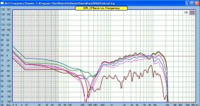
Here is a set of on and off axis measurements of a Neo3 tweeter, one on a 28cm baffle, one with no baffle. Compare the regions between 1-10kHz. The first one is 0-45-60-90deg with baffle (ignore below 1k), the second is 0-15-30-45-60-90deg without baffle. Can you see how irregular the first is off axis? For the second measurement, you can see how the region of irregularity is much narrower, centered around 8k.
PS - Ditto Rudolf - particularly the bit about how much we've learned from Martin!
PS - Ditto Rudolf - particularly the bit about how much we've learned from Martin!
Attachments
Last edited:
Oh, and sorry to the OP for going a bit off topic - please keep us updated, maybe post some pictures. I think some measurements and listening is in store to get a better answer to your original question. Something you might try is listening 'loud' - particularly with more complex music, this tends to show up speaker deficiencies. Or with vocals, a mid-driver in your situation may become unpleasant sounding at louder levels. That will let you know the driver is running out of linear excursion.
Since all of you have more experience than I do with open baffle, might I request a critique, before committing to build?
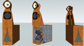
Tri amped, using a DCX Berringer with stepped transformer attenuators for the six channels and a stepped input, so I can run the thing at full bit rate. The damping is chopped jeans cotton wall insulation and the bass cabinet is from John K's cardioid bass section. Other drivers are Lowther PM6A 18 ohm, suitably re tuned, an Emminenece Delta 8 16 ohm from 300 Hz to 80 Hz, eq'd flat and Tang Band long excursion woofers.
Any comments would be appreciated.
Bud
Attachments
Perhaps this warrants another thread?
It looks pretty, but also expensive. I would invest in modeling and measuring, but that's just me.
I doubt the Delatlite, used as a mid, can reach that low. Even the best 8" drivers can only go down to 125Hz or so. Your highs are going to suffer by using a large wizzer cone driver - no dipole action, fairly uneven FR, and will beam. The woofers are 8" also? If so, they look low sensitivity and will have limited output and limited low end - there is better for the money. Designing a cardioid woofer is not easy, esp. with special damping material. I would never be able to get that right without a lot of measurement - hence my never trying a cardioid woofer. And IME, its the mid that suffers the most from backwave interactions, not the woofer.
Just my first take - we may prioritize things differently though. I'm into strong basic engineering first, then tweaking. YMMV.
Perhaps this warrants another thread?
Ok, thank you for your comments cuibono. I will provide more information on the new thread.
Bud
since this is a tweeter, then can I assume that 3k to 30kHz is a sensible frequency range and since it is a dipole then it is a worst case example?on and off axis measurements of a Neo3 tweeter, one on a 28cm baffle, one with no baffle.
If so then the baffled version seems to have similar severe/moderate irregularities cf the unbaffled version.
If we were listening to a sealed back dome tweeter fitted to a zero baffle or a big baffle (>=2times the dome diameter) what difference on axis could we expect to hear?
Would a big baffle benefit from measures to ameliorate the edge diffraction for a dome?
Is the baffle that is normally fitted to all dome tweeters, say 110mm diameter relative to a 25mm diameter dome, guaranteed to prevent us ever using it baffleless (or should that be without baffle)?
I want to really thank you guys for your work and clear postings.
The potential value and challenges of narrower baffles up high is clear. Looking into an active with eg a Behringer DCX 2496.
If 3 inch drivers are used on a baffle of the minimum width that could be used for sufficient strength, say 100 mm: The 1st dipole peak per Kreskovsky http://www.musicanddesign.com/Dipoles_and_open_baffles.html would be
dipole peak = Fp = C/ 2d.
Pardon my ignorance, but with baffle of 100 mm, is d = a simple 100 mm?
or to be precise:
• On the front, the distance from the centre of the driver’s dust cap, to the side. This would be longer than 50 mm, due to the "recessing in" of the cone. Plus
• The baffle's thickness, eg maybe 12/ 19/ 25 mm. Plus
• On the back, the distance from the side to the centre of the driver’s cone.
As an example, for a 3 inch driver on a baffle 100 mm wide & 19 mm thick, this could be:
say 60 + 19 + 60 mm = 139 mm.
Ie about 40% more than the simple baffle width suggests.
Am I right? or is "D" simply the added distance the rear wave must travel to your ears, compared to the front wave.
which in my example would be 19 + 60 mm = 79 mm?
and what is C?
Last edited:
C is the speed of sound, approx. 344 m/secIf 3 inch drivers are used on a baffle of the minimum width that could be used for sufficient strength, say 100 mm: The 1st dipole peak per Kreskovsky http://www.musicanddesign.com/Dipoles_and_open_baffles.html would be
dipole peak = Fp = C/ 2d.
d is the dipole distance. This is NOT the distance from the driver to the baffle edge, but
the difference (b-a) between the distance
a - which the sound has to travel from the front radiation origin to the ear (or microphone) and
b - which the sound has to travel from the rear radiation origin to the ear.
b will not be a fixed value because the sound has to creep around all edges of the baffle, which will not be all equidistant from the radiation origin (except for a driver centered on a circular baffle). So the most precise (and most comfortable) way will be to use EDGE or one of the other OB simulation programs and let the program do the integrating and calculating.
EDGE will assume that the front and rear radiation origins have the same distance from the ear. EDGE does not account for longer travel caused by baffle depth, frames, wings etc. You will have to add that by yourself. Other OB simulation programs will account for some or all of the above.
Rudolf
In this case it is almost the same as for a boxed speaker with the same baffle size.If we were listening to a sealed back dome tweeter fitted to a zero baffle or a big baffle (>=2times the dome diameter) what difference on axis could we expect to hear?
In the same way as a small baffle would.Would a big baffle benefit from measures to ameliorate the edge diffraction for a dome?
Thanks Rudolf
I’ve done a first cut of the 1st dipole peak. Can you confirm the calculation’s order of magnitude?
Trying to push the 1st dipole peak as high as possible with a baffle of the minimum width, d averages (b not being a fixed value) say 88 mm
Does the 1st dipole peak = 344 * 1000/ 88 = 3909 Hz sound approx right?
(I do realize that I'll lose the low end on this skinny baffle! but the driver below this is capable of going quite high, cleanly and flat)
Last edited:
- Status
- Not open for further replies.
- Home
- Loudspeakers
- Multi-Way
- HELP: xmax and open baffles