How thick area is neded?No, those won't work you need inductance in the order of 2-10mH,
also they need to be able to handle the current and have a low resistance.
http://www.hifikit.se/show_kat.asp?KatName=SPOLAR&KatID=666
Those biggies is a little expensive..
I don't know if those speaker induction coils can handle the current without saturating.
Also in the specs of those coils you don't find anything about DC current, they're made for speakers and that's AC (otherwise you have a problem 🙂)
If such a coil saturates then it behaves the same as a resistor but a very expensive one!
You're better off with finding a manufacturer who makes chokes to you specs: cheaper and better.
Last edited:
OK, need to think more about that. Would it be that hard to make one of your own I wonder? If you had some large section enamelled wire maybe?
Fran
Fran
Here are some CLC models.
The models are made with the same total capacitance and the same total inductance.
The results clearly show that CLCLCLC easily beats CCLCC. I suppose this is to be expected but it is nice to see the difference visually.
The cost to build the two different versions is the same since total capacitance and total inductance is the same for both versions.
Attachments
Last edited:
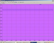
Here is a jpeg of the results.
The blue trace is CCLCC.
The green trace is CLCLCLC.
The blue trace is CCLCC.
The green trace is CLCLCLC.
Attachments
Last edited:
Speaker crossover inductors come in air core or iron core. An air core inductor will not saturate.
There are lots of aircore inductor calculators on line. I just did a fast calculation.
For a DIY 5mh air core coil 1.24 lbs of #16 magnet wire on a 1 inch diamiter 1 inch long
form will be ~2.75" in diameter and have a dc resistance of .65ohms . As I said this was a fast calculation you can play with the coil diamiter and legnth and find an optium coil
legnth and diamiter.
It looks like a fun little thingie, but the 0.5Vrms output doesn't sound like enough for the F5 IMHO.
I'm not sure, but I think the flat inputs send the input signal through the attenuator and filters direct to the output.
Feed in 300mV and get 300mV out.
Feed in a peak of 5Vrms and get a peak of 5Vrms out. That seems to be what the manual is suggesting.
This will work well with all modern sources and the Tape section tells you how to modify the sensitivities for other less usual sources.
Last edited:
Would you think the IRFP 540 and 9540 make acceptable substitutes for the output devices of the F5? Any candidates for the input pair if no SK/SJ available at all? I'm keen to see the differences from changing out the parts to something locally available for my second build (woofers).
On another note, I got the heatsinks, I hope there will be no problems with these ones - I should post photos in a few days. They have 1/2 inch thick bases and are 12x15x8", two should be enough for a stereo F5 hopefully - they weigh about 10lbs each though they don't have as much surface area as I would like. The problem is that the local shops have no Rth charts, so I won't know till I fire them up... they cost me about 70 dollars which seems steep, but they should be good this time.
On another note, I got the heatsinks, I hope there will be no problems with these ones - I should post photos in a few days. They have 1/2 inch thick bases and are 12x15x8", two should be enough for a stereo F5 hopefully - they weigh about 10lbs each though they don't have as much surface area as I would like. The problem is that the local shops have no Rth charts, so I won't know till I fire them up... they cost me about 70 dollars which seems steep, but they should be good this time.
OK, need to think more about that. Would it be that hard to make one of your own I wonder? If you had some large section enamelled wire maybe?
Fran
Do it all the time for DIY switch-mode power supplies -- I get my inductor cores from Amidon -- I also used Amidon cores for baluns -- they have a lot of information on which cores to use on their website -- ferrites for some, iron cores for others.
https://www.amidoncorp.com/
Would you think the IRFP 540 and 9540 make acceptable substitutes for the output devices of the F5? Any candidates for the input pair if no SK/SJ available at all? I'm keen to see the differences from changing out the parts to something locally available for my second build (woofers).
On another note, I got the heatsinks, I hope there will be no problems with these ones - I should post photos in a few days. They have 1/2 inch thick bases and are 12x15x8", two should be enough for a stereo F5 hopefully - they weigh about 10lbs each
If you have a thermometer, a power resistor and a power supply you can measure their thermal impedance. Attach the power resistor to the heatsink, measure the ambient temperature, cook the resistor at a measured number of watts for 10 minutes or so (i.e. if it's a 50W, 100 ohm resistor, use your Ohms law to figure the required voltage), measure the temperature at the end. The temperature delta divided by the power gives you a pretty good approximation of the statistic sought. I use this method with all the dumpster heatsinks I've come across.
FWIW, the Yamaha A-10 integrate amp I modded used a heatsink made of aluminum flashing folded accordian style -- and it runs really well. The thermal impedance is Mostly (not entirely) related to surface area.
I am trying out the TO-220 Fairchild Semiconductor devices to replace the TO-247's.
CLC is always better than CRC
CLC is 3 poles.
Model 2 pole filters for equivalency.
Thanks again Jack. I have some 10 ohm, 50 watt resistors and a thermal attachment for my multimeter, so maybe I'll do just that.
These heatsinks are meant for power rectifiers and I was told that 60 watts/20 degree rise would be a piece of cake for them, so I'm hoping for the best. They have a very thick and heavy base with two thick semi-circular ribs that extend from it, and the fins are then extruded from the ribs. It seems not as much surface area as a regular flatback heatsink, but much more mass.
It seems a lot of receivers come with the accordion-style heatsinks, my Pioneer receiver has the same thing, but with some sort of base press-fitted on to the flashing 🙂
I'll look forward to your results using the TO-220s. The only thing of note between the 540/9540 and 240/9240 (the originally specified devices) is the slightly slower rise and fall times, and the 100V rating instead of 200V. It really freaked me out to see a shop attendant here who looked at the Fairchild part numbers, deduced their ratings from the part number itself, and suggested the replacements (shops here usually have very dumb attendants). I bought four devices for about $3, if not in the F5 they can surely be used somewhere else...
I'd also love to hear of suitable candidates for the input pair, in case someone happens to try something else out.
Jack,
Will the temperature delta (/Power) so measured be that of the total resistance from the resistor to ambient? It would include the thermal resistance of all the interfaces between the resistor and the ambient, and not just the heatsink to ambient.
Will the temperature delta (/Power) so measured be that of the total resistance from the resistor to ambient? It would include the thermal resistance of all the interfaces between the resistor and the ambient, and not just the heatsink to ambient.
I'm assuming it will also include the internal thermal resistance of the resistor, which for a regular ceramic resistor will be pretty high. I plan to use a 30 watt soldering iron element. It will not be very precise, but it will tell me whether the heatsink will work or not...
Jack,
Will the temperature delta (/Power) so measured be that of the total resistance from the resistor to ambient? It would include the thermal resistance of all the interfaces between the resistor and the ambient, and not just the heatsink to ambient.
It's best to some silicone grease to the flat side of the resistor -- I use the finned Dale resistors for this -- so they are conducting to the heat sink and radiating into free air. The transistor will radiate as well (so do your IC's and voltage regulators) so you could use a 240/9240 as well and measuring the idle current and Vds etc. to arrive at the effective thermal impedance.
CLC is 3 poles.
Model 2 pole filters for equivalency.
funny - L input filter is even better , sound wise
You can actually determine it using heat transfer equations for finned heatsinks. Don't even need to measure it. But then you need a lil' engineering background.
Lemme see if I can dig this up.
Lemme see if I can dig this up.
Thanks, ra7. It would help me skip a step.
It's a 'pi' shaped sink with the devices mounting to the flat side and fins along the two 'legs'. I searched for a similar profile through the Aavid site but could not find something to approximate the thermal performance.
It's a 'pi' shaped sink with the devices mounting to the flat side and fins along the two 'legs'. I searched for a similar profile through the Aavid site but could not find something to approximate the thermal performance.
block bridge vs MUR
has anyone compared bridge block vs MUR30x0
I use bridge block (KBPC3510) at now but got low rails - 21.8Vdc
I wonder how on semi ultrafast and softrecovery devices would perform
Is there something special about bridge mr Pass use In his F amps
has anyone compared bridge block vs MUR30x0
I use bridge block (KBPC3510) at now but got low rails - 21.8Vdc
I wonder how on semi ultrafast and softrecovery devices would perform
Is there something special about bridge mr Pass use In his F amps
- Home
- Amplifiers
- Pass Labs
- F5 power amplifier