Hello
Bias current can not tell us if one audio amplifier works in class A or AB or B. It is not enough just that. I think yours make some mistake here.
To answer this, I posted the following two image files. Class AB is Class B with a higher bias current. So all.
Topological, Class B differs from Class A, as shown in pictures.
Best Regards
You can have class A also with first topology.
class A mearly means that the amplifier conducts for a full cycle of an input sinusoide with only one device or set of devices in parallel. Therfore a heavily biased class AB is operating in class A upto a (depending on how overbiased) respectably high output level. Infact some class AB amplifiers are so overbiased the pchannel devices could just be replaced with a current sink!
donpetru,
How do we know for sure?
But wherein conditions? In fact, these conditions lead to not use diagram class AB and B in class A, in high power audio amplifiers. Diagram class AB and B it can only work that only low power audio amplifiers which runs on large loads (at least 32 ohms).You can have class A also with first topology.
bias current tells us all.
If we know the maximum output voltage and we know the ClassA resistance lower limit, then we know the maximum current that the load resistance will draw.
If all the output devices continue to actively supply that output current then the amplifier remains in ClassA.
The overriding requirement to achieve ClassA into a particular load resistance is the stage bias current.
If we were discussing single ended then Iout<Ibias. But we are not looking at single ended.
For push pull circuits Iout<2times Ibias.
There is some leeway in how much less than Ibias we need to be to maintain good linearity in the output. Too near the transistor Ic vs Vbe knee and linearity collapses.
Should that leeway (2*Ibias -Iout) be 1mA or 5mA or 50mA? Or does it depend on the topology adopted?
Suppose the following scenario, as we showed in the picture attached below. I think you refer to this scenario.
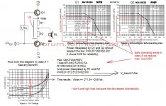
In the push-pull output stage, each transistor working in class A, when each emiter transistor is half of Ub. This means that the voltage on R1 and R2 is even Ub.
To find the resistance values need to know the characteristic of output transistors Q1 and Q2. For example, if Q1=MJ15024, Q2=Mj15025; we have: V_bias=~2,6Vdc (theoretical).
Power dissipation should not exceed one fourth of that specified in the catalog for safety. The power of the emitter resistances are high. Many disadvantages and after one question: whether the diagram operates in class A? Apparently yes, but ... will let yours find the answer.
Best Regards
Attachments
Lumba Ogir, I guess you understand what I mean.
Correct my expression above: "It is recommended, diagram class AB and B can work in class A, only in low power audio amplifiers, which runs on large loads (at least 32 ohms)".
And once again, please excuse my english.
Nice day
Correct my expression above: "It is recommended, diagram class AB and B can work in class A, only in low power audio amplifiers, which runs on large loads (at least 32 ohms)".
And once again, please excuse my english.
Nice day
Hi,
is there a general consensus on a proven diyer class AB that sounds pretty good? if so, which design would that be? something that can drive 4 or 8ohm load without any issues.
I'm been considering saving up for a pair of Emotiva XPA-1 monoblocks
to drive my Magnepan 1.6's. $2K is a bit steep for me. I'm wondering if
there is a diyer AB design that is can come close to class A.
thx
I think the most overlooked difference between class A and AB might be:
A) The sum of sum of push and pull currents is rigidly held to a constant.
Most usually a constant voltage drop across two opposing sense resistors.
Quiescent current sum is the same as full signal.
AB) Sum of push and pull currents is deliberately not held too firmly constant.
Some non-linearity (square or log law?) introduced to the current crossing.
Quiescent current sum less than full signal.
Last edited:
I think the most overlooked difference between class A and AB might be:
A) The sum of sum of push and pull currents is rigidly held to a constant.
Most usually a constant voltage drop across two opposing sense resistors.
Quiescent current sum is the same as full signal.
AB) Sum of push and pull currents is deliberately not held too firmly constant.
Some non-linearity (square or log law?) introduced to the current crossing.
Quiescent current sum less than full signal.
But a class AB amp will run in class A with low output signal. OTOH, if you take a class A amplifier, and connect a much lower load than specified, it will go into class B at higher levels.
Example: an amp with 200mA bias current in the output stage can provide 400mA peak output current in class A. Why? Because at 400mA output, the 'other' device just starts to shut off (and class A means that neither device should cut off).
So, is this a class A or class AB amp? Depends. If you drive it to 10V peak output into 25 ohms, it remains in class A all the time. If you drive it to 20V peak in 25 ohms, it will go into class B above the 10V point.
If you drive it to 8V peak into 8 ohms it will be in class A up till peak output voltage of 3.2V and go into class B above that.
So ANY amplifier can work in class A or AB, it all depends on the bias current, the output level and the load impedance. It has nothing to do with the topology per se.
Jan Didden
Last edited:
You can (and probably should) have AB without either device
ever shutting completely off.
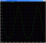
Or would you argue this (attached graph) is Class A behavior?
It looks like it is class A, but just at the limit, isn't it? The device is just at the limit of cut-off.
jd
Example: an amp with 200mA bias current in the output stage can provide 400mA peak output current in class A.
My point about Class A exactly..
Sum of push current, plus pull current, always equals a constant.
In your example: 200ma + 200ma = 400mA (same as full signal clip)
In Class AB amplifiers, the sum is NOT constant.
But a class AB amp will run in class A with low output signal. OTOH, if you take a class A amplifier, and connect a much lower load than specified, it will go into class B at higher levels.
Example: an amp with 200mA bias current in the output stage can provide 400mA peak output current in class A. Why? Because at 400mA output, the 'other' device just starts to shut off (and class A means that neither device should cut off).
So, is this a class A or class AB amp? Depends. If you drive it to 10V peak output into 25 ohms, it remains in class A all the time. If you drive it to 20V peak in 25 ohms, it will go into class B above the 10V point.
If you drive it to 8V peak into 8 ohms it will be in class A up till peak output voltage of 3.2V and go into class B above that.
So ANY amplifier can work in class A or AB, it all depends on the bias current, the output level and the load impedance. It has nothing to do with the topology per se.
Jan Didden
Exactly!
One could say that bias has to be half the peak current delivered to the load.
Just remember that you have to multiply or devide the DC values of current and voltage with the RMS factor sgrt 2 (1,41). 1V DC equals 1,41V AC, the same goes for the current.
The above numbers only goes for push pull amplifiers, single ended amplifiers has to have the bias set @ 100% peakcurrent delivered to the load to operate in class A.
Indeed. If you have a se amp with a standing current of say 1A, then that is the max output peak current at one polarity: the 'amplifier' device cannot take less than 0 A, it can only shut off, and that leaves the 1A of the current source or whatever biases the se stage as max Iout.
Now the se is a bit more interesting because on the one hand, the max Iout (in this example) is 1A if the 'amplifier' device cuts of, but the amplifier device itself can output much more than 1A in the opposite polarity, in theory only limited by its dissipation and power supply stiffness.
So a se amp has a non-symmetrical Iout: one side is the max of the bias (1A in this example) and the other polarity can easily provide several amps.
Where a pp class A amp will gracefully slide into class AB if it has to drive a lower load or at higher level than the design values, a se amp will then slide into not-so-gracefully asymetrical clipping.
jd
Hi
Janneman is of course right, no doubt about that.
Another issue is, why are some people so scared about an over biased class AB?
It seems to me that people has “studied” D Self and are scared of by “doubling”
BTW: Janneman you should erase the “met me at” and just keep the link to your website, then it would be possible to click the link.
Cheers
[snip]BTW: Janneman you should erase the “met me at” and just keep the link to your website, then it would be possible to click the link.
Cheers
Yes this appears to be an error. I did the right thing to get a URL link displayed. The mod powers have said they will correct it.
jd
[snip]Another issue is, why are some people so scared about an over biased class AB?
It seems to me that people has “studied” D Self and are scared of by “doubling”[snip]Cheers
I think Self (and many others here at diyaudio.com) have a point. If you decide to run your amp in class AB, there is an optimum bias point where the take over from one device to the other is the most smooth (although it will never be without a bump or something like that). That point seems to be with a certain voltage across the output device emitter resistors. In other words, the best point is not at a specific bias current but at a specific bias voltage! The bias current then depends on the value of the emitter resistor!
jd
Emitter resistors are voltage to current linear. You won't get smooth AB
crossings with a straight line linear rule. Fortunately emitters themselves
are not linear around the threshold voltage, and this often does the trick.
But this AB crossing shape relies upon intrinsic physical properties you
don't get internal access to tweak for the optimum behavior.
Matching P and N to have the same non-linear curvature into cutoff is
bit of a pain. I just abuse as linear compliments as possible, and external
Schottky in series with each emitter provides the matching non-linearity.
Why the push and pull curves in the graph I posted before look so alike...
Using the same exact diode type to de-linearize both N and P emitters.
Last edited:
If you decide to run your amp in class AB, there is an optimum bias point where the take over from one device to the other is the most smooth (although it will never be without a bump or something like that). That point seems to be with a certain voltage across the output device emitter resistors. In other words, the best point is not at a specific bias current but at a specific bias voltage! The bias current then depends on the value of the emitter resistor!
I believe you are referring to Bipolar output stages.
Even then, it is a matter of opinion as to what constitutes
best. That approach is good if you are looking for the
lowest harmonic distortion measurement at the transition
point, but there are those who argue that a higher bias
point sounds better.
😎
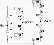
Assume opamps in this example perfect followers without intrinsic non-linearity.
Both AOUT and ABOUT here hold the same constant 2V drop across their quiescent
set networks. Currents I(R1) + I(R2) of Class A OUT must also then hold a constant
sum of Amperes. ( 2A + 0A ) = ( 1A + 1A ) = ( 0A + 2A )
But the Class AB OUT network of D1 R3 R4 D2 presents some nonlinear resistance.
That non-linearity permits both a very smooth crossing, and lower quiescent current.
( 2A + 0A ) =/= ( 0.5A + 0.5A ) =/= ( 0A + 2A )
Both amps having otherwise the same rails and current maximums...
The discrete diodes you see, could just be the emitters of your output transistors.
Attachments
Last edited:
- Status
- Not open for further replies.
- Home
- Amplifiers
- Solid State
- dumb question about class AB