I once made simulations with a tri-state delta-sigma topology that looked very promising. Never tried it in practice though. Yours seems to be a bit similar.
Properly implemented it would have advantages like lower switching frequency, lower RFI levels, improved loop stability, reduced supply pumping and decreased body-diode conduction problems - compared to two-level delta-sigma amps.
Regards
Charles
Properly implemented it would have advantages like lower switching frequency, lower RFI levels, improved loop stability, reduced supply pumping and decreased body-diode conduction problems - compared to two-level delta-sigma amps.
Regards
Charles
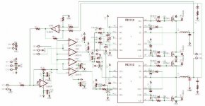
In trilevel PWM either you have 2 out of phase carrier wave to feed the comparators or you have 2 out of phase audio signal to fed.......
In your case it seems your audio signal is common and dual carriers are present but they need to be out of phase with each other.....
In your case it seems your audio signal is common and dual carriers are present but they need to be out of phase with each other.....
exactly, i use 2 carriers, out of phase 180º, triangular shape, to lower the frec, but also they could be in phase with a dc offset so they don't overlap, like the AC inverters.
i'm working in the pcbs, and i need to change the inductor because i'm using normal ferrite cores, but the magnetic fields interacts and cause a small distorsion in the high frecs. But here is quite dificult to find toroidal cores.
Any sugestion for the pcb layout
Any sugestion for the pcb layout
My estimado dcmdcm:
Cuando copies un esquematico en forma de un archivo de imagen, utiliza mejor el formato de imagen GIF o aun mejor el TIF, ya que el formato de imagen JPG distorsiona las lineas y caracteres y las hace dificiles de leer.
Aun mas, si en el formato TIF lo conviertes a 1 bit (monocramatico) y le aplicas compresion tipo CCITT grupo 4, consigues una imagen de alta resolucion, con un tamaño muy compacto.
Todas estas opciones estan disponibles en tu editor de imagenes.
English Translation
Dear dcmdcm:
Whenever you copy a schematic as an image file, it is best to employ the GIF or better the TIF image format, as the JPG format distorts lines and characters, and makes them difficult to read.
Even more, if the TIF format is converted to 1 bit (monochromatic), and you apply CCITT group 4 compression, you get a high resolution image of very compact size.
These options are available from your image editor.
I once made simulations with a tri-state delta-sigma topology that looked very promising. Never tried it in practice though. Yours seems to be a bit similar.
Properly implemented it would have advantages like lower switching frequency, lower RFI levels, improved loop stability, reduced supply pumping and decreased body-diode conduction problems - compared to two-level delta-sigma amps.
Regards
Charles
Charles,
How can you say that body diode conduction will be reduced in 3-level modulation as compared to 2-level modulation?
regards,
Kanwar
Last edited:
How can you say that body diode conduction will be reduced in 3-level modulation as compared to 2-level modulation?
Agree! Diode conduction problem depends on output topology, not modulation method.
The whole was depending on a single-ended three level output stage and the preferred way I would have implemented it would give some relief regarding reverse-recovery.
Regards
Charles
Regards
Charles
Charles,
What would be that preferred way, just like the autoformer [referring to your cross-conduction reduction technique thread]at switching node?
regards,
Kanwar
What would be that preferred way, just like the autoformer [referring to your cross-conduction reduction technique thread]at switching node?
regards,
Kanwar
No it would have been a "real" three-level output stage.
Regards
Charles
Charles,
You mean using series schottky or i am missing something?
regards,
Kanwar
- Status
- Not open for further replies.
- Home
- Amplifiers
- Class D
- 3 Level PWM