Hello
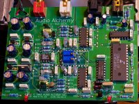
I am looking for the datasheet of this DAC because I want to tweak a Audio Alchemy "Dac In The Box". I want to know if I can supply it with +- 12 V in the analog part.
Thanks
Philippe
I am looking for the datasheet of this DAC because I want to tweak a Audio Alchemy "Dac In The Box". I want to know if I can supply it with +- 12 V in the analog part.
Thanks
Philippe
Probably, it's the same family as the AD1862:philbyx said:I want to know if I can supply it with +- 12 V in the analog part.
http://166.111.64.217/datasheet/analogdevice/PDF/1068.pdf
/Hugo
Thank you very much Hugo,
The AD1862 can effectively be fed with 12 V (13.2 max) but not the AD1865 nor the AD1861, It's quite complex, then I need the original datasheet of the 1860!
Philippe
The AD1862 can effectively be fed with 12 V (13.2 max) but not the AD1865 nor the AD1861, It's quite complex, then I need the original datasheet of the 1860!
Philippe
Dear Philippe,
hope this helps:
http://www.audioasylum.com/images/DITBschematic.pdf
http://www.audioasylum.com/images/DITBMOD.pdf
datasheet for ad1851/61 (they aare pin compatible with ad1856/60)
http://166.111.64.217/datasheet/analogdevice/PDF/1064.pdf
hope this helps:
http://www.audioasylum.com/images/DITBschematic.pdf
http://www.audioasylum.com/images/DITBMOD.pdf
datasheet for ad1851/61 (they aare pin compatible with ad1856/60)
http://166.111.64.217/datasheet/analogdevice/PDF/1064.pdf
Many thanks Dilmitri
I have all those PDF and in fact it's in the "ditbmod.pdf" that the author tells us to replace the 7805 and 7905 by 7812 and 7912. He says that the ad1860 is specified for 12 V. I just want to verify.
Philippe
I have all those PDF and in fact it's in the "ditbmod.pdf" that the author tells us to replace the 7805 and 7905 by 7812 and 7912. He says that the ad1860 is specified for 12 V. I just want to verify.
Philippe
In the 1064.pdf it says that AD1861 can be used in designs where AD1860 were used at +/- 5V.
I hope I still have a paper copy of AD1860 datasheet. I'll check and if so I'll scan it.
I hope I still have a paper copy of AD1860 datasheet. I'll check and if so I'll scan it.
Yes Jean Paul, you are right !
<<The AD1851/AD1861 is available in either a 16-pin plastic DIP
or a 16-pin plastic SOIC package. Both packages incorporate
the industry standard pinout found on the AD1856 and
AD1860 PCM audio DACs. As a result, the AD1851/AD1861
is a drop-in replacement for designs where ±5 V supplies have
been used with the AD1856/AD1860>>
This suppose that the 1860 can be used with more than 5 V, like the 1862.
Thanks
Philippe
Got it!
Hi,
Got it (i have the original datasheet books), now looking at audio/video ref manual 1992. But i don't own a scanner
Anyway:
+-5 to +-12V operation. -Vdigital may not be more negative than
-Vanalog!
You can use it as voltage out +-3V or current out +-1mA by not using the internal opamp. Maybe room for improvements..!
Currents drawn are 10.5mA for + at 12V, 13.5mA for - at -12V, only specified analog and digital together (me thinks).
Currents are at 10MHz clock.
Versions from "bad" to "good" (THD figures):
dip: N N-J N-K
smd: R R-J R-K
Optional MSB adjust:
pin 15 - 470k - pot 100k - 200k - pin 1
then pin 14 to wiper of pot
Decouple all supplies to dgnd or agnd (duh).
Example schematic shows NJN5532 or AD712 for a low pass filter
😀 😉 🙂 😕 🙁
🙁 

And it's a 18 bit device
pins
1 -V analog
2 logic gnd
3 logic +V
4 nc
5 clk
6 le
7 data
8 logic -V
9 Vout
10 feedback resistor
11 summing junction
12 agnd
13 Iout
14 msb adjust
15 trim
16 +V analog
input 2's complement 18 bit MSB first. Inputs are clocked on rising edge of clk. After loading the bits an active high le pulse .
Gr
Hi,
Got it (i have the original datasheet books), now looking at audio/video ref manual 1992. But i don't own a scanner
Anyway:
+-5 to +-12V operation. -Vdigital may not be more negative than
-Vanalog!
You can use it as voltage out +-3V or current out +-1mA by not using the internal opamp. Maybe room for improvements..!
Currents drawn are 10.5mA for + at 12V, 13.5mA for - at -12V, only specified analog and digital together (me thinks).
Currents are at 10MHz clock.
Versions from "bad" to "good" (THD figures):
dip: N N-J N-K
smd: R R-J R-K
Optional MSB adjust:
pin 15 - 470k - pot 100k - 200k - pin 1
then pin 14 to wiper of pot
Decouple all supplies to dgnd or agnd (duh).
Example schematic shows NJN5532 or AD712 for a low pass filter
😀 😉 🙂 😕
🙁 And it's a 18 bit device
pins
1 -V analog
2 logic gnd
3 logic +V
4 nc
5 clk
6 le
7 data
8 logic -V
9 Vout
10 feedback resistor
11 summing junction
12 agnd
13 Iout
14 msb adjust
15 trim
16 +V analog
input 2's complement 18 bit MSB first. Inputs are clocked on rising edge of clk. After loading the bits an active high le pulse .
Gr
Many many thanks Guido, you made a very good job for me !
I have the answers to my question!!!
May I ask you a little thing more :
Can you compare the specif of the ad1860 and the one of the ad1862 ?
I think they are quite the same?
Philippe
I have the answers to my question!!!
May I ask you a little thing more :
Can you compare the specif of the ad1860 and the one of the ad1862 ?
I think they are quite the same?
Philippe
The 1862 has a 'digital offset circuit'. Think it is patented, the databook talks about patents which are not for the 1860.
numbers 4.349.811 4.857.862 4.855.618 3.961.326 4.141.004 4.902.959.
It shifts the midscale output away from the point of msb transition.
No internal opamp as in the 1860. Different pin-out obviously.
So i think they are quite different apart from 18-20 bit.
Regards,
numbers 4.349.811 4.857.862 4.855.618 3.961.326 4.141.004 4.902.959.
It shifts the midscale output away from the point of msb transition.
No internal opamp as in the 1860. Different pin-out obviously.
So i think they are quite different apart from 18-20 bit.
Regards,
Hi Gudio
Did you ever get around to scanning the AD1860 datasheet. If so - can you please send me a copy. I think you have my email address.....
Did you ever get around to scanning the AD1860 datasheet. If so - can you please send me a copy. I think you have my email address.....

May be it a mistake?
Because AD1860 best among AD1851/1856/1860/1861
and it has 18 bit.
PCM61 (analog AD1860 and AD1861) has 18 bit and its monotonicity 16 bit.
Because AD1860 best among AD1851/1856/1860/1861
and it has 18 bit.
PCM61 (analog AD1860 and AD1861) has 18 bit and its monotonicity 16 bit.
vasiltech said:
Thank you very much 🙂
URL is death. I will attached here.
What about the sound character of this DAC device from Audio Alchemy ?
Attachments

Last edited:
Hello, here is the actual link:URL is death.vasiltech said:has placed it here:
www.vasiltech.nm.ru/files
vasiltech.narod.ru/files.htm
Last edited:
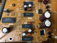
Can anyone tell me if these chips in the photo are the same asad1860n-k? The chips are printed ad1860-k. The datasheet of the ad1860N does not have this type. They are used in a sony player in parallel with 2 chips per channel. I am wondering why Sony did not implement dual differential mode.
Attachments
- Home
- Source & Line
- Digital Source
- AD1860 datasheet for Audio Alchemy DAC