What is the concern?
LL1545a spec said it does 10Hz-70kHz +/- 0.5dB @ 0dBU
If you have a high impedance source there would be some roll off at low frequency. The suggested max source impedance is <600ohm.
When a 10k pot is used, the maximum source impedance (when the pot is set to -6dB) would be 5k//5k = 2.5k
At normal listen volume, the 10k pot source impedance would become <1k.
I think it should be ok. This is just a simple approach, using active preamp is better.
now we have some real substance in this thread. this information is what i was looking for. cover all the options. i like it already. so it seems you have been doing some transformer homework lately alex. if you like the schematic you have here i may try it. using the transformer with a few other discrete components could yield a truly hi end interconnect. with the exceptional stats on your amp i do not want to add some garbage and mess it up. to me diy means quality.
0 dBu = 2.19V peak to peak according to http://www.sengpielaudio.com/calculator-db-volt.htm
The transformer can handle up to 22dBu (27.5V p-p) but the THD will go up to 0.2% @ 40Hz, which is quite a bit of distortion. However you won't have 27V at line level.
In terms of frequency response and THD performance, DRV134 is a lot better. Some people may not like DRV134's sound, but I found it is ok.
tryonziess said:now we have some real substance in this thread. this information is what i was looking for. cover all the options. i like it already. so it seems you have been doing some transformer homework lately alex. if you like the schematic you have here i may try it. using the transformer with a few other discrete components could yield a truly hi end interconnect. with the exceptional stats on your amp i do not want to add some garbage and mess it up. to me diy means quality.
Hey, I just give some options and ideas, I don't know which will sound best, so you (and us) have to try! 😉
Hi ALEXW88
Hi I'm new to the comunity and is very interested in building BPA300. Can you please send me the Schematic and gerber files? The .MAX would be best. I found a place that can fab out boards on the cheap. (www.gojet.com) I have OrCad so I'll be able to read them.
Thanks in advance
John
Hi I'm new to the comunity and is very interested in building BPA300. Can you please send me the Schematic and gerber files? The .MAX would be best. I found a place that can fab out boards on the cheap. (www.gojet.com) I have OrCad so I'll be able to read them.
Thanks in advance
John
I don't have the complete schematics, see this post if you want one, Algar_emi has made one :
http://www.diyaudio.com/forums/showthread.php?postid=1254199#post1254199
Attached is the Gerber file.
http://www.diyaudio.com/forums/showthread.php?postid=1254199#post1254199
Attached is the Gerber file.
Attachments
Sorry for the newbie questions.
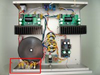
But, do you just connect the outputs of the transformer (+/-30V) directly to the 47000uF caps?
http://www.shine7.com/audio/bpa300_2.htm
I can't tell how the power supply is connected. See last picture from the link above.
A schematic would help out a lot.
Thanks in advance.
John
But, do you just connect the outputs of the transformer (+/-30V) directly to the 47000uF caps?
http://www.shine7.com/audio/bpa300_2.htm
I can't tell how the power supply is connected. See last picture from the link above.
A schematic would help out a lot.
Thanks in advance.
John
The Bridged rectifiers are fasten to the front paneljohncmng said:Sorry for the newbie questions.
But, do you just connect the outputs of the transformer (+/-30V) directly to the 47000uF caps?
Thanks in advance.
John
No. Transformer output >>> bridged rectifier>>> capacitors
Attachments
http://www.coolcircuit.com/circuit/powersupply/basic_dual_power_supply.GIF
You can leave out the noise cancel,if you want.
You can leave out the noise cancel,if you want.
alexw88 said:How about this setup? At the preamp you have both RCA and Balanced input.
Between preamp and power amp, you only have balanced connection.

For balanced inputs and outputs, the preferred method is to connect the cable's shield to chassis ground, at the point of entry, NOT to signal ground. See http://rane.com/note151.html .
- Tom Gootee
http://www.fullnet.com/~tomg/index.html
alexw88 said:If you use transformer you don't need input cap.
More about gain -
If DRV134 is used, the BPA300 gain will be 40.
If a 1:1 transformer is used, the BPA300 gain will be 20.
If a 2:1 transformer is used, the BPA300 gain will be 10.
Hii Alexw88
Glad to see you today
can i ask you about the statement
Wheres the input cap we must cancelled
( size : uf / v )
Thank you alex
Hii again
If i look your kids in website is so cute, happy family
I read about your plan to experimental with lundahl weeks ago
how the result alex ? i think that the best result !
Alex can you group buys again for Lundahl PCB
i believe all people trust with your experimental
why ?
we got the best for lundalh PCB like the channel
( same colour, same manufacturing )
All DIY will buy from you cause your prize is cheaper
They can take care until they have saving someday
Is there enough for 2 boards bridges with 1 transformer?
If yes maybe i order 2, jopie with order 2 whos next ?
Pls help us alex
Hi Jeffry,
> can i ask you about the statement
> Wheres the input cap we must cancelled
> ( size : uf / v )
I don't understand what you mean.... The input cap I used is 15uF/400V.
BTW, I have not tried the lundahl in my Amp yet, and if I do, I would just do a point to point wiring without laying out a PCB.
Alex
Hi,
re post 71.
the post shows Alex88 schematic for a balanced connector box that can be used for an unbalanced switchable input.
This circuit depends on accurate matching of the resistances between the two phases of the balanced circuit. Pots connected as shown can never achieve sufficient accuracy to maintain balance and the advantages that balance brings to the input scheme.
Most of the attenuation, of unwanted signals, offered by balancing the signal will be thrown away by using POTs.
The receiver expects to see accurate matching of source resistances and source impedances to better than 1% and preferably <<0.1%. It will also perform better if these source impedances are low throughout the audio range.
The source expects to see matched high resistances and matched high impedances throughout the audio range.
This matching is what the switching and pots completely destroys.
I recommend active preamp if you use ll1545a in the BPA300. Major Issue with passive pre is high freq roll off, see my LL1545a measurement page for details.
Getting a pot which built with 1% resisters is not a problem. You can use 0.1% but it would be expensive.
Getting a pot which built with 1% resisters is not a problem. You can use 0.1% but it would be expensive.
that is a switched attenuator.alexw88 said:Getting a pot which built with 1% resisters is not a problem. You can use 0.1% but it would be expensive.
If that is what you are recommending, then the schematic should state that requirement and also point out the disadvantages of using pots.
This amplifier is impressive. I love it!
But in Brazil is very hard to find some components like, toroidal transformers, smd components like and others.
I wanna know how much you paid for all components without the case, and pin conectors. And ask if you will make more pcbs and sell then.
But in Brazil is very hard to find some components like, toroidal transformers, smd components like and others.
I wanna know how much you paid for all components without the case, and pin conectors. And ask if you will make more pcbs and sell then.
I don't have the exact cost for the parts, I guess it is about $300-$400 per mono block. Sorry I don't have any more PCB for sale.
- Home
- Amplifiers
- Chip Amps
- BPA300 mono block finished and measured