Looking for a broken LS3/5a

I like the Quad ESL57 a lot and I keep reading about LS3/5a being speakers owners of those like. I'd like to swap in Falcon drivers and crossovers so really just looking for something where the drive units are in poor condition/broken. Please send me a PM if you want to discuss it since I'll receive an email notification. Thanks :wrench:

Edit: I will add that as long as I haven't updated the thread to say I've found a pair, this thread is essentially still open to looking for them, so feel free to send me a message at any time.

Ppi pc 2350 keeps blowing sound card / Please Help

Hi all . So I have a Precision Power PC.2350 amp that I recently replaced all of the power mosfets and the output transistors . I get a clean sound wave at both channels with no load connected . At low volumes both channels sound beautiful
When connected to a speaker . But the problem I have is that when I start to raise the volume loud but without clipping the sound wave . I have burned up the same sound card 2 times . These sound card are really not repairable to my knowledge and I don’t have any more to risk blowing up . At this current moment I have replaced the sound card with my last spare one and both channels sound great again . Can Some please help guide me ?

Is there anything I can put in line of a power to class D amp to stop the pop noise?

Is there anything I can put in line of a power to class D amp to stop the pop noise on power-up?

Hello all. I would really appreciate some help here being an DIY newbie builder. I have just put together a simple class D amplifier which is powered by a 24V DC power supply. All is good if you turn the amplifier on via its click rotary volume control. However, if you leave it turned up to where you want it and power it off via the mains and back on via the mains power switch it makes a 'not nice' pop to the speakers.

Being a 'electronics know very little' 🙂 Is there anything that I can put in line with the power to the class D board perhaps that will stop this pop happening? A gradual let the power through type of thing perhaps that may prevent it? (links to ebay or whatever would be much appreciated to a newbie builder). I'm assuming its from a surge in and a slower power up would perhaps prevent it doing it.

All I want is to leave it powered on or power on without using the rotary volume as its just going to be adjust and left at a set volume. I'll have a separate preamp to control volume.

Switch off pop, JBL mpx1200

I have two JBL mpx1200 amps which are making sometimes very loud pop/noise from speakers when turning off. No inputs connected. Otherwise amplifier works perfectly. There is output/speaker relays but they are possibly too slow when turn-off spike appears.

Here is the power input schematic, would it be good idea to put X2 rated capacitor(s) or series RC snubber or MOV accross primary windings AFTER the power switch? There is just one 0.47uF before switch.

IMG_20200831_184906.jpg

200 hertz Tractrix Horn Mold

I used Tractrix _V1.4b to design a 185 Hz horn using Inlow sounds .inlowsound.com method of making a mold and building the cones out of paper mache. I am not connected to them in any sense. I have never communicated with him either. Although it probably would have been a good idea. I did just finish and pulled the second horn off the mold. I do not have storage space for the mold and am willing to make someone a terrific deal. It has a 55mm throat and is 610mm in length and 594mm diameter mouth. It is painted with catalyzed urethane automotive paint. Sanded smooth with 2000 grit and polished. I am using Dynaudio D54af for drivers but a low frequency 2" compression driver would be better. I hate to take a hammer to my covid 19 lock down work, but it has to go soon. I have learned a few things and can pass that along as well. I am located on the Southwest coast of Florida. I will part with it for the price of the paint $125.00

Attachments

  • 20200423_135413.jpg
    20200423_135413.jpg
    600.2 KB · Views: 562
  • 20200504_102955.jpg
    20200504_102955.jpg
    688.5 KB · Views: 553
  • 20200603_131032.jpg
    20200603_131032.jpg
    886.2 KB · Views: 542

Mercedes GLB sound system upgrade | NEW tech vs OLD tech

Hello all,

I'm getting a new Mercedes GLB as my company car, to use for the next 3 years.

The car has no extras (basic version), and has the basic 110w sound system (6 speakers total - 1 tweeter and 1 woofer on each front door, and 1 woofer/full-range on the back doors).

I want to upgrade the sound quality (with a limited budget (~750USD) since the car is not mine), and three options were presented to me, by the several car audio shops I talked to:

A) Install a DSP amplifier (e.g. MATCH PP-62DSP or M5DSP MK2) and maintain the stock speakers

B) Install a "regular" amplifier (e.g. ESX QM400.4), and change only the front speakers (e.g. Morel Maximum), keeping the back speakers stock - I could also add a simple subwoofer for about ~100USD extra on my budget

C) Change all 6 speakers for a "good" set (e.g. Focal Performance) and maintain the stock amplifier - cheaper option

From what I read, the trend now is people to install DSP amplifiers.
However I feel I would get a better sound quality with option B than from option A.

Since I'm no expert, what should I go with the stock speakers and only a "new tech" DSP amplifier (option A), or put an "old tech" amplifier and new front and subwoofer speakers?

One of the shops gave me an alert about doing this hybrid solution (B), saying that the Mercedes car system would block the sound or event play it very low on the front/amplified speakers (since it would detect this power change has a "short circuit").

What do you think?
Should I go "new tech" or "old tech"? Option C? Or even a D one no one told me about?

PS: I am from Europe, I usually listen to vocals and accoustic/unplugged music (via CarPlay or USB flacs), and I usually drive alone.

DCD-960 upgrades

I recently acquired a Denon DCD-960. There are plenty of threads that touch the DCD series, but none that I've seen that includes the 960, or the x6x series. I'm handy with basic electronics and soldering, but most of the DAC-related stuff in CD players is over my head.

What's the best way to improve the analog output section of the 960? I plan to do some recapping, but I'd like to know what circuits to cancel, and whether replace DCD-960 with better DACs and op-amps.

I attach a couple of images with schematics and a list of ICs in case it's helpful.

Circuit Board

ICs and transformers

Bryston 3B Transistors check and replace

I have an old Bryston 3B pro with blown fuse on the right channel 🙁 .What I did:
1/ Replaced 5A fast acting, plug in with light bulb limiter, bulb lit up bright.
2/ Removed right channel module, plug in, bulb dim.

I intend to check the BR6522/ BR6521 and SJE1490/ SJE1491 but I am not really sure how to remove them for checking.
My questions: (I am a beginner, bare with me please.)

1/ Is there any way to check them without remove from circuit (I think less likely)

2/ If not then these steps I would want to take:

- Desoldering all 6 transistors.
- Remove 8 screws which attached transistors to heat sink
- Remove 8 screws which attached metal case to heat sink.
Let me know if these are the right way or any thing I am better watch out as beginner may miss.


Thanks,
Troy

Attachments

  • 20200820_134110 (Medium).jpg
    20200820_134110 (Medium).jpg
    239.6 KB · Views: 501
  • 20200826_140109 (Medium).jpg
    20200826_140109 (Medium).jpg
    188.7 KB · Views: 541

Adcom GFA-5800 Broken Left Channel

Hello everyone,

Nothing is visually damaged on this board, I have measured the DC coming from the PSU and compared it to the right channel and it’s correct, even the LEDs light up, I have also noticed that they stay lit much longer than the ones on the right side after turning the Amp off.

I’m not a Pro, I got 2 of these amps because of what they represent and I was hoping I could fix them but with the very little information I could find about them it looks like I chose the wrong Amp to learn 🙂

Any suggestions from those that have seen something similar?

Any common issues that I should be tackling first?

Thanks in Advance!!

BMS 15n630 good for sub duty?

Hi! I’m looking for some advice if BMS 15n630 can be used in closed box of approx 80 liters for subwoofer duty? The high Fs of 39 concerns me, so a «standard» Q of 0.7 in the 80 l box simulate a f3 of about 75Hz... A BR box of 90 l will help the response down to approx 45 Hz. I would like some more extension, preferrably closer to 30 Hz. I know the room will help. And EQ could also compensate, but I can only adjust the crossover frequency (Parasound Hint + bridged Behringer for the sub).

Any thoughts or advice is appreciated!

Powering on Kardon PM660

I am almost positive I had a short on the tone board (my fault...), power amp section seems to work fine if I press 'tone direct' but no sound through preamp.
I pulled all the transistors on the tone board and tested them using the diode function on a MM. Initially I thought the 2SK170s were bad but I may have been testing them wrong. Regardless, bought 4 new LSK170s from Linear Systems. Also replaced the 2SC1845s with KSC1845s since I had them lying around. All the other transistors tested good, which concerns me as I expected to find something toasted.

Paranoid about frying the LSK170s as they are expensive. I have a DBT and a cheap variac I just bought, anything I should watch out for when I power it up? I also have the preamp section disconnected from the power amp for now.


Was planning to just use the DBT and give it a go but thought I would do quick post to see if there was anything else I should be thinking about.

Sealed Speaker Enclosure Vas > Qts Confused

Hello,
So i am struggling to get to grips with sealed speaker enclosure volume math.
I have read and read and some is starting to make sense, plus this little tool is proving a great help.
Speaker Box Enclosure Designer / Calculator

But what to do when Vas is less than Qts as in:
Vas = 0.9l
Qts = 1.04
FRS 8 - 8 Ohm | Visaton

or
Vas = 0.3l
Qts = 1.28
FRS 7 - 8 Ohm | Visaton

or did i miss something (probably)?

Many thanks in advance imk

Op-Amp Input Stage Design

For my next project, I decided that I want to eliminate the need for a closely matched input pair by using a FET input op-amp instead. I figure it will be an interesting thing to experiment with.

It's far from a new idea- the amp that my design is based off of is the Crest 1001A- which dates back to the 1980s. The schematics for the Crest are attached for reference. Adding a triple EF output stage seems to drastically reduce distortion (at least in simulation).

The design attached simulates quite well, with a few issues that need to be addressed going forward. First is stability- 36 degrees of phase margin seems a little borderline to me. From what I can see, the phase shift is occurring before the output stage.

The 10K square wave simulation looks good, and shows a slew rate of about 85 V/us, which is plenty.

I still need to work out the details of VI limiting on this design, but its implementation shouldn't be much different from any other amp.

I'd love to hear suggestions regarding improvements to this design, particularly from those who have played with this topology before. I'd certainly like to get a bit more of a phase margin if I can, and I'm certainly not opposed to improving distortion.

Attachments

  • Current Configuration.JPG
    Current Configuration.JPG
    109.4 KB · Views: 918
  • Bode.JPG
    Bode.JPG
    108.6 KB · Views: 868
  • 10K Square.JPG
    10K Square.JPG
    66.6 KB · Views: 740
  • 10K Square Rise & Slew Rate.JPG
    10K Square Rise & Slew Rate.JPG
    53.8 KB · Views: 721
  • Phase Shift.JPG
    Phase Shift.JPG
    73.5 KB · Views: 791
  • Crest Topology Simulation.asc
    Crest Topology Simulation.asc
    8.6 KB · Views: 99
  • Cordell Models.txt
    Cordell Models.txt
    19.5 KB · Views: 84

Lundahl OPT Ringing - To Damp or Not to Damp

I have a question related to ringing of output transformers. I have observed this behavior in two different transformers from Lundahl in two different designs, the LL1620 3.3K 60mA and LL9202 6.5K 50mA.

In both cases, the ringing was isolated to the output stage, no visible ringing on the previous stages. Mains transformer ringing is snubbed in both cases.

Here is a 1kHz and 10kHz square on the LL1620 primary.

YVS83lC.png


GdanoQ0.png


And 1kHz and 10kHz square on the LL9202 from the primary.

qsgDqPT.png


SyqAq10.png


Is it worth pursuing a Zobel network or similar to further damp the ringing? On the LL1620, looks to be near the audio band on the 10kHz square.

Hill Audio Sliding bias

The last couple of days I was reading a book about power amp designs and one of the designs mentioned was the hill DX700.
It had to do with sliding bias and a special kind of drive to the output using a transformer.
The driver driving the transformer was just a chip amp (TDA2030).
Looking at the distortion specifications it doesn't look really bad.


Has anyone used these? and comment on the sound?
I do like to check out some of these more obscure designs.

What would a modern version look like?
A few things for modernizing could be a more modern chip amp (lm3886?), using a class H output but still using the sliding bias arrangement if possible.
Use a Sziklai output stage instead of just driving the outputs directly.
Less loading of the chip amplifier so less distortion I think.

I'm just thinking out loud now but the design looks like it worked good so why isn't it used anymore? I am still in the process of figuring out how exactly the sliding bias works

Might RS270P-4A 10" Paper Woofer work in Karlson enclosure?

I have just built some foamcore Karlsonator speakers (0.53x) using W5-2143 drivers - they exceed expectations - and would like to add a pair of subs to these, using a Karlson design as well. Not in foamcore, of course.

I'm just wondering whether the drivers I have - Dayton RS270P-4A (Reference paper 4ohm units) might work in such an enclosure?

Has anyone any experience with either these drivers or similar in an appropriately sized Karlson enclosure?

The mains get to about 50Hz in room so if I can get the subs down to about 25Hz that would be more than adequate.

Failing that, I have RSS265HO-44 and RSS390HO as single sub alternatives.

Specs:
Nominal Diameter10"
Power Handling (RMS)100 Watts
Power Handling (max)200 Watts
Impedance 4 ohms
Frequency Response 23 to 6,000 Hz
Sensitivity 90.9 dB 2.83V/1m
Voice Coil Diameter 2"

Thiele-Small Parameters
Resonant Frequency (Fs)22.9 Hz
DC Resistance (Re)3.9 ohms
Voice Coil Inductance (Le)0.55 mH
Mechanical Q (Qms)1.35
Electromagnetic Q (Qes)0.34
Total Q (Qts)0.27
Compliance Equivalent Volume (Vas)3.9 ft.³
Mechanical Compliance of Suspension (Cms)0.66 mm/N
BL Product (BL)10.9 Tm
Diaphragm Mass Inc. Airload (Mms)73.2g
Maximum Linear Excursion (Xmax)6 mm
Surface Area of Cone (Sd)346.4 cm²

DC coupled driver/spliter prototype: will this work?

Hi guys,

I am working on an idea of having a fully DC coupled design input driver stage / phase splitter.

The idea is to use a 6AU6 in triode (I like that tube), DC coupled to the first section of 6SN7, that one DC coupled to the second section of that 6SN7 used as a classic phase splitter. I know cascading sections in DC coupled mode can be challenging, but that's all part of the fun.

On simulation, this works, quite well.

Any glaring mistake you guys see in this design?

I know the current in very low in all 3 tube sections an this could create problem, especially with the LED fixed bias component. If this become a problem, I can always come back to a classic cathode bias resistor.

Also I want to keep the splitter design.

Thank you
Brice.

Attachments

  • PROTO-DC.jpg
    PROTO-DC.jpg
    206 KB · Views: 325

Rohde & Schwarz UPL 16 Loses Hard Drive Config at Power Down

This morning, I powered on my UPL analyzer only to be greeted with no hard drive detected and CMOS battery failure.

I have the recollection that when I serviced this unit last year, I changed the lithium battery on the computer board. But I'm not 100%, so I pulled the UPL out of service, pulled the cabinet off, removed the speaker and unbolted the motherboard. Took the old battery out, tested it. It shows 3.1 volts. Hmm. I MUST have put this battery in last year.

Needless to say, since I had it apart, I put in a new battery (after checking that it read over 3.1 volts) and put it all back together.

Booted it, and put in all the disk parameters and launched the analyzer software. To check things, I shut off the UPL, waited 15 seconds, then powered it back on, only find out that it lost the CMOS setup for the hard drive and was complaining still about a CMOS battery failure.

This is the only battery I can find on the entire analyzer. What in tarnation is going on here??

NRG Control 400wpc Class A Monoblocks, What to do? Repair or upgrade?

I recently got hold of a pair of these monster mono block amplifiers and documented the story on Audiokarma...

I got them from a scrap dealer and as expected they didn't work. The problem appears to be that the same pcb in both amplifiers has been messed around with by someone in the past. One has had parts removed, the other has had incorrect bits added.

The problem is no schematics or circuit diagrams exit for these amps, and every tech I have contacted has said they can't help.
I have tried to contact anyone related to NRG control to no avail.

At 55kg , with 48 output transistors and a transformer larger than a brick each , I REALLY want to get them working, even if it isn't practical to use 400w class A amps everyday, one day I might just have a use for them.

The original plan of hoping a tech could figure out the problem without a diagram didn't work.

Next I thought about reverse engineering the pcb and drawing a circuit diagram from that, but it would take ages AND only give me the diagram for that particular board, there are 2 other similar sized boards + all the outputs + the power supply section which would take far too much time to draw out...

The latest idea was to build a clone of a more popular amp, like a Krell KSA 250 based around the power supply and chassis of the NRG amps....

Can anyone advise...?

Attachments

  • nrg 1.jpg
    nrg 1.jpg
    84.2 KB · Views: 1,149
  • nrg4.jpg
    nrg4.jpg
    99.3 KB · Views: 1,130
  • nrg3.jpg
    nrg3.jpg
    78.6 KB · Views: 1,114
  • nrg5.jpg
    nrg5.jpg
    79.3 KB · Views: 1,084
  • nrg6.jpg
    nrg6.jpg
    92 KB · Views: 1,097

Bobbins for EI-120 Lamination

Hi folks!

I am facing a dilemma. I have bought M6 grade EI-120 lamination mostly for winding power transfomers and chokes. Now I have to choose bobbins, but unfortunately seller packing only one size per shipment.

I added a size for all available bobbins, of course for power transformers the bigger bobbin the better, but for chokes the bigger size probably will be overkill.

What size do you think will be optimal for EI-120 lamination?

Attachments

  • sizes.png
    sizes.png
    64.5 KB · Views: 205

Marantz PT rewire EU/US to US only

Hello. Model CD275 with VSS: designed with a Voltage Selector Switch for int'l use. Thanks to fellow member 'joydivision' for assistance to get started. I want to eliminate the VSS and hardwire to the PT. The 1st attachment are his instructions for rewiring primary leads.The Marantz schematic found in HiFi engine doesn't show wire insul. colors & I need help. Thank You. Today: 03 Sep, with a magnifying glass I was able to see molded numbers on the interior of the green switch plate of the volt. adaptor corresponding to schematic numbers. One step closer. I apologize for the non viewable pictorial attachments. I will try again.

Anybody from Köln that can help me with an "ebay-kleinanzeigen" purchase

Very briefly:
I would like to buy and send me a tangential turntable which I've found at the local ebay site in Germany.
The selle won't ship: only will deliver on hand in the nearby of Köln or pickup. I've tried hard to convince him but with no succes🙁
If there is anybody at the diyaudio forum from Köln that can give me a hand, I really appreciate your help.
Just drop me a PM and I'll come back with more details.
Thanks (danke) very much in advance for yor time and interest.
John

FS:Stanford SR785 2 Channel Dynamic Signal Analyzer

Hi all !
A dynamic signal analyzer that has been idle for many years, I have not conducted a power-on test at this time, and I am not sure whether it is operating as expected. The current state I am planning to handle at a low price, $1000.00
The project location is in China.
Of course, if the buyer has a request, I can ask the engineer to do a detailed test. But it will increase the cost of testing.
Let's take a look at the internal state first:

Attachments

  • IMG_4124_调整大小.JPG
    IMG_4124_调整大小.JPG
    116.4 KB · Views: 210
  • IMG_4128_调整大小.JPG
    IMG_4128_调整大小.JPG
    89.7 KB · Views: 212
  • IMG_4129_调整大小.JPG
    IMG_4129_调整大小.JPG
    79.6 KB · Views: 209
  • IMG_4130_调整大小.JPG
    IMG_4130_调整大小.JPG
    128.5 KB · Views: 219
  • IMG_4240_调整大小.JPG
    IMG_4240_调整大小.JPG
    154.7 KB · Views: 202
  • IMG_4243_调整大小.JPG
    IMG_4243_调整大小.JPG
    175.2 KB · Views: 76
  • IMG_4241_调整大小.JPG
    IMG_4241_调整大小.JPG
    165.4 KB · Views: 86
  • IMG_4242_调整大小.JPG
    IMG_4242_调整大小.JPG
    85.6 KB · Views: 89
  • IMG_4244_调整大小.JPG
    IMG_4244_调整大小.JPG
    137.5 KB · Views: 89
  • IMG_4245_调整大小.JPG
    IMG_4245_调整大小.JPG
    189.1 KB · Views: 91

Idiot proof output transformer switching?

I want to switch between output transformer taps and also between output jacks. It’s for a tube based headphone amp/preamp. Since I won’t be the only person to use this device, I would like to make the switching as idiot proof as possible. I’m envisioning someone playing with the switches at full gain and trying to imagine what might go wrong. The goal is to avoid shorting across the secondary winding or leaving the secondary unloaded. What do you all think of the attached schematic? Overkill or not? Is there a better way?

Thanks,
Marty

Attachments

  • TRANSFORM SWITCH.jpg
    TRANSFORM SWITCH.jpg
    50.3 KB · Views: 203

Combining Vented and Bandpass Boxes

Someone emailed me about a box design they saw online.

So I thought I'd put in some time to show what I think it's doing.

In a nutshell, you can combine vented and bandpass enclosures and achieve some interesting results.

ywGUWma.jpg


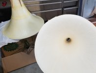
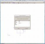
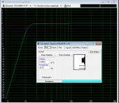
Here's a sim that shows the combination of a bandpass box and a vented box. The woofers are the same, an Alpine SWS-10D2.

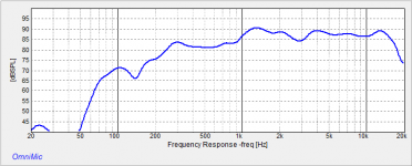
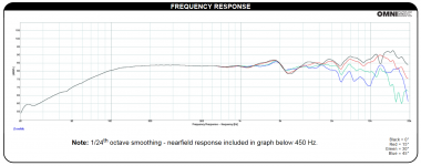
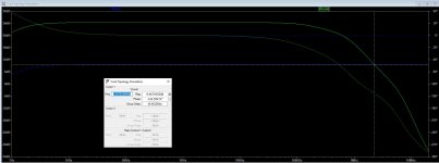
In the frequency response, you can see that the response curve of the two boxes are comparable. If their phase is identical they'll sum constructively.

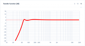
Because one is vented and one is bandpass, you might think that the phase response would vary. But with some juggling of the parameters, you can get it fairly close. These two boxes have a group delay curve that's basically the same, down to 35Hz, so they WILL combine constructively.

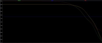
Below 35Hz, the phase of the two boxes varies quite a bit. This is because the vented box sees 180 degrees of phase shift at it's tuning frequency. At 35Hz, the two boxes are 135 degrees out of phase.

This situation can be addressed fairly easily. For instance, you might use a steep high pass on the bandpass box, so that it's output is reduced below 35Hz. The bandpass box is already radiating 3dB less output than the vented box at 35Hz, so attenuating it another 6dB probably wouldn't be a big deal.

Another option might be to manipulate the phase using FIR filters, all-pass filters, or just plain ol' active filters.

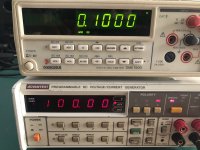
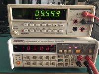
To me, the most interesting aspect of the design, by far, is that the impedance of ONE subwoofer is very high when the OTHER one is LOW, and vice versa. This really has the potential to increase your maximum output, if the two subs share the same amplifier. For instance, at 51Hz the bandpass box is receiving 500% more power than the vented box. At 30Hz, the vented box is receiving over 200% more power than the bandpass box.

So this becomes a "yin yang" thing, for the amplifier, where one sub is drawing a ton of power at a frequency, while the other is not.

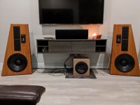
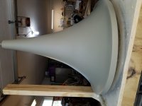
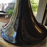
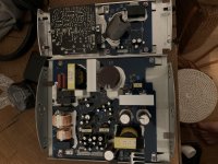
In my old home theater, I had a tapped horn, a vented box, and a bandpass box, all at the same time. That worked really nicely, and operates on the same principle.

This thread was inspired by a discussion here:

https://www.diyaudio.com/forums/subwoofers/359383-active-compliance-management.html

Advice and Suggestions for very high BL woofer

Hello

Recently I could pick up two vintage Goodmans Woofers as well as other components from an old estate.

Id like to build a new enclosure, as the speakers were mounted in the furniture and did not come with a cabinet.

Tested the woofer in free air and some 140 L sealed enclosure that was lying around, to check them. The go up to 4-5 kHz, are very! sensitive but are difficult the get any deep bass from.

They seem to be very special model with very high BL and very low Qes. Id like to hear about any experience with high BL / low Qes Drivers anyone had.

Some info on the woofer

Goodmans Audiom 852

Size 12 inch, 313mm overall diameter
Weight 26 lbs, 11.8 kg (heaviest 12'' speaker I ever laid hands on)
Total flux 308000 Maxwells (highest number I've ever seen)
Fs 35 Hz
Re 15.8 Ohm and 15.6 Ohm (Highest I ever measured)
3'' voice coil

By comparing with other modells, 308000 Maxwells would correspond with 16'000 Gauss flux density. Taking in account the Re and comparing with other Goodmans woofers I would estimate a BL of around 32.

Does anyone have experience with such woofers?

Thanks a lot for any info.

Martin

Attachments

  • Audiom 852.jpg
    Audiom 852.jpg
    405.6 KB · Views: 234

Mitsubishi M5218AL as a.....?

I came across a Mitsubishi M5218AL (SIP 8 pin) amongst my junkpile of stuff.
It's a very low distortion dual op amp mainly used as a headphone amp in some equipment.


I'm curious, and open to suggestions before I go into anything with this, but would it be possible to use this chip as a pre-driver of sorts to drive some hefty output transistors directly, or with an additional transistor before the outputs?

Attachments

ScanSpeak 30W/4558T and 30W/0-00 sub failure.

Hi all,

Today I finished a subwoofer for my car using the Scanspeak 30W/4558T and 30W/0-00 in a 70.8 litre (2.5 cubic foot) enclosure. The box uses 19mm MDF and is heavily braced, I made allowance in the box volume for the bracing, sub and passive radiator displacement and I covered the walls in 25mm convoluted foam. The amplifier is a 600 watt Class D that is very clean and well behaved, I have the input sensitivity turned well down.

The result is less than good, the bass is tubby, one noty and the the sub seems to overload at even low volume. I haven't measured it yet but I can not live with it as is. Would anyone care to hazard a guess as to what I might have done wrong or what is going on here?

Thanks.

Restoring a couple of Quad 2s, and DACing the Quad 22!

Hello all,

New project, just took ownership of a couple of Quad 2 monoblocks and the Quad 22 preamp.

Will be restoring the Quad 2s to 'like new' and well in hand on that..but.

For the Quad 22 pre-amp, no benefit in restoring that value tech, so want to install a MQA capable DAC into it and a more current value pre-amp.

Looking for suggestions on DAC PCBs, and tube kits/design with tone and filter controls, so I can keep the Quad 2 exterior as standard.

Thanks in advance.

Malcolm

Attachments

  • quad 2.jpg
    quad 2.jpg
    113.1 KB · Views: 85

Is that a weird use of opamp ?

Hello, I came across this schematic.

https://www.electroschematics.com/mosfet-audio-amplifier-irf9530-irf530/

To my understanding, the opamp is loaded with the 240ohm resistor, and the signal is taken from the current consumption of the opamp ? Is my understanding correct ? Is that really smart or really ugly ?

Thank you 🙂

Attachments

  • weird.gif
    weird.gif
    66.6 KB · Views: 475

Tube noob - help with vintage el84 conversion

Hi all, after much lurking and reading got inspired to take on my first tube project.

Looking for some guidance with a vintage single ended el84 amplifier. This was pulled from a Motorola record player, the objective is to convert it to a stand alone stereo amp.

I've done the following so far: replaced power cord with grounded 3 prong (no death cap in the circuit that I could see), added on/off switch and fuse holder. Have also replaced all power filter and coupling caps.

I am not intending to use the old volume, tone or balance controls. The amp uses 2 12ax7s in the pre-amp stage, one half of each tube appears to be for gain ("1st AF Amp) and the other is labelled "Tone Amp". Both driver tubes have connections back and forth to the tone control panel.

And this leads me to my question, upon reviewing the wiring and schematic I'm not sure where to wire my inputs for stand alone use? Do I need to use both driver tubes to get adequate gain or can I bypass the 'tone amp' triode section on each channel (if not using the tone controls)? I'm pretty sure there may be some re-wiring involved but looking for the simplest way to get this running.

Attaching the schematic, any help much appreciated.

Attachments

  • Motorola SH12 schematic.jpg
    Motorola SH12 schematic.jpg
    377.7 KB · Views: 186

Question: lacking low bass & mid-bass in this full range design

I recently finished my second speaker build, but the listening experience and tests with an OmniMic system reveal an unexpected lack of low-end. Given that the drivers are only 3 1/2", I wasn't expecting a lot of bass, but the it had substantially worse frequency response than the driver manufacturer's specs. How did I go wrong?

Design details:

  • Two Dayton Audio PS95-8 full range drivers.
  • One port that is ~6" long and 2.5" in diameter with a flared end.
  • Box has ~650 cubic inches of interior volume after taking drivers and components into account. I calculated the ideal volume as 775 cubic inches, and I may try stuffing the box with some kind of acoustic treatment to "inflate" the perceived volume.
  • Uses a Dayton Audio DTA-2 Class D Digital Audio Amplifier Module.
Attached images:

  • Two frequency response results I got from measuring the finished product with OmniMic. One is at a higher SPL level.
  • The frequency response of the driver, supplied by Dayton.
  • The low-end response of the box, as calculated by Speaker Box Lite.
  • The finished box to give a sense of the design.
My analysis:

The driver frequency response from the manufacturer is flat until about 100Hz. The calculations I did with Speaker Box Lite estimated a port tuned to about 66Hz would keep the response flat down to about 50Hz.

To my dismay, the finished product seems to start dropping off at ~1kHz. When listening to music, the low end is pretty absent. Kick drums lack body and baselines are hard to pick out. Any help understanding what is going on here would be greatly appreciated! :worship:

Attachments

  • bookshelf snapshot 1.png
    bookshelf snapshot 1.png
    9.8 KB · Views: 255
  • bookshelf snapshot 2.png
    bookshelf snapshot 2.png
    9.5 KB · Views: 256
  • Screenshot_2020-09-01 295-349--dayton-audio-ps95-8-spec-sheet pdf.png
    Screenshot_2020-09-01 295-349--dayton-audio-ps95-8-spec-sheet pdf.png
    142.4 KB · Views: 272
  • Screenshot_2020-09-01 SpeakerBoxLite Subwoofer box calculator, Sub box calculator.png
    Screenshot_2020-09-01 SpeakerBoxLite Subwoofer box calculator, Sub box calculator.png
    42.5 KB · Views: 243
  • IMG_20200901_214835066.jpg
    IMG_20200901_214835066.jpg
    906.8 KB · Views: 364

2way Speakers with SB Acoustics SB13PFC25-4 & SB26ST-C000-5

Started the 2way design with SB Acoustics SB13PFC25-4 Paper Cone Woofer and SB26ST-C000-5 Soft Fabric Dome Tweeters

Specs:
2way Floorstanding Speaker from 5'' mid-bass and 26mm dome tweeter.
Cabinet Volume: 8Ltrs
Woofers: SB13PFC25-4
Tweeter: SB26ST-C000-5
Nominal Impedance: 4 ohms
Port tuning Frequency: 45Hz
Cabinet Material: 6mm MDF + 12mm Pinewood
Cabinet External Dimensions: Height - 870mm X Width - 175mm X Depth - 232mm

Xover Design, Cabinet CNC Data, and Measurements will share soon

Attachments

  • 20190408_120837.jpg
    20190408_120837.jpg
    748.3 KB · Views: 1,034
  • 20190408_120552.jpg
    20190408_120552.jpg
    558.9 KB · Views: 923
  • 20190408_120619.jpg
    20190408_120619.jpg
    608.5 KB · Views: 910
  • 20190408_120700.jpg
    20190408_120700.jpg
    475.7 KB · Views: 899

Bluetooth Digital Audio Receiver

I'm taking apart an Onkyo amp from 2015. I'm breaking it into two projects. I'm building a 500W sub and a DAC with Amp for my HiFiman HE-5Se headphones. The amp has all the chips PCM, ARM processor, 128MB RAM etc. but no Bluetooth IC. I'm looking for a digital Bluetooth receiver IC, no built in DAC and pre-amp. Suggestions? I want my music to play from my phone and need to transmit and receive a PCM signal. Feedback welcome . . .

Dual triode circuit boards

For anyone who has been frustrated trying to figure out how best to physically lay out and wire a tube amp, these boards might be of assistance. The come in 9 pin, noval, or octal configurations for twin triodes. I purchased the 9 pin version (octals out of stock) to play with. The quality seems good, and they're very flexible as to the configuration. The schematic and information is downloadable.
And the standard disclaimer - I don't work for, or know, these people and have no vested interest in anyone purchasing them. Just thought I'd share the info.
DIY - www.thetubestore.com
PS - if this should be in 'Parts', I apologize, and assume someone will move it.

Help with Symetrix 544 power transformer

HI,

I friend have an old Symetrix 544 comp. But the power transformer is burned. So, I need a replacement, the problem is that I have no idea what type of transformer is. The manual have some schematics, but is unreadable. The only that can help, maybe are the voltage regulators.

78M12
79M12

78M15
79M15

Anybody can help?

Thanks.


https://i.ibb.co/mBz2fcL/IMG-20200821-193448494.jpg

What panel mount connector for dual (positive/negative) voltage power supply

Hi guys,

(I have tried the search but i couldn't find my answer, hopefully i used the right search).

I'm trying to find a panel mount connector for my phono preamp projects which should have 3 conductors for feeding power from my dual voltage power supply (positive/negative DC outputs plus ground) to the preamp .

I've been trying to locate something for a month now, and the only type of 3 pin connectors i found was XLR female (or male) panel mount connectors which i'm not sure if it's the right thing to use.

Have you any suggestion where should I look for such DC connectors ? I'm struggling with my limited electronic components knowledge...

Internal chassis brackets

I'm looking at the Mini Dissipante 3U (250mm) and the Slimline 2U (280mm alum) for two different projects and I'm trying to find information about the size of the internal brackets. From the photos I've seen, these look like they are about 10mm x 10mm angle brackets along the top and bottom and up a little on the back and front panels. Is there a drawing available anywhere that shows the exact dimensions?

Thanks.

Transconductance converted Aleph J

At last I have a successfull experiment 😀

I like transconductance amplifiers (high output impedance) and I like the Aleph J, and so of course I wanted to combine the two!

My thought process was:

  1. Start with a normal Aleph J
  2. Convert it to use a single sided supply because that is what I have: I added R51-R55 to a normal Aleph J and omitted R2.
  3. Reduce voltage feedback by X: In the end upping R4 by 4x to 820k reduced this by ~ 12 dB.
  4. Wrap a current feedback loop around it for ~ 12 db of current feedback and connect it to the negative input. Here I reduced R3 to let me use a smaller current feedback resistor in series with the speaker to waste less output power.
  5. Get the result of an Aleph J with same distortion spectrum but with high output impedance, a current source amplifier like the F1 and the F2 without impedance reducing resistors.

And in the end it worked perfectly. I get the same distortion spectrum as a normal Aleph J, same-ish output power and most importantly ~ 120 ohm output impedance instead of the 0.4 ohms of the real Aleph J.

And an additional note: With a single sided supply we need the voltage feedback loop. Without it the current feedback makes the amp oscillate. Amplifier topologies for current-drive | Current-Drive - The Natural Way of Loudspeaker Operation explains this.

Attachments

  • TransconductanceAlephJ.png
    TransconductanceAlephJ.png
    48.5 KB · Views: 573

Room equalization with Aida DSP

Hi,

I wish I could add an application for room equalization for the open source
project Aida DSP.
I've started reading here
https://www.minidsp.com/applications/digital-room-correction/drc-basics
and then here
Transfer function modeling and equalization by fixed-pole parallel filters

It seems that the measurement of the room response has to be done by Pc with audio card + Mic. Then you generate the desired compensation curve and
try to approximate it with a cascade of IIR filters, which run on DSP hardware.

I can do an application for Arduino that load DSP coefficients after a room measurement, but I need really someone who just tried some
of the existing algorithms.
The final application will be opensource and will run on Aida DSP board which is ADAU1701 based.

Thank you! 🙂

The Clone Wars

So, I have maxed out on building LM3886 chip amps and want to level up to Papa Nelson Pass Class A's.

What is the recommendation and ethical way forward for PCB sourcing ?

In particular, I plan to build an F5 as it seems to be loved by all, and is probably just what I want, a classic 25w class A.

The challenge is getting a PCB...

The diyaudio store has been out of stock for ages, ebay is full of "inspired by" PCB's that seem to claim some relationship to the original Pass design.

So what to do?

Are the diyaudio boards likely to return to stock, are they authentiic to the Pass design.

If the philosophy is "open source" are the gerber files published?

Baby Huey EL34 P-P amp ~kit~, Toroidy PT, Hammond 1650PA, Genalex KT-77, Tele ECC83

I acquired parts for this amp but have way too many projects so selling at nice discount.

SOLD Baby Huey EL-34 Kit - PCB's (2* amp, 1* psu from latest GB), 95% BOM (PDF attached with part list), Toroidy TSTA250/001 and ceramic tube sockets

SOLD Hammond 1650PA 60W 6.6K OPT

SOLD Hammond 159V Choke

SOLD Gold Lion Genalex KT-77 - $120/quad (platinum matched from Upscale Audio, used less than 20hrs)

SOLD Telefunken ECC83/12AX7 smooth plates (Fisher logos), test at 45/45, 45/47 which is 90-95% of new. $90/pr

Attachments

  • 2020-07-16 17.52.48.jpg
    2020-07-16 17.52.48.jpg
    157.5 KB · Views: 339
  • 2020-07-16 17.53.55.jpg
    2020-07-16 17.53.55.jpg
    150.5 KB · Views: 336
  • 2020-07-16 17.53.35.jpg
    2020-07-16 17.53.35.jpg
    172 KB · Views: 336
  • 2020-09-01 20.36.59.jpg
    2020-09-01 20.36.59.jpg
    208.2 KB · Views: 326
  • 2020-09-01 21.33.15.jpg
    2020-09-01 21.33.15.jpg
    236.7 KB · Views: 324
  • 2020-09-01 21.33.41.jpg
    2020-09-01 21.33.41.jpg
    207.1 KB · Views: 156
  • 2020-09-01 21.34.30.jpg
    2020-09-01 21.34.30.jpg
    212.8 KB · Views: 133
  • BOM - Baby Huey EL34.pdf
    BOM - Baby Huey EL34.pdf
    54.6 KB · Views: 79

need help finding an opamp IC in "PDIP" form

I'm fairly new to this stuff and I'm building a preamp for my truck (semi). I thought I was so smart and ordered the ICs and sockets I need from mouser.com, to find that only one of the ICs I ordered was in the correct form for my use (apparently "PDIP" is what I need). That was the TI DRV134 (DRV134PA). The others, the INA134 and the OPA1602, I inadvertently ordered in some sort of miniature board-mount versions. I was able to find the correct version of the INA134 (INA134PA), but they don't have the OPA1602 in any version that is not a miniature board-mount. I need it from Mouser so I don't have to wait for shipping (I live not far from them).

Does anyone have a suggestion for an opamp IC that I could easily find in the larger PDIP form?

To answer a question this may have raised, yes I have a balanced line source and a receiver with balanced inputs. Both of these are in rear areas of the cab and are part of a fairly complex system I am building.

BIG caps

I found two of these nippers between my stuff today while cleaning out drawers. They are Siemens styroflex caps, 200000 pF, 500V. Two caps in parallel with a small bypass cap in the center. I see some guy's like to install monstrous caps on the input of an amp, maybe I should try it sometime !😀

Attachments

  • IMG_20200828_183538.jpg
    IMG_20200828_183538.jpg
    422 KB · Views: 194
  • IMG_20200828_183551.jpg
    IMG_20200828_183551.jpg
    460.5 KB · Views: 184

Dayton 10" Reference pair built

Not much to say, but plenty of picts. Kit goes together well and is a fantastic bargain. Only modification I made was to create additional roundovers on all the front and top edges. The baffle only has a roundover on the left and right vertical edges from PE.

And that white Duratex finish is really excellent! Goes on nice and smooth and gives an easy, consistent finish.

Attachments

  • box parts.jpg
    box parts.jpg
    276 KB · Views: 240
  • box build 2.jpg
    box build 2.jpg
    253.5 KB · Views: 240
  • box cat.jpg
    box cat.jpg
    284.9 KB · Views: 234
  • box woofer test fit.jpg
    box woofer test fit.jpg
    251.4 KB · Views: 236
  • box roundovers.jpg
    box roundovers.jpg
    209.7 KB · Views: 223
  • box in place.jpg
    box in place.jpg
    190.2 KB · Views: 143
  • box primer.jpg
    box primer.jpg
    239.8 KB · Views: 158
  • box white.jpg
    box white.jpg
    222 KB · Views: 127

Op amp oscillation advice

I've finished constructing a simple SE SS amplifier, see attached schematic, from here: A Failed Successful Experiment.

Powered it up, checked voltages, all looked good. When listening to it I heard a high pitched whine which made me think it was oscillating. Put it on the scope and yes, oscillations. With NE5534 in place oscillations are at 1MHz, with a TL071 350kHz, and with a OPA227 1.4MHz.

Supply decoupling is good (100nF right at the power pin and 100uF a centimeter away). What should the next troubleshooting step be? A small cap across the feedback resistor?

Thank you!

TubeCAD headphone.png

Puzzling Amplifier Power Problem

Hello all.
I have a problem that I have been dealing with for the best part of two weeks and I'm literally at my wits end.

This is my setup:
I have a 2007 Honda Crossroad. It has a Pioneer Carrozzeria AVIC-RZ77 head unit. I have installed a Fusion CA-AM20350 Class AB 1000w 2 channel amplifier and a 400w 12" Fusion EN-SW12ES Subwoofer.
* I have run an 8 inch section of 4 gauge wire from the positive terminal on the battery to a barrel fuse holder with a 40amp fuse. From the fuse, the 4 gauge wire runs to the amplifier for power.
* I've run another piece of 4 gauge wire from a bolt under the seat connected to the chassis to the amplifier for ground.
* I ran the remote wire from the head unit to the amplifier.
* The head unit has one sub out RCA which I've connected a 1 female to 2 female, and then 2 male to 2 male RCA into the amplifier.
* The speaker wires run feom the amplifier to the terminal connector on the back of the subwoofer box and then inside to the subwoofer.

Okay, on to the problem:
The entire system runs beautifully, the bass is amazing - until I start the car. Once the engine is running, the amplifier has a 'Power Protect' light that goes red and the subwoofer plays nothing at all. The minute I switch the engine off, the light goes green and the subwoofer springs to life. Start it again, same problem, no subwoofer. What's weird is that the day I installed it all, it stopped when I started the car. As I drove, it started working again. When I braked at times, the sub cut out and it came back a while later, this repeated a few times. I thought I had a bad ground, so I adjusted the ground and now it does not work at all if the engine is running.

This is what I have tried:
* I have run the system with no RCA's connected to the amplifier.
* I have run the system with the subwoofer wires disconnected.
* I have bridged the power and remote wires.
* I have run the system with no remote wire
* I have run the system with no wires at all other than the power and ground.
* I installed a switch on the remote wire so that I could switch the amp on after the car starts in case of some kind of power surge while starting the engine
All of these result in the same, problem, green light when the engine is off, red light when the engine is running.

The voltage at the amplifier reads 12.35v while the engine is off and 14.63v when the engine is running.

What has me stumped is that it works fine when the engine is off, so the amplifier seems fine.

Any idea what could be giving me this problem or what I may try in order to find the problem? Your help would be amazing, thanks in advance.

Source for high speed motorized pots

Hi all,

I'm currently trying to add much needed programmable EQ to a project.

One of the more obvious ideas I had was to try using motorized potentiometers, I found a part by ALPS, the RK168.. looked alright, was planning on adding a small DC bias on the input and using the ADC of a small micro on each pot to control the motor and hence add the programmable aspect by building off that. Only problem is, I see the RK168 had a rotational speed of 12sec/300deg, which is way too slow for my application.. needs to be more like 1sec/300deg (max) for my application. I noticed another part by ALPS with higher rotational speed, the RK25t, but it seems like it may be out of production as I can't find it anywhere.

So, I'm just wondering if anyone knows of any sources for something similar? The real appeal of the RK168 was the price per unit of around £10. The 100k value I could have worked with also, going much lower would become a bother however.

Cheers!

How to use FQP3N30/FQP3P20 and other MOSFET .subckt spice models in LTSpice

There are many mosfet models out there that are in a PSpice format and are .subckt. No worry they can still be used in LTSpice really easily. There are countless models from IRF, Fairchild/ON, Diodes Inc/Zetex, Exicon....
They all have a line that starts something like

.SUBCKT FQP3N30 2 1 3

  1. First add the proper NMOS or PMOS component.
  2. CTRL+Right Click the component
  3. Change the Prefix box by adding an X (see screenshot)
  4. Change the Value to the name in the .subckt line (see screenshot)
  5. Add a .inc statement with a .txt or .lib file with the .subckt models that can be downloaded, or copy the text and place it on the file itself

Attached a zip with example of FQP3N30 and FQP3P20 in an example circuit described on PassDIY to calculate Vgs.

Attachments

  • FQP.zip
    FQP.zip
    2.1 KB · Views: 275
  • Screenshot from 2019-06-08.png
    Screenshot from 2019-06-08.png
    231.9 KB · Views: 400

sub amp and power supply board recap

Hello Guys,
This is my first post, so any help would be dearly appreciated.

I opened up my faulty b&w pv1 subwoofer.
The power supply and amp board are covered in low quality SMG capacitors, rated at 2,000 hours 85 degrees.

Im totally lost - it took 2 hours just to open the subs (due it being and glued together) The amp board is a b&o ice power 500A (won't be recapping that)

so while I have this thing open I plan to replace all of the caps. Can someone please recommend the best caps to use. ie which Nichicon, Panasonic cap series to use.

Thank you for your kind assistance

Attachments

  • IMG_6551.jpg
    IMG_6551.jpg
    984.1 KB · Views: 246
  • IMG_3493.jpg
    IMG_3493.jpg
    488.1 KB · Views: 268

Helper transformer

I know wiring transformer secondaries in parallel is a big NO. However, what about if they are isolated by a bridge like so (see pic).

Please note the differing voltages of T1 and T2 ... the idea is as the T2 rails sag with load, a helper transformer T1 , can provide support at rail minus 2 volts and keep it better regulated. I just happen to have several transformers available and wondering how to utilize them in power amps.

Attachments

  • Capture.JPG
    Capture.JPG
    69.4 KB · Views: 234

Design advice for floorstander

I am looking for some inspiration on a good enclosure and FR combination for my needs. These are as follows:

Room is about 4.5m x 5.5m. Seating position about 3m from the wall. It has solid timber floors which are on joists/peers (subfloor space). 2.5m high ceiling. Couch seating so needs reasonable soundstage/off axis performance.

Amplifier which I am currently building is Class A (JLH69) which will have about 7-8watts with my power supply. But I would also like to be able to use for listening to tv through my AV receiver. I don't have space for 2 sets of speakers. I will make a switch box with a 4PDT toggle switch to switch between amp and AV receiver.

I would like them to be floorstanders, but not too large. I'm thinking of a 4-4.5 in speaker. Something with high sensitivity which is suitable for good quality low volume listening at night when kids are asleep. Something also with a good low f3 (not expecting miracles).

I have 6 solid 20mm veneered particle board doors (heavy) from our renovations which were coated in clear varnish so plenty of free material to work with.

So far the Frugel Horn Mk3 and L'Stylo designs have caught my eye for their dimensions (tall and slim) and aesthetics. Speaker wise I am open to ideas. I have been looking at the FE126NV for its sensitivity and the MA CHR-70. MA CHN-70 also as it is cheap but I haven't found any detailed reviews.

Any advice or opinions welcome but I do have a budget of sorts for the speakers (< $100 each) unless I really can't get what I need in that price range.

Any overall major difference to performance of a compact folded horn design vs a bass reflex of comparable size for FR speakers?

Help select 'Q'

I'm building a sub and sat system. There is a 2-way system for the sat and is succesfully built. The sub is got from car subwoofer. It has a built-in passive low-pass crossover where crossing point is at 120 Hz. For the first time listening without additional sub to sat crossover, it gave me satisfied but for a long time listening I'm thinking to build the high-pass crossover for the sat. Currently, I have the stocked components: 3.5mH and 5.6mH inductors, 68uF and 220uF capacitors. I know that it's not correct to build crossovers without basing on driver's specific data or measurement, but this project needn't to be perfect, just a system for a pc set up for game playing or listening to music in some times. From online calculator, it yields 4 combinations with different crossover points and Q as follows:

3.5mH + 68uF --> 326 Hz, Q = 1.12
3.5mH + 220uF --> 181 Hz, Q = 2.01
5.6mH + 68uF --> 258 Hz, Q = 0.88
5.6mH + 220uF --> 143 Hz, Q = 1.59

I'd like to ask for your opinion which one would you choose among these combinations?

FS:ADVANTEST Programmable DC Voltage/Current Generator TR6142

Hello everyone!
The TR6142 is Good condition and normal operation. $400 includes shipping costs, shipped to the world.
The item is located in China and supports Ebay transactions.

Attachments

  • 微信图片_20200829112138_调整大小.jpg
    微信图片_20200829112138_调整大小.jpg
    123.3 KB · Views: 75
  • 微信图片_202008291121382_调整大小.jpg
    微信图片_202008291121382_调整大小.jpg
    92.8 KB · Views: 72
  • 微信图片_202008291121383_调整大小.jpg
    微信图片_202008291121383_调整大小.jpg
    104.9 KB · Views: 80
  • 微信图片_202008291121384_调整大小.jpg
    微信图片_202008291121384_调整大小.jpg
    125.8 KB · Views: 74
  • 微信图片_202008291121386_调整大小.jpg
    微信图片_202008291121386_调整大小.jpg
    124.5 KB · Views: 73
  • IMG_0419_调整大小.JPG
    IMG_0419_调整大小.JPG
    178 KB · Views: 52
  • IMG_0420_调整大小.JPG
    IMG_0420_调整大小.JPG
    181.2 KB · Views: 55
  • IMG_0421_调整大小.JPG
    IMG_0421_调整大小.JPG
    170.8 KB · Views: 50
  • IMG_0422_调整大小.JPG
    IMG_0422_调整大小.JPG
    174.5 KB · Views: 41

Audio interface

I'm a long-time college radio DJ, used to working in an air studio broadcasting live. Pandemic has the studio shut down and many of us are producing ~3 hour music-with-mic-breaks shows at home, one way or another. So far, I've mostly been cloning MP3 recordings of shows I did within the last couple years, editing mic breaks, adding a song here and there, using Audacity on the PC.

I want to expand and create more new content instead of just re-doing old shows. I therefore bought a USB turntable and a USB condenser microphone. In the same room where I'm working I have a couple of daisy-chained 301 disc CD players.

In creating shows it is best to have as close to a live show generation scenario as possible, so you don't have to futz with equipment, settings in software, etc. but instead work smoothly, efficiently and with as little adjustment as possible as the process enfolds. IOW, the show creation process should be as close to live in-the-moment as it was in the air studio as possible.

I figure I can maybe facilitate this with an audio interface. A couple of our DJs have Focusrite Scarlet 2i2 audio interfaces and are using them to create their new shows. I see that Behringer makes competing products (such as the Behringer U-Phoria UMC202) and Focusrite has other models.

Do I need an audio interface? Will it really help me or is it really unnecessary?

I figure I can run line out from the CD players into a USB soundcard I already have, being the Behringer UCA202. If I do that, I have 3 USB sound sources:

1. mic
2. TT
3. CD

Will Audacity sort that without difficulty or will an audio interface make the process of generating shows easier? If so, would a more complex interface be better, i.e. with 3 sources? Suggestions, explanations appreciated, I've never had or used an audio interface.

For Sale Open Baffle Speakers

For Sale Open Baffle Speakers

I built these open baffle speakers myself. They are known as Manzanita 12 inch design.
Here is the link for the design: https://www.diyaudio.com/forums/multi-way/110583-fast-fun-inexpensive-ob-project.html

Here are the build specs on the Manzanita 12s:

  • Peerless SLS 830669 - 12" Woofer
  • Seas 27TDFC tweeter
  • Sledgehammer 12mH 15 gauge inductor
  • 0.8 mH aircore inductor
  • 12uF film capacitor
  • 25 ohm 5W resistor
  • Binding posts
  • 3/4 wood for baffle, base and side wings. MDF or plywood, chipboard, etc.
I am moving because of my job and since I don’t use these speakers I am selling them. They have been in storage and under cover. Since shipping these as complete speakers units is unfeasible I will disassemble them and sell them as complete speaker component assemblies (minus the cabinets) to build your own speakers. Built with quality components with a cost of $350.00 dollars I will ship them at my cost for $275.00. I will mount the woofers together (cone side) with standoffs so they don’t get hurt. Everything will be packed securely. Paypal is best.
Thank you.

Attachments

  • IMG_1525.jpg
    IMG_1525.jpg
    215.8 KB · Views: 348
  • IMG_1527.jpg
    IMG_1527.jpg
    276.1 KB · Views: 355
  • IMG_1528.jpg
    IMG_1528.jpg
    313.4 KB · Views: 352

10" subwoofer enclosure is too big

Hey all, I'm new here 🙂
I've used winisd to design my first subwoofer using dayton 10" RSS265HF-4.
I tried to tune my vented speaker to 22Hz and I got a ridiculously big sub in size 30x60x60cm to make it to the required volume of 0.08m^3.

Can anyone tell what I did wrong? I saw speakers much smaller than this at 35x35x35 in size.

Attachments

  • dayton1.PNG
    dayton1.PNG
    216.2 KB · Views: 341
  • dayron2.PNG
    dayron2.PNG
    75.7 KB · Views: 339
Projects by fanatics, for fanatics
Get answers and advice for everyone wanting to learn the art of audio.
Join the Community
507,833
Members
7,890,148
Messages

Filter

Forum Statistics

Threads
406,340
Messages
7,890,148
Members
507,833
Latest member
GaDysh