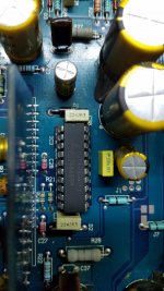
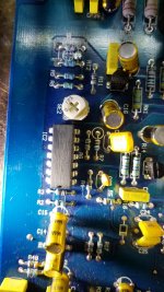
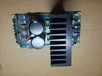
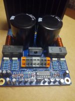
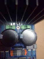
Is this cheap jfet buffer any good?

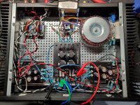
I have an ICEpower 50ASX2 which is sounding good, but I want to try adding a buffer.
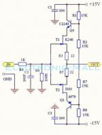
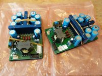
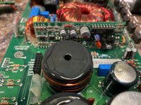
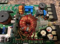
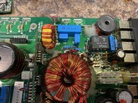
I bought a cheap jfet buffer board which is found all over eBay and AliExpress for $10 or so.
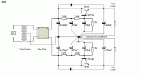
It uses 1x C2240, K246, J103, and A970 per channel.

If I use a good power supply such as an LT3045/LT3094, will this buffer do the ICEpower justice?

Alternatively, I just found an unfinished buffer PCB in my collection - the Joachim Gerhard buffer -
https://www.diyaudio.com/forums/group-buys/216669-joachim-gerhard-filter-buffer-es9022.html
This uses 2x BF862 and 2x MMBFJ309 per channel.
My only hesitation with this board is the need to solder 12x tiny SMD resistors!

Attachments

  • ebay-buffer.jpg
    ebay-buffer.jpg
    68 KB · Views: 586
  • ebay-schematic.jpg
    ebay-schematic.jpg
    26 KB · Views: 617

McIntosh XR16 help

Yrs ago I replaced the 8" midrange speaker in my fathers XR 16's. I used a parts express speaker rated at 91.5 dB. The XR16's at rated at 89 dB. I got rid of the small little plastic backing (sealed ) thing. It appears as though the upper area of the inside of the speaker is open to the bottom of the speaker with a "slot" that runs the entire back of the speaker about 3 " wide. It is stuffed with fiber fill.
The problem is that the area covered by this 8" ( 250 -1.6kHz ) is down by about 6 dB.
Could this be because the volume of the "back chamber" for the 8" speaker should only be a small amount?
I would guess the size of the plastic part I got rid of ( yrs ago) would give the volume to be about one liter.
Thanks

Paul

JFET opamp for buffer

Hi ,

I'm in the process of building a Pass B1 buffer for my DIY amplifier (probably based on Bonsai's SX amp) and while I'm at the buffer stage , I'm interested in building and comparing the B1 with a JFET opamp based unity gain and decide which sounds better to my ears.

I couldn't find a thread with this topic , so I was hoping someone could point me to a design for the above , and maybe even recommend a specific opamp to play with?

Thanks!

How to tame your diffractions

Hello!

I do see here quite regularly threads about diffraction but, respectfully, I have the impression that sometimes there is not enough understanding about diffractions. I am no expert either but I spent quite some time researching and simulating on this matter and I think I can share some thoughts which may be helpful.

I dont want this thread to be about the fundamental physical background of diffractions, I dont want it to be about the design of a specific cabinet and I also dont aim to make a new tool to calculate diffractions. There are already plenty.

Instead it should be about a general understanding of cause and effect regarding diffractions. I want to describe what can be expected from different measures to tame diffractions for proper sound reproduction.

I already have to apologize here because this will become quite a wall of text but at least there will be some pictures.

How to calculate diffractions
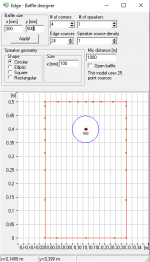
For a better understanding I think its best to start to explain how software like The Edge simulates diffractions. I am not affiliated with the software in any way so I cant say anything about the details, only how this works in general. The input for such a simulation may look like this.


attachment.php


For each point at the edge of the baffle the software calculates the distance (Source > Point at the baffle > microphone) minus (Source > microphone). For now, all my calculations will assume that the microphone is in infinite distance directly in front of the chassis. When doing exactly the same calculation in Excel, I get the following values as a function of the angle. I will call the result from this calculation distance from now on. 0° in this case is the perpendicular distance to the left edge and then every 15° there is another point at the edge in clockwise direction. It is quite easy to follow. The first 3 points are located at the left edge, each with slightly increasing distances, the next points are on top, which first decrease in distance until a distance of 10 cm is reached, representing the perpendicular distance to the top edge and so on. At an angle of about 270° three distances stand out representing the three points at the bottom edge.


attachment.php


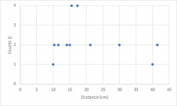
This plot can now be rearranged, because for diffractions it does not matter under which angle which distance is obtained. Only the distances themselves matter. For symmetry reasons some of the distances are the same and they can then be summarized. For example, 15°, 165°, 195° and 345° all give 15.53 cm. To ease further calculations, I can group these 4 to a single data point with a higher weighted impact on the overall diffraction pattern. I do the same for all similar distances and get then the following graph.


attachment.php


Now the effect for each of these groups of distances on the acoustic frequency response has to be calculated. Each of these groups of distances will produce a single sinus shaped deviation from a flat frequency response. For a visual representation please look at the pictures shown here Diffraction from baffle edges. When looking at the 12 cylindrical baffle in this link, you can clearly spot the sinus curve. When looking at the other pictures, you can also immediately spot that larger baffles give a higher frequent sinus curve in the diffraction pattern.

In the next step I calculate a sinus curve for each spot in the graph. I have to consider three things:
1. All curves have to have a minimum at 0 Hz,
2. the frequency is dependent on the distance and the speed of sound and
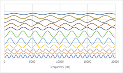
3. The amplitude is dependent on the abundance of each distance (= count). When calculating all these sinus curves individually, it will look like this. The sinus curve at the very bottom originates from the highest distance (41.41 cm).
attachment.php


Now this is audio and it a common convention to plot the frequency axis not linearly but logarithmically.


attachment.php


The total diffraction pattern can be seen when adding the curves.


attachment.php


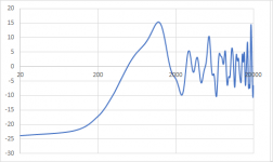
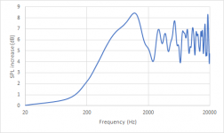
Now the scaling is a bit off. The x-axis is already fine since I considered the speed the sound when calculating Hz from cm but the y-axis is not. To fix this I have to discuss what this graph represents. To my understanding, this represents the additional sound pressure due to the half of the spherical wave which nominally is propagating to the back but is immediately reflected to the front due to the baffle, assuming an ideal point source and ideal reflectivity of the baffle. Since I used 24 points and calculated sinus curves ranging from -1 to 1 for each, the sum of them can now range from -24 to 24. -24 represents no reflection to the front (= just direct sound) whereas 24 represents full reflection to the front (= doubled sound pressure). By rescaling the reflections to range from 0 to 1 and adding the sound pressure from the direct sound, which is 1, I can calculate the sound pressure level increase when using just direct sound pressure as a reference.

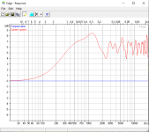
Nevertheless, it seems I am wrong on this one and if someone can explain my mistake to me, I would be grateful. For a calculation giving the same results as The Edge I have to scale the reflected sound pressure to range from 0 to 2, meaning that the reflected sound pressure can be twice as high as the direct sound pressure. With this value I then do the same as previously described: I add 1 for the direct sound and calculate the sound pressure level using the direct sound pressure as reference.

This then gives this plot, which looks very much like the result from The Edge.
attachment.php

attachment.php

Attachments

  • 1.png
    1.png
    13.3 KB · Views: 827
  • 2.png
    2.png
    6.7 KB · Views: 776
  • 3.png
    3.png
    4.3 KB · Views: 781
  • 4.png
    4.png
    39.3 KB · Views: 760
  • 5.png
    5.png
    35.8 KB · Views: 758
  • 6.png
    6.png
    13.9 KB · Views: 777
  • 7.png
    7.png
    13.5 KB · Views: 751
  • 8.png
    8.png
    36.2 KB · Views: 808

Help Hifonics Z500D hip4080

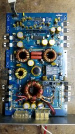
Hello friends, greetings, this time I have a Hifonics amplifier it seems nice to me and the problem here is that it could not make the hip4080 start, although I am not sure that in the output stage it has mosfets rfp70n06 and what is the license plate of the IC2 If anyone had information on this little guy I would appreciate it ... Have a great day.

Attachments

  • Screenshot_20200930-111307_Gallery.jpg
    Screenshot_20200930-111307_Gallery.jpg
    570.6 KB · Views: 185
  • Screenshot_20200930-111314_Gallery.jpg
    Screenshot_20200930-111314_Gallery.jpg
    326.1 KB · Views: 163
  • Screenshot_20200930-111323_Gallery.jpg
    Screenshot_20200930-111323_Gallery.jpg
    474.5 KB · Views: 143
  • Screenshot_20200930-111318_Gallery.jpg
    Screenshot_20200930-111318_Gallery.jpg
    933.7 KB · Views: 161

High frequency noise with DIY LM3886 build - Help

I recently built a stereo LM3886 amplifier following the guide on Circuit Basics - Arduino, Raspberry Pi, and DIY Electronics Tutorials. Except for the fact that I made my own PCBs, I followed the guide religiously, including the ground loop protection circuit.

https://www.circuitbasics.com/design-hi-fi-audio-amplifier-lm3886/

I designed the PCBs and had them fabricated before assembling the boards, only to hear a very distinct and constant ~6.3kHz and ~13kHz noise on the output. Immediately on startup, it isn't present, but then within ~3 seconds it's there and remains constant. The noise is not affected by any input signal, or whether or not the RCA cables are connected.

  1. I have played around with grounding layouts - no change
  2. I've added different EMI filters on the mains voltage - no change
  3. I've plugged it into different locations in my house (get away from fluorescent lights, etc) - no change
  4. I've swapped out the power supply for a high-end benchtop power supply - no change
  5. At one point, the V+ for the left channel was loose, and wiggling it around caused the noise to temporarily cease. Making sure every connection is tight has resulted in no change.

Attached is a picture of the amp after discovering that even with the clean benchtop power supply (transformer and power supply board disconnected), I still get the noise.

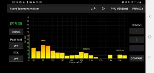
Also attached is a screenshot of as free spectrum analyzer app showing the noise (7.4k and 14k) with no signal going into the amp.

I've been searching diyaudio.com/google for other people with LM3886 noise issues, and it seems like they are all related to ground loops. If anyone has any suggestions, please let me know!

Thank you!

Attachments

  • 20201002_223750.jpg
    20201002_223750.jpg
    1 MB · Views: 357
  • Screenshot_20200929-221440_Sound Spectrum Analyzer.jpg
    Screenshot_20200929-221440_Sound Spectrum Analyzer.jpg
    106.9 KB · Views: 345

Pass Labs amp that sounds like an Aleph J

Hello all

I have recently acquired an Aleph J and absolutely love the sound of the amp. Although I would like something with more power. My speakers are Legacy Audio Focus HD, 4ohm.
I'm wondering which Pass Labs amps sound similar to the Aleph J. From my research it looks like the XA models are somewhat similar in design?
In my price range I have been considering these on the used market
xa30.5
xa30.8
Xa25

Can anyone tell me if these sound similar to the AJ or should I be considering a different model for the AJ sound signature?

To summarize, im looking for an amp with the AJ sound signature but with more fullness, weight, bloom

Thanks

Gentlemen, I'm in my first StereoWar !!11!1! in 3 decades!; and I'm kickin' arsh! ;)

Gentlemen, I'm in my first StereoWar !!11!1! 🙂 ...

.
.
.


... in 3 decades!; and I'm .. kickin' arsh!😉

Er, I thought I was too old for this crud but ... I'm a freakin' BEAST!!

😎

Let's just say that the Geddes approach is verrrrrrrrry powerful !!1!1!

.
.
.

... and I'm not just talkin' multisubs and room placement but ... the, the, ... knowledge. Sort of existential.

You know those phase switches that we manipulate to get the most in-room bass; ... and we do it in multiple interactive combinations with 3+ sub;

.
.
.


... hmmnm, well, ... just like I tell the kids re SuperPowers: These can be used for good OR for evil, I hope you choose good (wink).

This is FUN.

😉

Jeff

Subwoofer gain knob working in reverse?

I have a Mirage MM-8 here and it had some issues like bad capacitors and adhesive that had become conductive. I replaced all of the capacitors that were bad and got all of the old glue off and after plugging it in found I have clean audio output! Only problem, the volume control is in reverse?!? When the volume is at minimum I get full output and when I turn it up to “max” the actual volume goes down to fairly quiet.

The volume pot is mounted to small input board that has the frequency and phase pots along with RCAs. The Volume pot is the only one that appears to be in reverse. Anyone know what could have caused this? I’m so confused on how this could happen, I didn’t remove the volume pot.
Of the three leads in the pot, two of them are wired together with a trace, theoretically couldn’t I cut that trace and connect the middle one with the other lead?

Dan

Keeping a constant Bluetooth stream to older Alpine receiver

Hi everyone,

It's my first post here and I have a bit of a technical issue with Bluetooth on my new Alpine UTE-42BT when streaming sound to it from my Pixel 2 Android phone. It's installed in my class B camper van (and home) and wired into the house batteries so that I can use the car's audio system as a sound system whenever I want. I'll try and make this brief.

How I expect a BT receiver to work:
You pair and connect, then all sound from your device goes to the receiver and into the speakers. This is how it works with my BT headphones.

How it's currently working with my Alpine + Pixel:
I pair and connect.
I can start playing a song or a video, and the sound is streamed to the receiver and played on the speakers. The receiver knows when it's "playing" something and shows "pause" if I pause the song/video from the phone or from the receiver itself.
Once paused, certain apps, like the Android system sounds, Instagram, even some audio players playing a local mp3 file, are silent. They play on the phone but because the receiver is still in "pause" mode, no sound is playing through the speakers.

It appears as if only some apps send the proper "play" signal that audio should be played. I have found a way to trick into playing all sound: start playing from an app that works, pause it. Clear the app away, and then press play on the receiver, which will continue to show PAUSE (since it couldn't actually resume playing because you cleared that app). All sounds from the phone will then play into the speakers...until the next time you play and pause from an app that works to begin with. This is not a problem when pairing my MacBook. It just plays all sound coming from the computer.

Has anyone come across this? Is there a way to keep an open stream of audio going between the phone and receiver?

Direct Coupled driver risks and dangers

Hello everyone,

I was looking around at different driver designs for an SE 300b, when I came across a post on the JAC music website (EML tube distributor) stating that one big source of output tube failure was the use of direct coupling between the driver and output.
Jac, who wrote the post, gave no further explanation.

Does anybody have experience with this who might be able to outline the risks?

I have recently changed my voltage-amp/driver stage to one that does direct couple the output tube. This is based an a schematic that Wavebourn pointed to a while back.
Great sounding circuit. More power and less distortion than others I have tried.
(See below for schematic, if you are curious.)

Thanks in advance for your advice!

Regards,
John

View attachment 880983

New project for Hypex UcD700-AD boards

Dear Guys,

I have pair of Hypex UcD700-AD boards bought several years ago and still kept in my shelf. I am thinking kicking of a project on them. My question is:

1. With a listening area of around 15 sq meter and using horn speaker with 4" Fostex full range driver (90dB/W), will the use of these boards in my amp be an overkill and wasting of power.

2. I have one Noratel 40V+40V 625VA transformer and 6 pcs of Rifa 10000uF 63V cap in hand, will this be suitable for that. (I know the output voltage may not be sufficient and wondering if the UcD700-AD board can be operated in a lower voltage)

3. If either the transformer or the UcD700 in hand do not match my situation, I will consider selling the UcD700 and buy a more suitable pcb for your new project. Would anyone suggest alternative D-amp board that will suitable for me. (e.g. icepower or other board from Hypex,) I have try Truepath before and would like to experience the others.

Thanks in advance

Claude

Attachments

  • 20171029_160051_resized.jpg
    20171029_160051_resized.jpg
    772.7 KB · Views: 328

The Nameless Front End, or Douglas Cordell's jumper nightmare

Most people here will be familiar with the “Blameless Amp” by Douglas Self: Current source feeding degenerated LTP with current mirror load, ‘Darlington’ VAS working into Current source and driving either Darlington- or CFP-output. If the Miller compensation capacitor is split with a resistor from the middle point to the output, also called output inclusive compensation, it becomes the “Inclusive Amp”. So far so good – you can probably not get more performance from less parts.

People reading chapter 3 of Bob Cordell’s book, where he improves an amp step-by-step, will notice that the simple circuit evolves into the same topology before he ads pre-drivers, cascodes the VAS and then scales to higher power. I do not want to discuss the pros and cons of output triples and paralleling in the days of sustained gain transistors, or the “load invariant” principle, because this is about front ends from input to VAS.

But the question remains does the VAS cascode do any good? Would cascoding the input help even more, be it only by allowing faster lower voltage transistors in the LTP?

Or what about a push-pull VAS? There is a clever way to use one at the end of the MOSFET chapter (12) in Bob’s book, which avoids a double input stage by using a differential current mirror (and more cascoding). Some may have noticed the circuit is nearly identical to that in his HEC paper, apart from the OPS of course.

Now I finally come to the reason for this post. I had all those questions, plus some more, and was neither willing to populate ten perf boards, nor did I want to make ten layouts and pay for the prototypes. I spent a little more time to make a universal layout that allows testing different things selectable by jumpers (list below).

The output stage is on another board, with a connector to both ends of the bias spreader. Back when this was a company project for a customer, there were several board layouts that could be populated for Darlington, Triple or Quasi-Comp, for Diamond and for MOSFETs with and without HEC. Unfortunately, the project was cancelled, but my boss lets me continue on weekends to use up the parts and see what comes out (he used to be a HIFI enthusiast too). But again, this is only about the front end.

To allow stand-alone use, I added a class A follower with push-pull current source. This way the front end can be tested without wondering if an effect is caused by the output stage or its load. This test output can be jumpered into the feedback loop without connecting something to the VAS (one might increase the feedback divider values to keep distortion low). Also added are more possible ways of compensation.

Now this is the list of the jumpers and their function:
J1 Input DC-Coupling
J1 Feedback DC-Coupling
J3+4 IPS Cascodes On/Off
J5 IPS Current Mirror Simple/Differential
J6 IPS Lead/Lag Compensation
J7+8 VAS Current Source/Mirror (Simple/Differential VAS)
J9+10 Simple VAS (no EF = non 'Darlington')
J11+12 VAS Cascodes On/Off (J12 for Differential)
J13 Bias Spreader 2 On/Off (Driver Sense)
J14 VAS Mirror Cascode On/Off
J15 Miller Input Compensation
J16 (Classical) Miller Compensation
J17 Two Pole Compensation (+ J16)
J18 Transitional Miller = Output Inclusive Compensation (+ J16)
J19 VAS Shunt Compensation
J20 Class A Test Output active

The schematic is attached. Confusing at first, but a closer look lets you recognize the blameless topology (with half of the parts ignored), and the front end of Bob’s HEC paper. Notice it is mirrored, he used N-FETs in the LTP, which I converted to the usual PNPs. Many component values are examples or place holders, so please no discussion of dimensioning now.

Enjoy. Sample are ordered.

Attachments

Help me choose between the TSE and SSE

As the title says, I'm looking for advice on which amp I should build. I'll try to provide as much info as I can, but please let me know if I've missed anything relevant.

The increased cost and complexity of the TSE aren't really concerns. I'm confident building either amp and don't mind the additional setup and tweaking required for the TSE. Essentially all I'm concerned about is how either would pair with my speakers. My speakers are Paul Carmody's Tarkus with a larger woofer cabinet that gets me flat response at my MLP down to 30hz.

See info about the speakers here: Tarkus - undefinition
This is my measured impedance curve: Imgur: The magic of the Internet

This will be my first tube speaker amp, so correct me if I'm wrong, but from what I've read it sounds like the impedance spikes down near the tuning frequency would pose some issues for any SE amp but the negative cathode feedback on the SSE might help.

I listen to a bit of everything and I specifically built the speakers to be no-compromises full range, so low end response is important to me. I sometimes listen loud but rarely above 90dB. Carmody claim's 85-86dB sensitivity, which I know is pretty low. But I think a 300b TSE would provide enough power. MLP is about 8 feet from the speakers.

What do you guys think? Are my goals unrealistic with a SE amp? Would the SSE with cathode feedback do better than the TSE? What about the SPP? Are my speakers just not a good fit for a tube amp?

Thanks for the help!

Sidenote: What impedance OPTs would you recommend for my speakers based on the impedance graph?

DIY Class AB SS Amplifiers Top List

Hello,

Could you share most popular DIY class AB solid state amplifiers list for diyers? Sometimes we look for it that have been applied and liked by you and qualities accepted by majority.

Could you add more to the list ?

  1. The diyAB "Honey Badger"
  2. Leach Amp
  3. Slewmaster - CFA vs. VFA "Rumble"
  4. AMB Lab β24 fully-differential power amplifier
  5. Rod Elliot P3A
  6. AKSA 55
  7. Circlophone© by Elvee
  8. MikeB's Symasym
  9. David Tilbrook's AEM6000
  10. Fetzilla
  11. ...
  12. ...

My Best

Just for interest

😀..

Just read this..its always interesting to listen to others struggle..😀

The Grounded Grid preamplifier

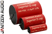
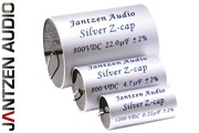
It would be interesting if anyone else has listened to Janzen Z Caps and Janzen silver Z caps what if any difference did you find..the reason I ask is
they are quite close in price..
I have just put some Z caps in a line stage ...I guess they are OK..but not close to others I have used..

This Vs This?


Regards
M. Gregg

David Eden WT500 Highway - new power amp?

Hi,

I'm considering about trading one of the bass amp I don't use with a David Eden World Tour 500 Highway with a blown power amp and/or power supply.

Looking at the schematic I would say that the preamp needs:
  1. dual 15Vdc power supply for the opamps (bypassing the quad of 5W dropping resistors, so reducing the heat inside the amp)
  2. +12Vdc for the heaters of the 12ax7
  3. dual 70Vdc for the 12ax7

I was thinking to accept the deal and invest part of the difference I'll get in euros to buy:

this power amp ( Top Iraud2000 Class D Amplifier Board 2000W Irs2092s IRFB4227 7G23A-22UH | eBay ) with the possibility to upgrade in future installing more supply capacitors.
Dimensions: 184 x 117 x h70 mm

s-l400.jpg


and this power supply ( 2000W ad alta efficienza LLC Soft Interruttore AMPLIFICATORE AUDIO POWER SUPPLY BOARD | eBay ) because it can supply all needed voltages (heater supply is a bit low with that 100 mA, I can probably ask for a customization or just install a small toroidal just for that)
Dimensions: 207 x 100 x h45 mm

s-l400.jpg


This way I will have a very light "WT-1200" bass amplifier with just 149 euros more. I'll never use that power, but I've a 4x10 speaker that can handle that power continuously and the price is very good.

Do you have some suggestions?
Thanks in advance

Attachments

diy STIPA measurement

We want to do a STIPA measurement in our church. We are going to replace the audio system and we want to compare the current setup and the new one.

The cheapest measurement device I found is a SM50 from Bedrock. That device costs 1200+ euros.
Another option a came across is an IOS app: File Not Found

That seems to be a relative cheap option. Eventually with an external mic.

What do you think about this app? Is this a good option or not worth the money?

COVID Homeschooling Speaker/s

I have a niece in Costa Rica who is homeschooling due to COVID. She uses an Apple iPad to take classes. I think it's 3rd grade so the kids are screaming and the teacher has a high pitched voice.

The homes in Costa Rica are plaster walls with tile floors. No curtains because lizards and tarantulas like to hide in stuff like that.

Sister-in-law is pulling her hair out from the screeching noise -- ALL DAY LONG. I'm thinking about sending a speaker down to them if it can help.

What kind of speaker and room placement would you design in this case?

eclipse xa5000 static from subchannel

An externally hosted image should be here but it was not working when we last tested it.
Hello I am repairing an eclipse xa5000 I recently got and when I opened it the power supply had smoked and the subchannel had shorted fets as well. I fixed the power supply and cleaned the switches for the 4 channel section. Now the amp comes on and the first 4 channels sound great.

The sub channel, however, makes a static noise that increases with the gain on the amplifier, the audio I feed to the subwoofer channel also works though. I have replaced a bunch of caps across the amplifier that either had high ESR or lower then spec capacitance. I am unable to get the static to go away with heat. the only thing that changes the tone of the static is when the heat gun gets close to the EQ controls it picks up the 60hz hum from the gun.

I am unfamiliar with icepower amplifiers and I have never had to dig into amplifiers this much. Any advice would be greatly appreciated.

FS:KCS Full Range Single Driver Speakers, Backloaded Horn. Rare Fostex 206ES-R

Pair of John Kalinowski built KCS backloaded horn speakers powered with 98dB sensitivity Fostex FE206ES-R drivers. Also included is a BNIB 206ES-R driver with new gasket and manual. All 3 drivers have received Dave Dlugos' of Planet 10 EnABLed treatment. Also included are two phase plugs from Dave, painted and EnABLed. High quality Mundorf M-Connect binding posts. Handmade speaker cabinets are beautifully veneered in cherry. 1 1/2" thick. A couple of small marks that cannot be seen from the front. From smoke free and pet free home.
Over $4300 invested. Asking $1250 obo. Prefer local pickup in DFW but can be shipped at buyers expense.


Directly driving a tweeter

I'd like to build an ultrasonic rat deterrent with some power. To that end, I drove a 20 watt tweeter with a 9 volt square wave. At 4 ohms I expected a little over 2 amps and 18 watts. The tweeter died. I expect I was too close to the rating. But is this a reasonable thing to try? If I get a 100 watt tweeter should I expect to be able to push an ultrasonic square wave through it directly with, say, 12 volts = 3 amps = 36 watts?

Finding myself here more and more...

Been finding myself cruising these boards more and more often as my audio journey grows. What an immense archive of knowledge, experience, and generosity this place is! Time to come in from the cold.

I'm originally a northern Californian (SF Bay) but live and work now for a university in Cincinnati as an audio archivist and curator for a library collection. I love almost all music, with an especially deep abiding love for jazz, soul, and Jamaican dub and recording techniques from the late 60's through the early 80's. I find the history of loudspeakers totally fascinating and speakers themselves to be totally beautiful devices; have actually been doing some research work on acousmoniums and speaker-orchestras recently.

I've owned a decent (not huge) amount of gear in the last years but have been finding that my connection to equipment itself is sorta changing. As a writer I've moved a lot and worked a lot of different jobs (metal shops, farms, carpentry). I like making things and tinkering. If I can make something (even a small thing) each day I am exponentially happier for it. I'd love to start learning how to make and measure speakers, rather than simply restoring or recapping them.

Not sure I'll be able to contribute much yet but I am looking forward to learning from folks here. Just wanted to say "heya."

Heya!

Peavey Classic Chorus 130

Hi folks. New member to the forums. Does anyone have any advice on finding schematics? I'm finding it impossible to find a schematic for a Peavey Classic Chorus 130. The actual symptoms are no sound from left speaker. Speaker itself works fine. So far on initial look over I've found a leaking cap, but would like to understand the circuit a little bit better.

Constant Current Source (CCS) For Audio Applications

Disclaimer: I'm just a lowly technician, not an engineer. Many here are well above me in areas related to the knowledge of electronics and more creative as well. However, given the prior statement, please do qualify any statements / assertions made. Don't state something as a fact without some verifiable reference, preferably a link to a professional paper / resource, or at least the name of the resource and author. To simply say 'because it sounds better' will be considered inadequate for the purposes of this thread.

----------

I'd like to open a discussion on the humble 'Constant Current Source', or CCS, as this fundamental building block relates to its uses in audio amplification.

We often see the CCS used as a source or sink for current where we want a relatively stable and defined current to flow in the face of variable conditions in adjacent areas of the circuit. Some people feel a specific arrangement offers better performance over other circuits in an amplifier, while different folks feel that even basic CCS is more than adequate for almost all needs. The idea here is not to settle any sort of dispute but rather to discuss and perhaps demonstrate, at least in simulation, what might be preferable with the where and when qualified.

Perhaps the application dictates how 'good' the CCS needs to be? Is there a point of 'good enough'? Is a better CCS always better in audio?

----------

If possible it would be nice to lay down a few guidelines. For starters:

1) Avoid exotic components. The best design is useless if the parts are made of Unobtanium. Parts should be easily available from main stream distributors. Components found in DIY-friendly SMD package sizes are fine.
2) Limit complexity. A CCS that takes more PCB real estate than the amplifier is not practical, especially if the gain in performance of the circuit as a whole is minimal. Let's target not more than two active devices plus required supporting passives unless the increase in performance is dramatic enough to warrant an extra active device.
3) Let's have some fun. Please no poo-flinging, flaming, trolling. Keep things friendly, courteous and civil.

----------

As a starter for resources:

http://waltjung.org/PDFs/Sources_101_P1.pdf
http://waltjung.org/PDFs/Sources_101_P2.pdf

----------

And attached are a few basic CCS circuits and a little of their performances. Please do point out any fundamental errors or ways to improve the simulations. Comments, ideas and suggestions?

Attachments

  • CCS Comparison Sch.png
    CCS Comparison Sch.png
    71.3 KB · Views: 4,420
  • CCS Comparison Current.png
    CCS Comparison Current.png
    78.7 KB · Views: 4,193
  • Current Variation v Freq.png
    Current Variation v Freq.png
    77.8 KB · Views: 4,095
  • CCS Comparison.asc
    CCS Comparison.asc
    2.7 KB · Views: 462
  • Cordell-Models.txt
    Cordell-Models.txt
    19.6 KB · Views: 350
  • Fairchild Models.txt
    Fairchild Models.txt
    933 bytes · Views: 302

Apt Holman Preamp (AHP)- continued

Hi gentlemen;

A tale of another AHP that I got a while back. Sticky-note on the top said one channel out. Finally opened it up a few weeks back.

It had been "violated"!! Some kind of mods to the phono stage. The volume pot unwired, reversed 180 degrees so you could get to the contacts and wired between the phono stage and an output RCA. All other functions "unwired"

Spent a few days reversing the mods before trying to figure out any problems. Here's where the sweep capability of the Amber 4400 analyzer proved a godsend. One channel was fine - filters and tone controls seemed to work as they should. The other channel showed quite a level/frequency imbalanced across the audio range. Traced the problem to a bad cap in the tone control stage. Removing it from the board showed electrolyte escaping from the bottom but hidden from view. This prompted me to replace all the electrolytics. In the process, did find one other old-timer spewing it's innards.

After this, both channels looked identical in their "operation" with the tone/filter controls. Now on to "better op amps" and power supply.

Of course I've entertained removing as many of the electrolytic coupling caps as I could and this leads to a few questions:

1. Can anyone suggest a simple way to lower the output offset from the discrete phono stage - getting 2.2 V at the input to C17 and 1.6V to C117.

2. A number of the coupling caps are to there to not allow any output offset voltage from the "older" op amps to reside across the potentiometers - volume and balance. I can get under 1mv with the newer op-amps. Would this level be OK across a pot or do we really have to have zero volts to not cause any (longer term) "scratchy" noise problems for the pots??

3. Finally - for now; what is the function of IC11 (A&B) in the output stage? It is apparently called a negative impedance amplifier?? that Holman indicated helps supply some of the signal current to the output. Never heard or seen this before - can someone please shed light on it's function.

Thank you VERY much

Charles

Tube maximum voltages

Hello everyone,

I have a question regarding the quoted maximum values of tubes in datasheets.

For example, 6L6GC specifies 500V maximum anode voltage. Is this value the maximum operating voltage level (meaning I would design an amp with a B+ of 500V when everything is settled) or a value that should not be ignored even for a transient moment?

I am designing a 2x6L6GC output stage, planning to use 450V B+. I know that the initial B+ voltage before the tubes start to conduct, can reach 495V, which is within limits. But what if the ac home supply rises to 257V as permitted (instead of 230V) and my initial B+ becomes roughly 545V? Will this damage the tube?

For instance, I have seen datasheets of EL34 quoting 800V maximum voltage but 2kV absolute peak voltage. Which makes me think that in a similar manner, all tubes could possibly withstand a 10% surge of their maximum rating until they start conducting, without any damage or loss of life expectancy. Is this valid?

Restoring B&W 2200

This may well be a lost cause, but ...

Having given me many years of pleasure (I bought them in a dutch auction 10 years ago for the equivalent of USD100!) there are now problems.

The 2200 has dual bass/mid drivers, one of which is "scraping", ie the voice coil is touching the magnet causing a rasping sound.

At first I thought it was gravity ( it gets to us at my age:xeye: ) but turning the driver through 180deg did not help.
I can fell the effect by carefully pushing the driver in at four points with my fingers. The other three do not do this.

The surrounds are not foam and look to be very good.

B&W in the UK emailed to say that these are 20 year old devices and the only info they could send me was a .pdf of the crossover pcb layout!

Worth saving? Scapping? What would you do?

Rockford Fosgate Punch 100IX

I replaced the power supply fets and outputs in this amp .

It will produce +- rail voltage

I cannot get it to produce the positive regulated voltage it’s suppose to be 15 volts I get -0.77 volts .

This is with black probe on middle leg and red probe on the output leg .

I pulled U7 thinking that was the issue and also tried 3 different regulators but the issue still remains the same . -0.77 volts


Any ideas what to check

An objective comparison of various releases of Love Over Gold

Hi,

I thought people might be interested in my evaluation of various formats of Love Over Gold, completely ignoring any subjective audiophile language and concentrating instead on evaluating the various recordings objectively.

I surprised the hell out of myself. The LP (aside from the damned pops and clicks) is as-good or better than any other release.

See Suzy's Blog: Telegraph Roads - an objective comparison of Dire Straits - Love Over Gold in various formats.

Port conical shape

Well I need a 3.5 cm wide 15cm(approx) long port for my application, so I bought this with the Intention of cutting it to length:JANTZEN AUDIO Event pour enceinte bass-reflex L 165mm O35mm - Audiophonics

When it arrived I realized that it has a conical shape like a horn. The diameter at the opening is 3.5cm exactly what I need but in the inside opening the diameter is only 2.6mm. Will this work? Why is it like this? Do I have to model my port as a 2.6cm meaning to decrease its size (that would increase the diameter though). Should I order a new port all together? I am confused.

Repairing suspected faulty board covered in potting compound?

Hi all,

I have been trying to diagnose a problem with my Sony DAS-702ES DAC (I have another thread on the subject). I am a seasoned hifi/AV/tech enthusiast but my knowledge of the more in-depth electronics is lacking sadly. I am hoping you can help!

I have a problem where there is a digital static produced by the DAC which I had narrowed down to the digital board, in particular the VCO block. If I moved the block or pressed down on the board above it, the issue would stop.

I removed the VCO block and joined it to the main board by means of some wire to see if I could troubleshoot it easier.

I have pictured it attached.

It seems that, when the digital static occurs (I'm assuming lack of oscillation meaning it can't properly lock onto the SPDIF signal, or something), I can press on the black potted area on the right-hand side, to make it stop.

I have resoldered all of the (visible) solder joints from the top, but this has made no difference.

Any thoughts greatly appreciated.

Service manual for the DAC here if anyone is interested:

SONY DAS-702ES SM Service Manual download, schematics, eeprom, repair info for electronics experts

Obviously this thing is ancient now, so no spares available.


Thank you very much.

Attachments

  • IMG_7753.JPG
    IMG_7753.JPG
    443.3 KB · Views: 117

Double blind tests of amplifiers

I had the need to decide which of three incarnations of SLAPS for bass I would go for.
I also wanted to compare the three with my Trimodal amplifier.

With an Arduino Nano, some relays and potentiometers I built a switchbox:

An externally hosted image should be here but it was not working when we last tested it.


An externally hosted image should be here but it was not working when we last tested it.

according to this schematic:
An externally hosted image should be here but it was not working when we last tested it.


At the listening position the test is conducted using this control box:
An externally hosted image should be here but it was not working when we last tested it.


This is how it done:

First the amplifiers to test are selected. It could be that you don't have all four amplifiers connected or that you already have ruled out one in a previous test.

Then you can calibrate the input levels to each amplifier. I did it by using a True RMS voltage meter on the common loudspeaker connection.

Next the button to DUT relationship is randomized. Press the buttons a couple of times to ensure that.

Then it is time for the blind test. At this point no one except the program knows the button to amplifier relationship. Keep notes.

Next the button to amplifier relationship is revealed.


It could be good to repeat the above a couple of times.
You might find that one or two of the amplifiers can be removed from the "contest" so the blind test can be easier.

Here's a youtube video on my first test.

Later, when I have found the winner, I will re-work the hardware so that I can test which op-amp is the better one for my preamplifier; is it LM4562, OPA1612 or OPA1642.

How to make 6P1P to 6V6 adapters?

Hi,


I've got a bunch of Svetlana =C= 6P1P-EV tubes laying in my stashes and a pair of Hammond JR-20 tone cabinets that needs new output tubes, four 6V6's per device. Instead of buying new 6V6's, I decided to use my 6P1P's and build adapters, using the penolic bases of worn out octal tubes and noval sockets. The 6P1P datasheet shows that the cathode, screen grid and plate connctions are brought out to two pins each. Is it advisable to connect each of the two pins to the relative pin of the octal base or is one pin sufficient? Furthermore, is it a good idea to integrate smallish cathode resistors of, say, 10 ohms into the adapters to ease tube matching/selecting?


Best regards!

Dayton RS build ??

Have pairs of these sitting around in original manufacturer boxes collecting dust.

Dayton RS28F-4
Dayton RS 100-4
Dayton RS150-4
Dayton RS 225-8


Any thoughts/ideas of what could be made into a set of relatively smalll monitors using sets of these or what "could" I do??? Just looking for ideas as I'm flatlining in the creativeness department right now.

Old Peerless 6.30" Alnico woofer identification:please help!

Hi guys!
I'm searching for informations about a vintage Peerless alnico 6.30 inch speaker, but I can't find anything about this model in the web!
This old Peerless woofer was fitted on a pair of two ways loudspeakers.
I've identified only the tweeter: it's the very famous Peerless MT-25 (or the MT-225) with alnico magnet.
No cross-over inside, just a capacitor connected to the tweeters, the impedence is 4 ohm for each component.
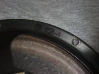
The only reference I've found is a code writed on backside, close to the magnet.
The code is: B 12-3
I suspect this speaker is more a "mid-woofer" than a real woofer.
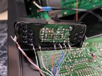
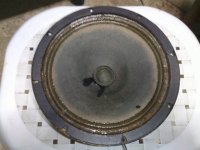
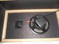
You can see some picture of these speakers below (as attached files): could you help me to identify this speaker, please?...believe me, this mistery is driving me crazy!
I can count only on your help.
Moreover, I tried to contact Peerless Company with several emails, but they never replied to me, sadly.
Thank you very much in advance to everyone for the support and the collaboration
Best regards!

Attachments

  • Peerless B 12-3 alnico magnet-speaker (1) (1).jpg
    Peerless B 12-3 alnico magnet-speaker (1) (1).jpg
    59.6 KB · Views: 612
  • Peerless B 12-3 alnico speaker-code (1) (1).jpg
    Peerless B 12-3 alnico speaker-code (1) (1).jpg
    63.2 KB · Views: 269
  • Peerless B 12-3 alnico speaker front (1).jpg
    Peerless B 12-3 alnico speaker front (1).jpg
    65.3 KB · Views: 369
  • 583.jpg
    583.jpg
    891.1 KB · Views: 381

Behringer NU6000 - Reverse Fan Direction?

Hi all,

Just wanted to check something before I do the work.

I have a few Behringer NU4-6000 amps, which cool themselves with a pair of 3" fans that just blow straight through the chassis. The air flow is back to front, and pretty much uninhibited - the chassis is pretty empty, and air is free to flow through.

An externally hosted image should be here but it was not working when we last tested it.


I'd like to use them in a rack with amps that have front-to-back cooling, so I'd like to open up the NU4-6000s and flip the fans so they also have front-to-back cooling.
They're rarely pushed to their full capacity as I use them for stage monitors, so usually 8ohm on each channel. Occasionally 4ohm.

I can see that for an amplifier with a complex cooling system that it'd be a problem, but for fans that are pretty much moving air across empty space?

Would that be okay?

TIA,
Chris

Cambridge Audio Azur 751R decoder board??

HI,

My CA Azur 751R has just returned from the repair shop.

Unfortunately, the decoder board is faulty, and unrepairable

CA in their ultimate wisdom, don't keep parts after a few years, so cannot provide another!!

Anybody got any advice? - any alternative source of parts?, or advice to attempt a possible repair/

or how much this would be worth to sell as parts??


Many Thanks

pootler.

Headphone amp recommendation needed

Hi,

I've been gone for a while and to my joy I'v found that there are a bunch of kits in the DIYStore.

Hope you guys can help me chose a kit.

What I would like is the best sounding amp for music work. In other words, the one with most clear and real reproduction of the material played.

The material will be 96k/24 bit coming from an rme adi-8 ds converter. I believe the output cables are balanced jack. I see a lot of these are rca. Hope that's simple to adapt.

The headphones I'll be using are audeze lcd-2. I think these are the Fazor version. They are the originals but one of the drivers blew and I sent it back to change for the "newer" versions which I think are fazor.

Any who, any help, comments, advice welcomed.

Thank you.

Memphis 16-MCD500

Amp came in with blown power supply fets .

I replaced the gate resistors and the fets.

I removed both driver cards in the output section along with the outputs and the rectifiers .

When trying to power the amp up the protection light just keeps flashing and the relay keeps clicking on and off .

Any ideas what to check ?

Attachments

  • 60854EAD-4241-4EAB-952F-4BE7A9C177C7.jpg
    60854EAD-4241-4EAB-952F-4BE7A9C177C7.jpg
    947.4 KB · Views: 94
  • 51C4DBDD-9B40-4250-BC1B-A98220E8768A.jpg
    51C4DBDD-9B40-4250-BC1B-A98220E8768A.jpg
    1 MB · Views: 94
  • 75F32AE8-D7DF-4FC3-9C9B-5E03BA810827.jpg
    75F32AE8-D7DF-4FC3-9C9B-5E03BA810827.jpg
    1 MB · Views: 87

Modeling analog circuits in DSP?

It's easy to transcribe an analog circuit into SPICE and get a plot of the frequency response, impulse response, distortion or other useful measurements. What I would like to do is model a particular analog circuit in DSP for real time processing of audio.

Are there any textbooks or articles which describe this technique in tutorial fashion?

I see many web sites geared towards designing a filter, but none for analysis of an existing filter or translation of an existing circuit into a software DSP model.


Case in point: I'm looking at a discrete FM transmitter schematic based on transistors and passives. There is a 15 kHz low-pass and a 19 kHz notch filter that I would like to emulate exactly in software.

The 15 kHz LP is a series of 'pi' filters with shunt capacitors and series inductors. In total, there are 4 capacitors and 3 inductors (plus a series input resistor and a shunt output resistor). Quick searches online led me to determine that this is a 7th-order filter, presumably 42 dB/octave. Analog filter design calculators even produce very similar capacitor and inductor values when asked to create a 7th-order low pass, but the pattern isn't quite the same. I'm sure this is because I found a Chebyshev design calculator and the schematic I have was probably designed using a different method. Rather than continuing to search for new methods until I find a match, I'd rather just model each passive component in software and duplicate the exact filter, as is.

There is also a 19 kHz notch as a parallel combination of an inductor and capacitor in the signal path. I'd like to model that, too. SPICE doesn't give me DSP source, just graphs, and certainly not on real time audio inputs.

Looking back at my college texts, I've almost remembered how to calculate the frequency response of a random circuit. The resulting formula would reveal the poles and zeroes of the transfer function. At that point, I could probably use Direct Form I or II to translate the formula into code.

I'm just wondering if there might be an easier way to go directly from discrete components to DSP code, perhaps without solving algebra and calculus problems.

Whats causing these trace divots after cap multiplier?

CapMultiplier.jpg

p15_fig3.gifHi,

I'm wondering what is going on with the second trace here. The top trace is a typical ripple trace taken at the reservoir capacitor. I'm getting 41 mV of AC ripple content at that point. The second trace is my final output after the capacitor multiplier circuit shown. The cap multiplier is simply being fed from a bridge rectifier with a 10000 uf capacitor (3 parts transformer, bridge, cap) voltage here is 7.07 volts and as mentioned has 41 mv of ripple (top trace).

The output of the cap multiplier is loaded with a 25 ohm resistor drawing about 210 ma. It is removing much ripple I measure 1.5 mv of ripple here (second trace), so it is nearly pure DC.

What I am wondering is why my scope is showing the little scooped divots in the second trace? My scope is in "chop mode" to show both traces.

Note I'm only using the + side of the attached cap multiplier schematic. I'm very happy to get 1.5 mv even when tested at 3 amps of draw current.

But was wondering if the second trace is normal looking for power with only 1.5 mv of ripple? It is mostly a flat line except for the divots.

Also ch 2 of my scope had to be set at under 5mv per step to the divots to show up even, if I set that channel to 50 mv per step then the second trace truly is just a straight line (DC?). Is it just that I'm setting the scope too sensitive?


ALSO: I'm not using a CT transformer like the schematic, Just a regular xformer into a bridge rectifier. Sorry I didnt re-draw the schematic.

I'm a newby/hobbyist not an electronics engineer.

CapMultiplier.jpg

p15_fig3.gif

Thanks

Looking for a KEF Q550 crossover schematic.

Hi there guys,
I'm looking for the schematic of the KEF Q550 crossover circuit. I am working on the amplifier which had the left channel blown which is used with the speaker. I am waiting for the spares to arrive. Until then I am trying to cross out all the possibilities which might have caused the fault.
Speaker driver being shorted out is one possibility as I have read. I am unable to measure this directly across the speaker terminals because I believe there is a capacitor in series and on the ohms meter I read values just like a capacitor charging.
Maybe a driver is open, resulting an impedance mismatch causing the left channel of the amp to blow? Could this be a possibility?
I haven't got access to the speakers at the moment and I would like to have a look at the schematic to make sure that in fact I wouldn't measure a driver being open or shorted out with the crossover circuit before opening up the speaker.
Thanks in advance for the help.

Silence at zero volume with LDR's

To achieve silence at zero volume with LDR's , you need to use just one gang of a 50k potentiometer, arrange the series pairs as Volume Up and Shunt pairs as Volume Down and have the wiper as the lower potential, but not directly grounded.

You then need a current source/sink , as it is a bit ambiguous, as to the nature of which, in this circuit. Some will say it has to be one or the other, but an understanding of the overall circuit will show it is both depending on the positioning of the potentiometer.

Arranged with a LM317 have the series pair cathodes at Vin of the LM317, and Adj with a resistor leading out to a higher voltage source, its value has relationship to anode voltage, so can take some discovery as all other circuit values relate ... 24k is a good value to begin with, where anode voltage is 10v

The start resistor then connects to always a higher voltage than the LDR anode voltage typically at least 2.5v higher than series anode voltage.

As the main 50k potentiometer moves toward the shunt pairs away from the series pairs, it reaches a point where the series pairs cathodes then exhibit very high, and at zero volume extremely high resistance, well beyond the manufacturers data for a NSL32SR3 Typical measurements for resistance are beyond the 200mega ohm capability of my Fluke multimeter. End result is perfect silence at zero volume , with also volume commencing where chosen.

The diagram shows a variable edition to more easily discover the needed start volume position.

I hope this helps you.

Attachments

Tweeter noise

Hi,

I have 2 amps in my car running off my Pioneer double din. Sub amp is JL audio 1000/1d and fronts run off a Rainbow Ipaul 4.300.

I have just re-routed my earth point as the old one had some loop noise, but its still there.

Can the RCA from the sub ( not very expensive one) cause any loop issues to the other RCA ( Audisson) for the fronts ?

I should really unplug it to try, but its not a 5 min job getting the hu out to test it

Any help will be apreciated

FS PA03 Pavel Dudek Gainclone PA03 LM4780

4pcs of the PA03 Pavel Dudek “De-Lux Gainclone PA03” LM4780 PCB for sale. It is posible to build a 8 channels home audio amplifier, or 4 chanel bridged/paralled amplifier. The boards are extremly versatile.

A lot about this on web, probably one of the best LM4780 amp incarnations. Since not having time, and transformers decided not to go ahead with it. The boards are completly finished, just need to be checked. See pictures for details. The boards were never turned on.


I’m asking for 400Eur in total with shiping in the EU.
Shipping with tracking can also be arranged. Instructions, can be send over e-mail, in PDF. The buyer gets 2 LM4780 more.

https://www.diyaudio.com/forums/chip-amps/35572-pavel-dudeks-upupa-epops-lm4780-amp.html

Attachments

  • IMG_20200626_055430a.jpg
    IMG_20200626_055430a.jpg
    721.6 KB · Views: 656
  • IMG_20200626_055449a.jpg
    IMG_20200626_055449a.jpg
    657.8 KB · Views: 658
  • IMG_20200626_055455a.jpg
    IMG_20200626_055455a.jpg
    807.4 KB · Views: 671
  • IMG_20200626_055505a.jpg
    IMG_20200626_055505a.jpg
    531.6 KB · Views: 633
  • IMG_20200626_055516a.jpg
    IMG_20200626_055516a.jpg
    438.2 KB · Views: 598
Projects by fanatics, for fanatics
Get answers and advice for everyone wanting to learn the art of audio.
Join the Community
507,807
Members
7,889,176
Messages

Filter

Forum Statistics

Threads
406,280
Messages
7,889,176
Members
507,807
Latest member
Mark1979!