PA Woofer Box Enclosure (2x Dayton Audio PA255-8 in Parallel)

Hi Guys,
I am working on a LCR home theatre build (3 way speakers) using pro-audio components.

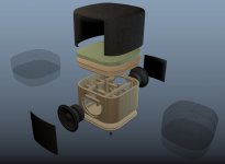
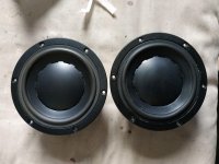
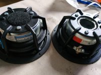
I am using the Dayton Audio PA255-8 which I hear are very good, I will be wiring 2 of them in each box parallel to give me a 4Ohm load.

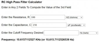
My plan is to cross them over at 600hz and I would like to have a tuning frequency of 40hz.

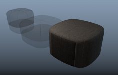
Based on online box design the box should be 3cu/ft (shared space) and port should be 4" diameter and 2.5" length. Can you help me out and confirm is this is correct? Or recommend better design?

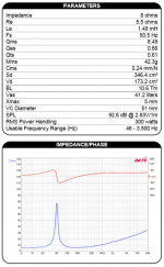
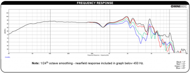
The details of the components are attached.

Attachments

  • Specs.png
    Specs.png
    150.5 KB · Views: 172
  • graph.png
    graph.png
    147.7 KB · Views: 195

Breaking ground loop?

I am trying to build a simple circuit to break a ground loop I am having on my pedalboard. I came up with this. This is put into a box so wires will not be exposed. Eventually on mini circuit board. I have two diodes 6a 500 volt and a 1 k resistor. I tested the circuit. It conducts power but is not eliminating the ground loop. The loop on the amp is fine. I have ine pedal and the power supply is a voodoo lab pedal power. It is isolated transformer type. Here is a pic of the schematic and the actual build. Can someone give me an idea why this is not breaking the ground loop? All units are being plugged into the strip. I broke into a household variety power strip and oassed tge ground wire through circuit. What am I missing?
9237-AF4-B-FE13-4-EA8-B36-E-1-A258-BC108-BF.jpg

2-AEA456-A-2-AD8-4-E29-9-A27-43454-C3-B694-A.jpg

Roksan Kandy CD repair

Hi All,

I noticed my Roksan CD started skipping the other month, extremely intermittent, only the very occasionally jump on a song and nowhere in particular (ie not the same length trough every CD or related to particular CDs), but still extremely frustrating when listening!

So after a bit of forum surfing I decided to remove the cove and mechanism and add a little white grease to the moving parts that could have become dry over time. this seems to be the least invasive but most cost effective first try at a fix.

So my first question was going to be - will I be able to open the mechanism (CD tray) without power to get to the gears and rails more easily. I have the mechanism out but I cant figure out how to get it open and don't want to force it and break something. ( this might be a trivial question for you all but this is the first player I've opened that not a PC CD drive 🙂 )

Now my second more pressing question is - Once I looked back into the case after removing the mechanism there was, what appears to be, a tiny ball bearing sat in the bottom of the case. I've taken the best picture I could with a case screw for size reference but cant upload for some reason (ill add them later), with a vernier it measures 0.54mm. Does anyone have any idea where this could be from and could this be the reason for the occasional jump whilst playing?

Thanks in advance,

Sam

amp to amp issue

Firstly, I apologise if this is a dumb question...I'm new at this. I bought a used amp to power my home theater subwoofers as the previous plate amp wasn't quite gutsy enough. I connected my sherwood RD6505 home theatre amp to my 4 x 12" rockford fosgate subs via the new AM XA1400 amp. Amp came on, no sound came out. As far as I know, all connections and settings for bridged operation are correct. Question is, is the lack of sound due to the difference in output/input ( 1K ohm and 1V from home theatre into 20K ohm and unknown voltage of amp), using unbalanced RCA to balanced XLR adapters, or is there another incompatability between home stuff and pro stuff I'm unaware of.

Soldering iron, rework station, T10, T12, 8xxx?

I know there are many threads on this, but can't hurt to ask my specific question.
Been looking for a new iron, have seen the recommendations for a T10. Recently, have decided that I also want to get a rework gun.

So, among the many options available on ebay and ali, what would be the best way? Get a T10 or T12 with just a standalone rework gun? Is a T12 as good as a T10? Get one of the myriad rework stations available, which have so many model numbers I will call them 8xxx? Are the irons on the rework stations as good as a T10 or T12?

Any insight appreciated. TIA

OPT comparisons - Not quite budget, not quite high end

I'm currently planning out a future 300B SET build, and I'm running into some analysis paralysis with output transformers. I'm investing a nice chunk into this build, but still trying to keep costs relatively under control. I believe I've narrowed my choices down to the Edcor CSXE and the Lundahl 1623.

The Lundahls are about double the price, but are they substantially better quality than the Edcor? I've tried to do some forum searches for direct comparisons, and haven't been able to extract some good info. I've had good luck with the Edcor GSXE, which leads me to believe the Edcors won't leave me wanting, but some info on other threads might lead me to believe Lundahls are of better quality?

I'll be running the amp into a pair of Klipsch RP-260F speakers.

Thanks for any assistance!

Technics SLDL1 tonearm skews to the left towards end of LP

Hi All

I have an SLDL1 linear tracking turntable which has been in the family since around 1983. It still sounds fantastic and I have tried my best to maintain it changing belts and lubrication, etc.

It has developed an annoying fault which I cannot work out on my own. The tone arm suddenly skews to the left (off centre) just before the end of the final track of an LP and sounds like you are scratching the record as it does this before it finally lifts up.

The rapid skewing across occurs if even if you move the tone arm across the record using the fast forward button. If you use the "rewind" button after this has happened the tonearm sometimes skews to the right (off centre).

I have lookd at the service manual but cannot work out what to adjust.

Any Help would be appreciated

Restoring Amp tubes - from 7581 to original EL37

I have two A-30 Crown mono blocks that have been modified from the original EL37's to ECG7581's. I have plenty of EL37's from my stash.

The transformer used is a Hammond 1650H which seems not to be a good match to the EL37. https://www.hammfg.com/files/parts/pdf/1650H.pdf

I'd like to find another output transformer that is a better match.

A 6.6k plate to plate i think is to high....maybe 4.0k
primary seems to be 400-0-400
the output impedance would be for 8 ohm speakers
I'm new to this,so please bare with me.
attached is a A-30 schematic
and the original output was 30 RMS and is now 40 watts
Can anybody help with the other necessary specs for the new OT's
I think there are better OT than the Hammond

EL37 @ The Valve Museum

The output transformer company sent me this.....

As for the output 4k plate to plate, (need UL taps?) if so what %?

80/80ma idle (little high there)

12 ohm secondary (8-16)

40 watts capable.

8db NFB,

Attachments

  • 2020-10-15_08-12-43.png
    2020-10-15_08-12-43.png
    457.8 KB · Views: 165

Nelson Pass - PL45 Balanced Line Stage from original gerber files

Nelson Pass - PL45 Balanced Line Stage PCB from original gerber files

Hi,

the last one set from PL45AR0 & PL45BR0 boards from original gerber files (direct from Nelson)

Costs: 20€
Shipping packaging: padded envelope (not tracked / not insured)
Shipping - Germany: 2€
Shipping - World: 4€ (will check before payment)

Or shipping by arrangement but then other shipping costs.

Attachments

  • pl45_kl.jpg
    pl45_kl.jpg
    221 KB · Views: 414

How much gain for a Triode Single end ?

Hi everyone.
I have a doubt.
Sometimes a tube such as a 5842, or D3a, or 6E6P or 6S45P or C3g is used to drive a triode such as a 45, 2a3, or 300B.
Estimating that they have gain factors between 30 and 45 times, approximately 2v input is needed.

Why are there circuits with two 12ax7 stages or two 6sn7 stages that the gain factor would be 300 times or more, to drive a triode that needs approx 160vpp to fully operate without NFB ?

Attachments

  • 121160354_10158848517913686_7773455051694183072_n.jpg
    121160354_10158848517913686_7773455051694183072_n.jpg
    42.5 KB · Views: 266
  • 121233633_10158848538048686_9186143472520003785_n.jpg
    121233633_10158848538048686_9186143472520003785_n.jpg
    87.7 KB · Views: 262

Need help with Sansui 5000

I have a gorgeous Sansui 5000. It is a 5000 in a black case, (it is not an 5000A nor a 5000X). I have one problem, and only one problem (everything else works 100% perfectly). When used in FM or FM Stereo there is no volume. If I turn the Level Adjust all the way clockwise and turn the volume all the way up, I can just barely here the sound. The Tuner appears to be working fine and I am getting level 5+ signals via an Audio FM Antenna. I am hoping the problem is something both common and obvious to someone because I am very good with a soldering iron. My weakness is an inability to read schematics well (other than knowing what a component is when I see it), and I have no diagnostic equipment. I have the service manual, so if someone was to tell me that it needs a new "xyz" transistor, (or resistor, capacitor, etc) on the "123" board, I could do the repair. Please help! (Thanks in advance).

Lt1963 v out cap

I have some Aliexpress regs using the 5pin Lt1963. They measure 5v out just fine but I have also measured the caps. Input caps are somewhere between 7 and 10uf over the 5 regs I bought which is within spec of the LT datasheet.
However the output caps are woefully under sized and measure 80nf.....0.08uf.

Should I replace with a new 0805 >10uf X5R.
Or parallel an electrolytic and maybe also a 0.1uf film over the existing 80nf.

Or is there a better alternative.? Won't be drawing much current. They will be powering individual dac chip rails

Thanks

discrete hi-Z opamp unity follower buffers

I would like to discuss what available discrete class A single and dual channel opamps exist out there that are designed for hi-z input and low-z output for use in a guitar pedal buffer circuit for driving long pedalboard cabling.

The first google result I found was the
Sonic Imagery Labs Model 995FET-Ticha

but I'm hoping there more options. 70 bucks seems kinda steep for an opamp, unless this is normal for discrete ciruitry. hmmmmmmmmmmm :scratch2:

It has to be a hi-Z input and a low-Z output. I'm looking to make a 1Mega ohm in and 100 ohm out. the OPamp can deviate between 90-120 ohm out. Will need to design a circuit for this.. cuz heck, custom is cool, yeah? 😎

edit:
slightly off topic but related link for peeps who don't have ADHD like me: https://web.mit.edu/6.101/www/reference/op_amps_everyone.pdf

Power transformer vibrating

So I had built my amp and posted some pics a couple weeks back. I probably have at least 40 hours into it running now.

I recently noticed that the power transformer started to physically vibrate. I can't hear it but I can feel it.

Note that this is a stereo amp where both sides are directly coupled via the respective B+,++,+++ lines.

I ran current checks through R7(B++) and R17(B+++), it's less than 15mA combined. I checked R18(KT88 cathode) on both sides and they're consuming around 50mA each. So we're going no more than 115mA at idle. The secondary is rated for 201mA.

I checked the heater secondary for any shorts and found none.

5NVkKKv.png


All the voltages check out as expected. The choke(also rated at 200mA) and OTs are always cool. I used an IR camera and nothing unexpected is running hot(both over and under).

The difference from the schematic is that the secondary is center tapped and goes to C3 through a full wave SS rectifier(two UF4007s).

The 5V secondary is snipped and heat-shrinked off since I'm using diodes.

The PT is running at about 111ºF(43ºC) according to my IR thermometer.

tldr; I can't find any obvious shorts and I think I'm running this transformer far under its power capability. It didn't do this when I first built it.

All of my resistors are 1W with the exception of the bleeder at R19 in the PSU, which is 2W. The hottest running one(of the 1Ws) is only dissipating around 1/4W from my measurements.

What am I missing?

Folsom DIY7297 Amp & Antipole PSU

Hey Guys! I figure it's about time. I get requests fairly often. Here's the deal I need a commitment of 25 pairs to get the ball rolling. And those that participate in the GP get a few bucks off the normal price.

If you're not familiar here's a long thread over at AC about them.

These next print of boards will feature a BOM with an updated TL431 that's even lower noise. The old TI one sounds a little warmer for who's ever interested. The amplifier boards will be larger to accommodate the option of Jantzen capacitors (1.5uf). The Antipole boards will be a little shorter with the removal of the now unnecessary hexfred board provisions.

Price for GB:

$22 Amp board ($24 normally) (high grade BC337 transistor included, NOS)
$19 Antipole board ($21 normally)
$8 USPS priority shipping, contact for international.


How to join:

Just update the attached txt document, I need an email and how many pairs of boards you'd like. Once we hit 25 I'll send out an email with payment information.

Attachments

Basic semiconductor theory for beginners

Hi Folks,

taking advantage of the Covid lock-down, I have been sorting out our loft and came across my old University notes, amongst which I found a small booklet published by Mullard in 1970 that introduces the basic theory of semiconductors. The document may be a bit old, but the basics are still the same.

Since we get a number of newcomers to the forum, I thought it might be useful to explain the fundamentals and the terms and specifications that appear on transistor datasheet.

I have scanned the document in in several sections due to upload file size limitations and within each zip file is a pdf.

Regards

Mike

Attachments

3D printable speakers

Found a this beautiful design; what do you think about these?

Nautilux by renaudchine - Thingiverse
Is the enclosure too small for a 4" full-range driver?


Then two transmission line or TQWP inspired;

HIFI Maze Speaker audio box by iiime - Thingiverse
3 inch Speaker Box by Landluger - Thingiverse


How much would the material impact sound, should they be made from wood filament or preferrably normal PLA for hardness?

3D Printed Egg Speakers

I made these 3D printed egg speakers about a year ago and now they are ready to be posted (many things had to be worked out and tested), many color variations can be made 🙂
IMG_2304_2.jpg

Sound with the sioux unit is very good, well Make: Magazine posted them as Audiophile speakers, i have been using these units for 10 years and have never found anything that comes close to sound and price, just needs a tweek with a small upgrade to treble crossover
3" Egg is based on the W3-871SC unit, good sound but very little bass, with a sub they would make great satellites and they are cute, have been thinking about doing a 2" also

For now i have 3, 4 and 5" sizes but more will come later, TDA7294 + Transistors will also be in various versions + Class D amp(s) in 3D printed cases


Thingiverse (Download and make your own, and info on volume etc)
About dr_frost_dk - Thingiverse

Make: Magazine Article
3D Printed Egg Speakers | Make:

Anyone here know the Mark Levinson ML-2?

I've got a stereo pair of them here that both work fine except for excessive DC offset. Is this a known issue?

I've checked / cleaned the gold edge connectors already. Otherwise these seem pristine and low hours. No evidence of prior repairs, no evidence of overheating (believe it or not).

I looked thru the forum but did not find a lot on this model. Thanks for any suggestions that you may have. I'm reading 0.2 & 0.7VDC on the outputs after warmup - way too much.

(these are later models w/toroid xfmr, FWIW)

Items for sale ..25%-30% off

1) Pee Cee Bee V4 Two board plus 4 selected Mosfet 2x ECX10N20, 2x ECX10P20 (blue-yellow lot ). ALL 55 Euro

2) Amp 2 Modules P3A 40-60W P3A, 1 PSU pcb - Capacitors Nichicon 4.700uf/50V, MUR 860
Capacitors Nichicon 470uf/63V -Wima input caps 2.2 uf/63V X 2
Mica caps 100 pf-500V
Matched input transistors ON Semi, 550-560.
ΜPC71 Non-Inductive Resistors 0,22 R
Toshiba 2SC5359 - 2SA1987 original transistors from Elektor
Offset 1-3 mv 40khz tested under load 8Ω ..photo All 75 Euro

3) ES9018K2M DAC Isolated with ELNA for Audio ROA Cerafine 100uf/10V made in Japan with default opamp 5532 . 40 Euro

4)0.8uV Ultralow noise DAC power supply regulator +-12/15V, 1.A LT3042 DIYINHK SOLD
0.8uV Ultralow noise DAC power supply regulator 3.3/5/7V 1.5A* X 2 LT3042 DIYINHK 40 Euro SOLD Only one available .

5) PSU +3/5/7V 4ΧMUR 860, Μain Cap 10.000uf/35V Panasonic , Panasonic 1000uf/25V Low ESR, WIMA 0.22 uf MKP 40 Euro

6)Two OPA 627AU Double matched. 15 Euro SOLD Only one available .

7) Amanero Combo384 Module Original - USB class 2 to I2S 32bit and DSD output Adapter Black Color 45 Euro SOLD

All items for friends and family plus shiping cost.

Attachments

  • IMGP0003.jpg
    IMGP0003.jpg
    937.5 KB · Views: 2,587
  • IMGP0034.jpg
    IMGP0034.jpg
    922.6 KB · Views: 2,500
  • IMGP0014.jpg
    IMGP0014.jpg
    823.6 KB · Views: 2,432
  • attachment.jpg
    attachment.jpg
    142.5 KB · Views: 2,440
  • IMGP0001.jpg
    IMGP0001.jpg
    938.5 KB · Views: 2,378
  • IMGP0030.jpg
    IMGP0030.jpg
    938.4 KB · Views: 723
  • IMGP0031.jpg
    IMGP0031.jpg
    635.9 KB · Views: 561
  • nikos.jpg
    nikos.jpg
    86.7 KB · Views: 490
  • IMGP0001-1.jpg
    IMGP0001-1.jpg
    931.9 KB · Views: 566
  • P280914_13.410001.jpg
    P280914_13.410001.jpg
    101.2 KB · Views: 577

Oracle Delphi MK II Mods

I have been modding my Oracle Delphi Mk II for years. I while ago I modded the control electronics, the motor mount and the bearing. BTW, the Oracle bearing system is not new. It has been used in optics for precise laser mirror rotation. There is a patent for it 6 point bearing system.

I am going to redo the sub-chassis so I will share this info later.

I will start with the power supply. I have the most current, but non turbo supply. The exorcise was to fit a supply in the same box because I think it looks cool.

I had a lab style supply laid out, but then found an Acopian supply on eBay for 40 bucks. I went with the Acopian and added a filtered power entry module, design a PCB for a DC blocker which would fit the block and finally a ground loop breaker for which I added a perf board for the resistor and capacitor.

Next I plan to replace the local regulator with one using the new TPS7A4701. It's specs look really good, especially in the low frequencies compared to the LM317 used.

I do have schematics of the original electronics and my modded ones if anyone is interests. They were made by tracing out the old PCB's.

one more thing, I will be replacing the caps and resistors on the motor PCB. There is a schematic out in the internets GS 38.09 Ver 02. It is more extensive than the Ver 01 which I have. If anyone has experience with the difference and can give some pointers, it would be great.

The following PSU will be running between 27.04 and 28 Volts. The GC 38.09 is spec't for 27 +/- 20%. Steady state current draw is 45 mA, transient is 240 mA. The light bulbs and LED suck up less than 100 mA more. The Acopian I a using can provide 1/2 Amp.

Luxman m120a repair, assistance needed!

Hi folks!

Got this one with one blown channel for free and tought it would be nice to give it some love. After much googeling and comparing i went with njw1302 for 2sa1106 and njw3281 for 2sc2581 drivers 2sa968=mje15032 and 2sc2238=mje15033, small signal trabsistors measure fine. all electrolytics in entire unit is replaced with equal audiograde caps, output relays, and every trimpot is new bourns multiturn aswell.

So far iam not a novice in the game, but.... the pd5115-2 board just seems totaly dead shorted (it is not) when trying to power it up (with ballast) this is where i really consider my choice of transistors, did i think wrong, missed something fatal? Or does the problem lie elsewhere?

I know there is a lot of extremly good knowledged people in here so i pop this question before i switch back to the original transistors (yes i have them all, brand new non counterfeit)

Replacement speaker Driver Seas CB17RCY or CC17RCY Ruark Talisman 1 speaker

Hi Im Looking for one replacement speaker for one of my Ruark Talisman Speakers it can either be a CB17RCy or CC17RCY or an Equivalent,Its a 6.5 inch MId/bass driver at present its been replaced by someone with an Altec Lancing on one speaker which dosnt sound as good or even balanced with the original speaker in the other cabinet,so any help would be appreciated if anyone knows of a suitable replacement,it has 4 fixing holes not like the modern seas with 6 also higher sensitivity at 91db
Regards in advance for any help Malcolm

Audio Legion 2500.1D Korean amplifier.

So I had this amplifier I purchased with some shorted output transistors. And the power supply was completely burnt crispy. 22r gate resistors and maybe 80n70's were in the power supply.
I removed the bad output transistors (irfp4229) and ordered 8 new ones on mouser or equivalent.
Removed and replaced all burnt driver transistors, mosfets and replaced al the gate resistors with 47R as I was going to use irf3205's.
The unit runs the 4 torridal, 4bank setup in the power supply.

Attachments

  • 16026629367744285310803649058814.jpg
    16026629367744285310803649058814.jpg
    1 MB · Views: 98
  • 16026629532057414318620675848048.jpg
    16026629532057414318620675848048.jpg
    1,007.9 KB · Views: 116

Speaker Hum

I recently bought a 4 way audio switch -

( Source selector RCA 4 to 1 / reversible - Audiophonics ).


14-10-2020 14-18-03.jpg


A picture probably explains better than words - this is how its used.


setup.jpg


When I turn the switch to output to the power amp, there's no hum.


When I turn it to output to the headphones, the speakers buzz - and if i turn the power amp volume up, the hum gets louder.


I've checked all connections, and everything is powered by the same power strip.


Any ideas to stop it?

Thanks,

mid-treble c2c : < to the wave length or 1/2 WL?

Hi I'm sketching a 3 way classic with a 3" ScanSpeak 10F which is around 10 cm diameter with the front plate.

I planned a cut-off between 3k and 3.5k hz with a recess for the tweater to try secnd order or 1st order if sounding good enough for te last.

I'm not sure anymore about the Center to center between the mid nd the treble.

Please, should it be below the wave length of the XO or the half wave length of the cut-off number ?

Saw Troels Gravsen is a little above the wave length with his 3 Way classic with more than 10 cm mostly due to the diameter of the classic tweeter tht have quite large front plate due to their low Fs those days....

Thank you for your tips

Some kind questions about silent fans

Hi to Everyone,
I have a smps from Meanwell that i like very much Unfortunately its fan runs very fast from the start and it is very noisy (pic attached)
I wonder what would be the best approach to follow in order to tame the noise
Can i mount it reversed ? i guess that know it pushes the air inside and this could be a reason of the noise ?
I understand there are also silent fans ?
Just taking it out worries me.
Any kind and welcome suggestion ? as i said above this is only the real issue i have with an excellent smps.
Should i move instead to a different model ? i am very willing to do it.
I am using 24VDC for some little digital amps that i am testing
Thanks a lot to everyone.
Kind regards, gino

Attachments

  • IMG_20201006_110749.jpg
    IMG_20201006_110749.jpg
    826.9 KB · Views: 227

Scanspeak discovery / old classic?

I still have scanspeak 18w 5535 and d2905 9500 yweeter from my old car audio system. I wonder have anyone here got any experience with this driver? And how it compare with the newer midbass in discovery line?

I am looking for a new bookshelf project using these drivers as I am currently building lm3886 based amp to drive them.

At the current stakes, should I still use them 5545 or better of with the newer discovery line, or should I ditch them all and buy the sb acoustics driver instead?

i2s capability of different sbc boards ?

Hello,

I have a little project to build the smallest possible player to have something portable, but with the best quality possible. I have a dam1121 left from from a previous project that never materialized, i also want to include an headamp, a line driver and a small sbc with a mimimalistic setup (only mpd for a local collection).

I have what i want to build this and i found a nice case, the biggest question is what sbc to use. The best would be to find something very tiny with i2s out. Of course the best is also with low power arm core like a53 or a55 only.

Nano Pi offers such boards, all of there product have i2s out. NEO Core2 is the smallest with 40 x 40 mm. But the allwinner h5 cannot be sourced and is out of stock. There new NEO3 is a little bigger with a Rockchip RK3328. It could also fit my project, but what about the i2s capability ?

The raspberry pi have an i2s with good capability because it became some kind of standard and the community decide to increase it. But these kind of boards are kinda obscure so i won't be surprise if the i2s is limited to 16 bit 44.1 or 48 khz. I do have high res files in my collection (up to 24 192 and a few dsd).
Of course the alternative is to include an usb interface instead, i think it's doable in my build but i would prefer avoid it.

I don't find in internet anything that summarize the i2s capability of the differents popular socs. Maybe someone here would have some info ?

Thank you

Vintage Electro Voice Royal 400

I don't yet know the price, but I've been offered the opportunity to acquire a pair of Electro Voice Royal 400 speakers from an estate sale. I think the offer was made because this person has helped me to sort through some old tubes that I'm using for a set of 300B tube amps that I'm building.

I don't know very much about these speakers except for what I've been able to learn from their user's manual that I found online. They seem to have been produced in the early 1960s and feature a 3-way design with an 18" woofer(!), an 8" midbass, and a horn tweeter. They can be bi-amped and the power handling for the mid and tweeter section seems rather low, thus I am surmising that they are relatively high sensitivity, but I don't know this for sure. I think the original price as $250 each. I attached a random image of them that I found online.

Are these speakers any good? I don't really have a place to put them (they are really large boxes) and I'm wondering if I'm making a mistake by passing them up. Any input would be appreciated.

Thanks!

Attachments

  • b.jpg
    b.jpg
    111.8 KB · Views: 516

Audio Research SP3A-1

Chaps,

I have the chance to purchase a mint, unmolested SP3 from the wife of the late original owner, all tubes are Amperex, they seem to be original. She let me bring it home to have a listen. She wants $1,700.

I turned it on, let it warm up and played a CD. Turning the balance to the left there is no sound. I could have cleaned the pots but it is not mine, I don't want trouble.

There can be too many things but I am looking for suggestions and, if possible, an idea what would it cost to repair it.

Please no suggestions as to forget it and buy another preamp.

Cheers,

Attachments

  • SP3A-1_4.jpg
    SP3A-1_4.jpg
    131.5 KB · Views: 346
  • SP3A-1_2.jpg
    SP3A-1_2.jpg
    950.7 KB · Views: 321
  • SP3A-1_3.jpg
    SP3A-1_3.jpg
    193.8 KB · Views: 339

eBay component sellers and ESD packaging

I can't believe it.. Whenever I buy components from eBay, they are typically sent in an ESD hazardous manner. Wrapped in aluminum foil, inside a paper bag or whatever.

I have no idea WHY sellers do this, but today I got REALLY angry.

Bought 3 MPSU60 transistors for quite a price, and they arrived... Taped to a styrofoam pad 😱 😱 Why?? Why don't they put them in ESD bags or similar? I waited a month for these to arrive, and now I won't dare to use them. Who knows what hidden damage may have been caused!

What is your experience? Why does this happen so often?

Attachments

  • IMG_1032.jpg
    IMG_1032.jpg
    756.9 KB · Views: 131

Active interconnect cable

Dear Forum Members!
I found an active cable solution recommended for connecting instruments.
I think the cable inhibits high frequency attenuation.
Is that so?
How do you do it?
Is it recommended for good quality connection of audio devices, cheap?
I tried to show how the cable shielding capacity cuts higher frequencies ...
Thank you for your answers!

Attachments

  • high_pass.JPG
    high_pass.JPG
    64.7 KB · Views: 165
  • cable.jpeg
    cable.jpeg
    341 KB · Views: 149

the PowerPouf, dual opposed sealed footrest sub.

I have designed and am in the process of gathering the materials for my WAF friendly Pouf subwoofer.

This will be a dual opposed 12" sealed, passive sub, DO mainly because i don't want vibrations in my feet or cabinet vibrations traveling to my neighbors.
I got a deal on 2 lightly used (allegedly) Eminence LAB12 drivers, so those are locked.

I modeled the design in 3D and adjusted the size of the box to end up around 85L netto using boxNotes, which gives a Qtc of 0.76 in WinISD.
I end up having 35hz at -6db with I believe is fine for my hybrid HT living room.

I will be building the box myself, but the upholstry is something I may be getting a professional to do, as it is outside my comfort zone.

I am eyeing a pretty good deal on a Lab Gruppen IPD 2400 amp, but am having a couple reservations I'm hoping someone here can help me clear up before I buy it.
Lab Gruppen IPD 2400

The drivers are 6 ohms and asks for 400W RMS, (800W max) efficiency is 89.2db.
The amp is 2 channel and can provide Max output power (per channel)
2 ohms - 800W, 4 ohms - 1200W, 8 ohms - 600W, 16 ohms - 300W.

The amp does not appear to have a bridge mode, which is a bit unfortunate.

Because of that I am considering a way to wiring them up which i'm unsure if its at all a good idea:

Connect the receiver (Marantz SR7013) from
LFE1-out to IPD2400 channel1-in then channel1 to LAB12(driver A).
LFE2-out to IPD2400 channel2-in then channel2 to LAB12(driver B).
This means that the drivers will not be connected either in parallel or serial but utilize that I have 2 LFE outputs. If I need to indicate impedance on the amp I would set it to 4 and probably end up around 800W max per driver.

This way I'm assuming that I'm getting something similar to a mono signal but using both channels in the amp.

The question is then if the balance is maintained and the benefit of DO reduced vibrations is compromised, can I count on both the receiver and amp to get the signal through without the slightest variation?

If I end up having to connect the drivers in serial or parallel, I will likely need to choose a different amp.

I've attached my 3D drawing of the design and an exploded view.
The transparent designs are only size comparisons to commercial Poufs that are wife approved.

As this is my first sub build I'd greatly appreciate if anyone sees anything I should consider before I start building!
I'm a bit unsure if I need any damping inside, whats the consensus on that?

Cheers
Andreas

Attachments

  • powerPoufClose.jpg
    powerPoufClose.jpg
    149.6 KB · Views: 390
  • powerPoufComparison.jpg
    powerPoufComparison.jpg
    184.1 KB · Views: 390
  • powerPoufExploded.jpg
    powerPoufExploded.jpg
    132.8 KB · Views: 404

Revox A700 losing the R channel

My Revox A700 has the following error: Losing the right channel completely if the switch is in Stereo, if the switch is in to R there is absolutely no signal, if the switch is in to L or Mono, 2 speakers and headphones have sound but the VU meter on the right does not work, when the switch is in in L the sound is louder than in Mono! When put in INPUT, turn on the source connected to INPUST's AUX 1, channel R doesn't audio and channel R's VU meter still doesn't work! So where is my Revox A700 faulty?

Thanks for the help!

linear power supply vs switching mode power supply

A quick question:

Does a linear power supply make a noticeable sound improvement over a switching mode power supply ?

I have a Fosi Audio TDA7498E mini power amplifier i have used for some days with my tube buffer with upgraded tube.

I wanted to try it without the tube buffer and it also (still) sounds good, i have use a TPA3116 based amp, where the amp sounded worse without the tube buffer than my TDA7498E amp does (the difference where bigger with the TDA3116 amp not using the tube buffer than it is with my TDA7498 amp).

NaO (update) Completed - Impression

I previously reported on the result of the Original NaO (which is significantly different from the new NaO II) in this thread: http://www.diyaudio.com/forums/showthread.php?s=&threadid=82604&highlight= . After e-chatting with John K I realised that he had basically re-developed the NaO XOs, both the passive and active and called it NaO II (using single or dual 10' bass drivers). The passive XO was completely different, and the active XO had different response and a new tone control circuit. I then purchased the NaO Update Plan, which was to bring the original NaO ln line with the NaO II for the panel (except the XO point). The original NaO used a single 12' bass driver.

Now the update has been applied and a few weeks time spent on tuning the XOs.

What I can say is that I am totally happy with the sound. It is comparable to the best speakers regardless of prices. I have lately auditioned (again) the Wilson Maxx (AUD$80,000+?) and the JM Lab Ground Utopia (AUD$130,000) and I thought the NaO sounds overall more accurate. Of course, I may be biased because I built and tuned the NaO.

I have some audiophile friends who have been playing audio equipments for over 20 years to listen to the speakers and so far all of them liked my speakers. One of them used to declare that the Rogers LS3/5a had unbeatable midrange but confessed the NaO beats the LS3/5a. He said his old 15' Tannoy and his old 15' JBL (all of which were reference grade speakers in the yester-years but are still fashionable today) would not match the NaO. One of the forum members said the sound of the NaO has to be from speakers of $20,000. Another friend who has a system of Mark Levinson 39, Gryphone (high end mono blocks) driving the Thiel CS7 and CS7.2 sent me a note after a listening session: "Congratulations the speakers are incredible. The dynamic range, transparency, beautiful Mids and truth of timbre, transported us to the live performance. Your comment that the speakers place one right into the performance was very apt". Note that I had not completed the fine-tuning when they listened to the speakers.

Any hint of harshness in the 3k region in the original NaO has disappeared. The new active XO also integrates the panel with the woofer very well so bass is part of the music. SPL improved. It can play quite loud for most music. I have only a few CDs that can bottom the woofer at high SPL.

I am seriously looking for a cabinet maker to rebuild the cabinets. Are there any forum members from Sydney a cabinet maker and happy to help?

Any questions are welcome.

Best regards,
Bill

SB Acoustics SB10PGC21-4 or Fountek FE85 or Peerless PLS-P830986?

I'm looking a full range for my FAST build. Chambers for the full range will be 1L (ideal) to 2 liters max.

I can get them at around the same price (incl. shipping). But plus point to the SB Acoustics, I can get them locally. The other two I have to buy through AliExpress, which will take longer to get here and I haven't experience overseas shipping during the pandemic.

Amp will be either TPA3116D2 2.1 or TPA3118D2 2.1, I haven't decided yet.

Which drivers do you think I should go for and why?

  • Poll Poll
Sure Electronics AA-BK31394 or ICEpower 1000A?

Sure AA-BK31394 or ICEpower 1000A ?

  • Sure AA-BK31394

    Votes: 0 0.0%
  • ICEpower 1000A

    Votes: 1 100.0%

I’m retrofitting an old Cerwin Vega amplifier with a blown channel. The power supply only has one +73VDC output, it doesn’t have any low voltage taps to run the +/- 12v sections required for the 1000A. However, I’m more inclined to come up with a solution for that because I’ve heard the Sure amps are not very good quality and do not output anywhere near their stated ratings. What are your opinions on either of them? I will be buying two, running dual mono, replacing both amplification sections in this amp.

attachment.php

Attachments

  • 1A92F1AC-5236-4751-A464-FC357BEB2A7C.jpeg
    1A92F1AC-5236-4751-A464-FC357BEB2A7C.jpeg
    83.4 KB · Views: 199

EL84 measurable distortion between different makes

I'm building a Tubelab SPP that is currently mocked up before put in a chassis.
I also just finished Jan's Autoranger so thought that it could be interesting to run some measurements on the SPP.

I have 3 quad's -- new JJ's from AES, NOS Telefunken that were found sealed by a member here, and Matsushita 6BQ5 that I bought off a Japanese auction site.
I tried 3 different 12AT7's (all NOS) and results were similar.
SPP is built with Hammond 1650FA OPT's, using UL. B+ around 315V

I ran an FFT at both 1W output and right before clipping (about 10W)
The test results were very surprising...
The Telefunken had highest overall THD but it was primarily 2nd harmonic. It's 3rd harmonic was significantly lower, while the other 2 pairs had similar amounts of h2 and h3.
The Matsushita had surprisingly low THD .. the numbers look almost too good to be true.

Code:
		1W 	10W
JJ		0.1%	0.63%
MAT		0.05%	0.21%
TFK		0.36%	0.88%

What do you think of these results?

EDIT: These results were incorrect. Updated numbers: https://www.diyaudio.com/forums/tub...easurable-distortion-makes-2.html#post6348638

Attachments

  • FFT-JJ,sh,120pf,1W.png
    FFT-JJ,sh,120pf,1W.png
    80.4 KB · Views: 538
  • FFT-mat,sh,120pf,1W.png
    FFT-mat,sh,120pf,1W.png
    77.2 KB · Views: 536
  • FFT-tfk,sh,120pf,1w.png
    FFT-tfk,sh,120pf,1w.png
    77.3 KB · Views: 528
  • FFT-JJ,sh,120pf,10.7W.png
    FFT-JJ,sh,120pf,10.7W.png
    84.5 KB · Views: 519
  • FFT-mat,sh,120pf,9W.png
    FFT-mat,sh,120pf,9W.png
    82.2 KB · Views: 522
  • FFT-tfk,sh,120pf,9.5W.png
    FFT-tfk,sh,120pf,9.5W.png
    79.9 KB · Views: 135

Statistical regulator from VA 4rd edition

In the 4th edition of Valve amplifiers Morgan introduces the ‘statistical regulator’. It is made out of a CCS feeding a string of 5,6V zeners. Nothing new feeding a zener with a CCS, but MJ has a series of arguments and measurements to show that the stack of 5,6V zeners does much better than normal high voltage zeners or other common shunt devices.

On page 176 of the 3rd edition of VA, MJ writes that the 6,2V zener is the best, as it combines the true zener action with the avalanche effect: less temperature dependent and less noise. Also datasheets show that the impedance of a 6,2V zener is (much) lower than that of a 5,6V zener (on one datasheet I saw 2 vs 7 ohm). I am sure MJ has his reasons to prefer the 5,6V to the 6,2V, but I would like to understand why. Can someone shed a light on this?

many thanks! Erik

SOUNDEASY v25 speaker design

I want to start a new thread for SOUNDEASY speaker design software, or at least encourage someone to initiate a general DIY Soundeasy forum thread.

It goes without saying that the Yahoo Soundeasy Group is not useful, and no longer shows member posts {no archive}.

Anyway, I’m having a Soundeasy v25 crossover design project problem and I don't know where in this DIY website I can ask for suggestions.
------------------------------------------------------------------------------------

I'm having a problem with Soundeasy (v25) ‘automatically’ changing my driver files (Amplitude and Impedance plots) when opening a new project.

When I open a new project, and load my driver measurement files (done by Soundeasy 25 measurement system), the driver amplitude and impedance plots are surprisingly changed.

After opening the project, I checked to see if the driver measurement plots are still the same as when I did the original driver measurements. {Note: I did not go to driver editor and did not attempt to model the driver’s magnitude or impedance plots. I did not go to the enclosure design menu, either.}

I did this check of the three drivers after opening the new project, by navigating to menu “CAD Frequency / Time Plot Control” & then select Plot Parameters: “SPL of ‘Driver Type Is” with selection of the appropriate node for each of my three drivers in my new three-way speaker design project (.wfr, .mrd., or .twe).

To my astonishment, the magnitude & impedance plots of the drivers (using “SPL of Driver Type Is”) are not the same as when I open each driver file by itself (no project open) . The amplitude and impedance plots for each driver file are OK = the same as when I did the original SE driver measurements.

What could I be doing wrong in SEv25?

Thanks in advance,
Bill

Help understand biasing circuit, possible culprit for output shorting?

Hi guys,
Just wanted to clarify some doubts I had with biasing issues on SS amplifiers. I am really interested on working on amplifiers and anything related to audio. I have been reading on amplifiers.

So here is the series of events on the project I am working on:
  1. Output transistor Q6050 was shorted and one half of the emitter resistor R6100 was open (left channel) and the B+ fuses were open.
  2. So I borrowed the two output transistors and the emitter resistor from a working channel which was not used. Replaced the fuses however I didn’t replace the driver transistors(I should have!).
  3. Powered on the unit and measured the biasing voltage at the test points and it was within specs given on the SM. However I should add that I didn’t monitor it long enough.
  4. Played some signal through it and it was working perfectly fine.
  5. So assembled the unit and returned it to the owner to be used until the replacement parts arrived.
  6. Checked it at his place, was working fine and after I got back he called me back saying that the amp had failed and that there was no output.
  7. I checked the amplifier again the same left channel had shorted. The two output transistors were shorted and the B+ voltage fuses were blown. The emitter resistor was intact this time though.

As per what I have read online regarding what could blow the output stage (some reasons):
  • The speaker being shorted - I checked the speakers and I didn’t measure a short across the terminals. However it had a cross over circuit and only what I could read was a capacitor charging and both speakers showed similar behaviour. The L and R speaker sounded same to me when it was working.
  • Cold/broken solder joints - I have checked for these and didn’t come across any obvious points.
  • Other components failed - I have checked almost all the components on the left channel and it measures ok.
  • Biasing issues.

I would like to clarify about the biasing circuit used on this amp. I have done some research on Vbe multiplier circuits but most of the circuits I came across the variable resistor is connected to the base of the Vbe multiplier. However in this unit the VR is connected to another transistor’s base Q6010. I am finding it a bit hard to grasp how this works. Could someone kindly explain.

Q6010 is placed next to one of the drive transistor and it has got what looks like thermal compound applied to it. What is the reason for this?

If it was a biasing issue and some how it caused the output transistors to short out, note B-C-E were shorted - why didn’t it take out the drive transistors? The drive transistors still checks out ok.

All of the components related to the biasing part of the channel checks out ok but hypothetically speaking what component failure for e.g.: the potentiometer’s contacts loosing connection, some kind of thermal effect messing up with the biasing circuitry’s transistors?.

If its some kind of an issue which only causes the fault when power is applied what further troubleshooting should I be doing on this circuit? At the moment I am waiting for the replacement parts to arrive but meanwhile I would like to figure out what exactly caused the fault - could I power up the amp without the output transistors and see if the proper voltages are preset which is shown on the SM and lets say if the drive transistors are faulty, ‘leaky’ for instance would I be able to measure that?

Based on what I have detailed above, what’s your opinion for the reason for the fault to occur?

Thanks in advance for the help.

P.S - I couldn’t find replacement for some of the transistors and resistor so here are the equivalents that I have ordered
2SC1740S-S ——— 2SC2240
2SA1930 ——— A1837
0.22 Ohm 2W emitter resistors —— 0.22 Ohm 5W
Also note that there are some film capacitors which looks a bit black, I am not sure it was like it to start with. It measures ok especially when compared to a working circuit. Hope you can see it in the photo.

Attachments

  • Power amp section.png
    Power amp section.png
    251.1 KB · Views: 222
  • Photo1.jpg
    Photo1.jpg
    647 KB · Views: 203

Novacord tube power supply

Hi guys,

Here is a pretty nice PS from a vintage all tube Novacord synthesizer.

As you can see there is a nice noise cancelling circuitry instead of the usual big choke/caps design.

I've read that the tone part of this equipment was generating a lot of harmonic so that PS was designed to cancel those harmonics. True, false? I don't know.

One thing I do not understand is the 6K6 bias (both).

To me it seems like those triodes have the grid elevated compared to the cathode, therefore a positive bias ? How could this work?


Thanks.

Attachments

  • PS-Annoted-2.jpg
    PS-Annoted-2.jpg
    626 KB · Views: 143

FS: Pair of Radialstrahler (MBL type)

A pair a Radialstrahler, clone of the MBL drivers.

They were crafted by a gifted member of this forum Arek ; the full story here : My MBL 101E replicas.

They are unique and "one of" (waited over a year to get them)

Never installed ; i sadly have to give up on my projects.

They will cover 800Hz to 17khz

They use powerful magnet that caused hair marks in the paint (see picture) ; it is noticeable only when in the intense light

If you are looking for a unique DIY project, these are the drivers....

Looking at US$ 2,200 + Shipping + 3% if paid by Paypal

Attachments

  • IMG_20200807_104500_resized_20200807_110450254.jpg
    IMG_20200807_104500_resized_20200807_110450254.jpg
    431.2 KB · Views: 384
  • IMG_20200807_104516_resized_20200807_110448091 (1).jpg
    IMG_20200807_104516_resized_20200807_110448091 (1).jpg
    248.1 KB · Views: 372
  • IMG_20200807_104510_resized_20200807_110449176.jpg
    IMG_20200807_104510_resized_20200807_110449176.jpg
    342.2 KB · Views: 381
  • ostatni mt stefan 2.jpg
    ostatni mt stefan 2.jpg
    55.9 KB · Views: 365
  • ostatni mt stefan.jpg
    ostatni mt stefan.jpg
    56.8 KB · Views: 365
  • IMG_20200807_104624_resized_20200807_110446500.jpg
    IMG_20200807_104624_resized_20200807_110446500.jpg
    214.3 KB · Views: 213
  • IMG_20200807_104550_resized_20200807_110447007.jpg
    IMG_20200807_104550_resized_20200807_110447007.jpg
    292 KB · Views: 216

Lockdown events

Bit late posting this.
Listened to a few of this years BBC proms broadcast from the Royal Albert Hall without an audience.
I was surprised at the level of background noise heard in the broadcasts.
Although I have heard similar before I guess I assumed the background noise was mostly from the audience (breathing, coughing, shuffling in seats).
Anyone else noticed?

How does the output grid load the driver?

Hello all,
I'm new here and have a noob question. Maybe you can help. I have built a prototype for a valve amp using EL34s and cathode-coupled splitter. It works quite well. I have a potentiometer to adjust the gains of the splitter to balance them. So, I get this idea that I could build a small microcontroller circuit to allow me to monitor the balance all inside the amp. (See the attached schematic.)
The way it works is to switch the outputs of the splitter from the output tube grids to my measurement circuit while switching the amp input to a generated test signal. The circuit uses a precision rectifier in each phase and a difference amp to drive the ADC of a microcontroller and to display the difference on a small display. The point of switching out the output tubes is to eliminate the need for a (relay-switched) dummy load.
As shown in the schematic, the circuit works just fine. Except, as I indicated, when driving the grids the voltage swing from the splitter is way smaller than when driving the measurement circuit.
Is the grid load really that big? I must be overlooking something. Or maybe this just isn't a workable idea.
Just for completeness, I should mention that the static (bias) voltages measure the same at both the "grid" resistor and the "measure" resistor. I am using 10x (10Meg) probes.
Any help in understanding what's going on here would be really appreciated. Even if the bottom-line is that I'm being something of an idiot.
Thank you if read this and thanks in advance for any feedback.

Attachments

  • 49F3A60E-4F57-48EE-B5FE-15A12A42E57D.png
    49F3A60E-4F57-48EE-B5FE-15A12A42E57D.png
    237.5 KB · Views: 258

pentode power stage q

I've been trying to learn what I can about how push/pull pentode outputs work, and I've carefully read (and I believe I've understood) what is presented at valvewizard.uk site on this subject.
I can see that some tube datasheets provide very specific operating points as examples. For instance, the sheet from GEC for the KT-88 helpfully suggests that you can run a pair of these with 560V B+, a 4500 ohm load, G2 supplied with 300V, G1 fix-biased to about -34V, each plate idling around 60mA. These conditions do correspond to a point on the plate characteristics chart, yay.
Now, and finally getting around to my question: when I plot the load lines as described by The Valvewizard, they go across the maximum plate dissipation curve, and into that forbidden zone rather deeply... Valvewizard says it's ok for the class-b part of the load line to cross. In this case the class-a part of the line also crosses, and it just doesn't look okay to me. Granted, I don't know shirt from shinola with this stuff. What's going on here? Am I just being a scaredy cat?

Because this confused me, I also looked at the datasheet for 6L6GC, it looks to me like it has somewhat more sane ideas. The load lines skirt the max dissipation curve closely.

Most likely, I won't ever embark on building any such thing, but still I'm the curious type...thanks for any insight on this.

Help with EL34 and 10P16/10N15 Mosfet Hybrid Amp

Hi
I have been asked to mend a Hybrid stereo amplifier. It was home constructed many many years ago by persons unknown. It has EL34 running at low anode voltage driving 2 Mosfest in o/p stage. Does anyone have a schematic for such a beast. One channel works fine but looking at the circuit some of the resistors have burnt out (1/8 watt) so be handy to know what the circuit is to fix it.
It has some form of solid state pre amp and an IRF630 Mosfet which I assume is used for biasing ??

Thanks
Rob

Standard Pensil 12.2p - up and running

Last Friday I put myself together and - more or less - finished a pair of Pensils 12.2p .

Basic plywood finish, lightly varnished. To save cost & weight, I went with 3 window braces (like I found in a Bob Brines mltl design) instead of the recommended cross bracing. Around the speaker I lined the sides with 2 cm thick recycled cotton insulation, the speakers are furthermore stuffed with app. 150 gr polyfill each. Temporary 2 x 1,5 mm wire runs directly from the speakers - no terminals - to the amplifier (I plan to change this for some 2 x 4 mm wire I've still laying around).

At the moment they are connected to a Quad 33 amplifier and standing in a 3,6 x 4 m room. After app. 300 hours of playing in, they already sound very smooth and detailed. Listening mostly to classic (all epoques and genres) and some jazz.
The lowest bass notes sounds a little lumpy, which might be due to the small room and/or the Quad 33 not coping too well with the impedance in the lower bass.

Next steps:
- Use thicker speaker wire
- Try with other amps (Quad 405, Marantz 1030 & B&O 610 tube amp at hand)
- Add handles to the sides (the cuties are a bit heavy to move ... ). Would this be heresy?
- Uncouple them from the floor with rubber feet
- Add protection for the fragile drivers, but no metal grille. Any suggestions here?

LTSpice: how to plot curves applying feedback

Hi,

I would like to learn how can I plot the curves of a tube and see how they change by applying feedback, in order to understand how tubes are working in those specific configuration.

The purpose is optimize the configuration for an existing system, or optimize most parameters before starting a new project.

For example, I've read many times that applying local shunt feedback to a pentode transforms the curves into triode-like ones. But how to they will be and how much they will "triodize" based on the amount of feedback?

I attach the LtSpice file of my EL84 Baby Huey, but I would like to extend this possibility to all tubes (pre and power) I have.

This is the 12ax7 model I use:

Code:
*
* Generic triode model: 12AX7
* Copyright 2003--2008 by Ayumi Nakabayashi, All rights reserved.
* Version 3.10, Generated on Sat Mar  8 22:41:09 2008
*             Plate
*             | Grid
*             | | Cathode
*             | | |
.SUBCKT 12AX7 A G K
BGG   GG   0 V=V(G,K)+0.59836683
BM1   M1   0 V=(0.0017172334*(URAMP(V(A,K))+1e-10))**-0.2685074
BM2   M2   0 V=(0.84817287*(URAMP(V(GG)+URAMP(V(A,K))/88.413802)+1e-10))**1.7685074
BP    P    0 V=0.001130216*(URAMP(V(GG)+URAMP(V(A,K))/104.24031)+1e-10)**1.5
BIK   IK   0 V=U(V(GG))*V(P)+(1-U(V(GG)))*0.00071211506*V(M1)*V(M2)
BIG   IG   0 V=0.000565108*URAMP(V(G,K))**1.5*(URAMP(V(G,K))/(URAMP(V(A,K))+URAMP(V(G,K)))*1.2+0.4)
BIAK  A    K I=URAMP(V(IK,IG)-URAMP(V(IK,IG)-(0.00058141055*URAMP(V(A,K))**1.5)))+1e-10*V(A,K)
BIGK  G    K I=V(IG)
* CAPS
CGA   G    A 1.7p
CGK   G    K 1.6p
CAK   A    K 0.5p
.ENDS

and this the EL84 model I use:

Code:
*-----------------------------------------------------------------------
* Filename:		6bq5.inc  23/01/2004  V4
* Simulator:		PSpice
* Device type:		Power pentode
* Device model:		6BQ5/EL84
*
* Author:		Duncan Munro
* Date:			12/5/97
* Copyright:		(C)1997-2004 Duncan Amplification
*
*
* V3 [12/10/97]: Screen current limited to prevent screen current
*		 draw at Vs = 0.
*
* V4 [23/01/04]: LIMIT{x,y,z} statements changed to LIMIT(x,y,z)
* 
* The following parameters are not modelled:
*
*   (1) Heater
*   (2) Grid current is an approximation
*
* Please note that this model is provided "as is" and
* no warranty is provided in respect of its suitability
* for any application.
*
* This model is provided for educational and non-profit use.
*
* Queries via the forum at [url=http://www.duncanamps.com/]Duncan's Amp Pages[/url]
*
* Pins   A  Anode
*        S  Screen
*        G  Grid
*        K  Cathode
*
*-----------------------------------------------------------------------

.SUBCKT 6BQ5 A S G K
*
* Calculate contribution to cathode current
*
Eat	at	0	VALUE={0.636*ATAN(V(A,K)/15)}
Egs	gs	0	VALUE={LIMIT(V(S,K)/19+V(G,K)+V(A,K)/1400,0,1E6)}
Egs2	gs2	0	VALUE={PWRS(V(gs),1.5)}
Ecath  	cc    	0 	VALUE={V(gs2)*V(at)}
*
* Calculate anode current
*
Ga     	A     	K     	VALUE={3.2E-3*V(cc)}
*
* Calculate screen current
*
Escrn	sc	0	VALUE={V(gs2)*(1.1-V(at))}
Gs     	S     	K	VALUE={2.0E-3*V(sc)*LIMIT(V(S,K),0,10)/10}
*
* Grid current (approximation - does not model low va/vs)
*
Gg	G	K	VALUE={PWR(LIMIT(V(G,K)+1,0,1E6),1.5)*50E-6}
*
* Capacitances
*
Cg1	G	K	10.8p
Cak	A	K	6.5p
Cg1a	G	A	0.5p

.ENDS

Thank you all for your help.

FS: Accuton 6.5" & Thiel tweeter, Dyna 15w75

1. Accuton ceramic bass, C158-6-851, New pair 460USD

2. NOS Ceratec Thiel C2 11 Ceramic Dome Tweeters , new pair 320

3. Dynaudio 15w75, 4 ohms pair, 8 ohms pair . Used pair 4 ohms 240USD, 8 ohms 220usd (due to more aging condition)

Shipping est. 100USD for items 1 & 2 (prefer sell at set), 60USD for item 3 , i adsorb paypal

Ship from S.E. Asia. Thanks

Attachments

  • IMG_20200514_105710.jpg
    IMG_20200514_105710.jpg
    851 KB · Views: 190
  • IMG_20200514_105133.jpg
    IMG_20200514_105133.jpg
    969 KB · Views: 193
  • IMG_20200430_201932.jpg
    IMG_20200430_201932.jpg
    477.6 KB · Views: 185
  • IMG_20201009_161339.jpg
    IMG_20201009_161339.jpg
    711.2 KB · Views: 185
  • IMG_20201009_161402.jpg
    IMG_20201009_161402.jpg
    985.2 KB · Views: 185

Zapco Z100MVX mono

Some struggeling with a defect Zapco Z100MVX mono. I have schematics from a 2-channel Z100, but this one has some differences.

Amp came in with leaky filter caps, and 3 other small leaky caps. Replaced them, also the railcaps. Cleaned the board very good om both sides.

It powered on, green led, but no output. DC offset about 40mV.
railvoltages +/-37V.
On the opamps +/- 15V.
Current idle 1A (low i think...?)

Traced the signals, and on all the opamps it seems normal, but (as far as I'm can follow the tracks on the pcb) does not enter amp differential / drivers.

Muting jfets are in (J110) but the muting circuitry differ from the Z100 2-channel.

Maybe there is a schematic somewhere.??..it will help me a lot.

State Variable Power amp by LM3886

A state variable is a multistage filter that provides LP BP & HP as this
attachment.php

The idea is to replace the second integrator by the power opamp as LM3886.
attachment.php

For now I adjusted to provide extra 20db NFB for a gain of 20db. That is it can have 10 times less distortion than standalone with the same gain.

Attachments

  • download.png
    download.png
    6.1 KB · Views: 348
  • VARIABLE STATE AMPLIFIER.JPG
    VARIABLE STATE AMPLIFIER.JPG
    195.5 KB · Views: 352
Projects by fanatics, for fanatics
Get answers and advice for everyone wanting to learn the art of audio.
Join the Community
507,815
Members
7,889,510
Messages

Filter

Forum Statistics

Threads
406,304
Messages
7,889,510
Members
507,815
Latest member
ezemattaldi