parallel resistor calc w POS calculator

Using any calculator that has M+, M-, and Mrc, calculate the value of two parallel resistors by following these steps: 1 divided by the value of the first resistor M+; 1 divided by the value of the second resistor M+; 1 divided by Mrc =the paralleled value.

Do not clear any entries; just press buttons in the sequence above. And do not forget to press the 'equals' symbol' at the end. And memory must be cleared before you begin (make sure the m symbol is not in the display when you begin).

More useful is the reverse. If you want two paralleled resistors to equal a certain value, follow these steps: 1 divided by the desired parallel value M+; 1 divided by a known/available resistor M-; 1 divided by Mrc = the value required.

An example: what value do you parallel with a 1200 to end up with 750?: 1 divided by 750 M+ (display shows .00133 with an m in the upper left); 1 divided by 1200 M- (screen shows .000833 after pressing M-); 1 divided by Mrc (screen shows .0005) ; hit equal button and you get 2000.

I have a POS calculator on my workbench and hitting these buttons has become second nature for me.

Subwoofer with Dayton RSS265HF-4

Hello friends.
I would like to build a new subwoofer. I designed a subwoofer with the Dayton RSS265HF-4. I calculated a lot of combinations. I would like to share this with you. And I'd like one of you to look at it and comment on the charts. Did I make a mistake somewhere? Could it work well like this? In short, I will list the basic design parameters.
The volume of the box is 50 liters (1.77 cubic feet). The width, height and length of the bass reflex slit are 350 x 25.6 x 929.3 mm (for those using inches it is 13.77 x 1.01 x 36.59 in). Tuning is set to 24 Hz. Box is heavily braced. Construction is made from 22 mm MDF. Front baffle is 44 mm thick.
I will feed it with the Hypex FUSIONAMP FA251 amplifier. It has a power of 250W RMS at 4 Ohm.
In the attachments you will find graphs and a design. You would be very helpful if you looked closely at this experiment. I don't need a new subwoofer, but I really want to. So when I'm going to throw away a lot of money, I want it to play well.
Thanks

Attachments

  • Like
Reactions: DblAA

Suggestion for enclosure type

Hey Guys,

Hope you all are doing well.
I am working on some passive sub-project, actually 2 subwoofers. 1 for music and 1 for movies. I preferred a sealed sub for music and a ported for movies. Currently, I have 2 drives.
1: JBL A1500HI (car sub same spec as old CS1214), RMS 325w

T/S spec:

Re (OHMS): 3.6
Pe : 325w
Le (MH): 2.57
SD (IN2): 85.4
SD (CM2): 551.00
BL (Tm): 14.08
VAS (FT3): 2.7
VAS (LITERS): 76.7
Cms (um/N): 177.00
Mms (GRAMS): 179.00
MmD (GRAMS): 171.00
Fs (Hz): 28.00
EBP: 49.12hz
Qts: 0.54
Qms: 8.85
Qes: 0.57
HAG (IN): 0.307
HAG (MM): 7.8
Hvc (IN): 1.26
Hvc(MM): 32
Xmax (in): 0.48
Xmax (mm): 12.1
EBP: 49.1

2. Iwai 12Inch 4e200W (RMS 200w)
T/S spec:-

Z(OHMS):4
Re (OHMS): 3.261
Pe : 200w
Le (MH): 2.29
Dd (mm): 258.0
SD (sq.cm): 522.79
BL (Tm): 14.231
VAS (LITERS): 86.571
Cms (um/N): 225.527
Mms (GRAMS): 167.763
Fs (Hz): 25.875
EBP: 58.9407744875 hz
Qms: 6.911
Qts: 0.413
Qes: 0.439
Xmax (mm): 12.0
SPL: 91.059dB (2.83V/1m)
EBP: 58.9
going to pair with a 300w Class A/B amp.

I have simulated it on WinISD. As per EBP value, the JBL is more suited for sealed, but I have to put it in a 111.5 ltr box to get Qtc for 0.707 which is bigger than its vas. Otherhand the Iwai driver can get 0.707 at 47.4 ltr box. So I am confused which is good for which.

zJfzSfe.jpg


Can I achieve 20hz response from any of these drivers and how?

Please let me know your suggestions...

Attachments

  • Win ISD simulation.jpg
    Win ISD simulation.jpg
    184.2 KB · Views: 125
  • 2.jpeg
    2.jpeg
    68 KB · Views: 116
  • 3.jpeg
    3.jpeg
    98.5 KB · Views: 120
  • 1500hi.jpg
    1500hi.jpg
    124.3 KB · Views: 486

Help with calculating SLOB

I have been reading every thread I can find about slot loaded open baffle projects and while there's tons of great info I can't seem to find anything about how to actually calculate the distance/volume of the baffle from the cone. Someone in one thread eluded that you do it like a 4th order bandpass but I've tried that on a couple of calculators by making the sealed section enormous and the vented section tiny and adjusting the vent size but the numbers either error or don't make any sense on the output end, coming in at like -30db from the plain Open Baffle models. I've attached a photo of a design like I'm looking to build and highlighted the area I'm referencing. Can anyone help me out here? I think I've waded into the deep end of the pool. TIA.

ATC SCM50PSL crossovers

$800 for the pair.

For sale is a pair of crossovers removed from my ATC SCM50PSL speakers when upgrading to the most recent ATC tweeters. The crossovers have been bench tested as of 11/2019 and have been stored since testing. They were tested by an authorized ATC tech (Gabriel Sound in NJ). I can provide documentation of the testing. Please contact me for further info/questions. I am in the suburbs of NY. I would like to avoid shipping, but can carefully pack them if necessary for shipping. US and Canada sales only please.

Please email me at h.sager@hotmail.com or use the contact form on DIYaudio. I have 100% positive feedback on eBay (wha-kha), Audiogon (Woofer72) and USAudioMart (Woofer72).

The SEAS tweeters from the speakers are also for sale.

Thanks

Attachments

  • ATC Crossover 1.jpg
    ATC Crossover 1.jpg
    820.7 KB · Views: 196
  • ATC Crossover 2.jpg
    ATC Crossover 2.jpg
    622.8 KB · Views: 189

Why is this oamp burning so much power?

This circuit burns ~35mwatts of power, but most of it in the opamp even thou the load is only using a fraction of the power (.5ma). Most of the current (5ma) that goes into opamp V+ goes out the oamp ground. WTF? Am I doing something wrong or is LTspice. Or is this how much power this opamp actually wastes? The data sheet says Icc 1.4 to 2.5 ma at +/-15v rails so I was expecting quite a bit lower Icc than 4.5ma. does the Icc go up when Vcc goes down?

Attachments

  • opamp power.jpg
    opamp power.jpg
    434.3 KB · Views: 424
  • opamp power out.jpg
    opamp power out.jpg
    324.7 KB · Views: 397

Open baffle, downward firing?

Has anyone seen a downward firing OB woofer? After some searching I can't seem to fan any examples and I'm wondering if there is a reason that's above my honestly limited technical understanding. I have some 6 and 8 inch IB suitable woofers laying around and it gave me an idea for a small FAST / WAW OB system using a downward firing LF driver as a "sub" in an H or U configuration. I thought on a hard surface like a hardwood floor or desk you would get get better output and extension from the smaller driver, which could be nice in a small room or near field scenario. It would also keep the whole array shorter in height.

Am I smoking crack? You can be honest 🙂

A wild idea: A DAC with a buffer RAM.

Suppose an i2S DAC is fed audio signals from a dedicated RAM which is filled with audio data after the main CPU decompresses it. The data would be streamed directly from the RAM without the need of a complex processor, and the only clock pulses would be those controlling the DAC. All this would be on a dedicated PCB. This card would receive commands like to load a stream to its RAM, to clear such a stream from its RAM, to start playing, to stop playing, to pause and to change volume.

Since large RAM chips are dynamic, I see a problem though, and this is, when the onboard RAM receives refresh pulses. During this instant, a static RAM has to be used. Alternatively, data would be read from the onboard RAM, stored in a static RAM and fed to the onboard DAC. The issue of refresh cycles can also be solved by double buffering to two static RAM chips which are refreshed at different times.

Please educate me: Tube testing, the life test, and Grid Leakage

Been testing a bunch of Vintage EL84's and 7189's lately. Many of these I have used over the years and they show healthy emmissions but fail the life test. As I understand it, the life test lowers the filament voltage to see if the emissions remain constant. Tester is a Solid State Sencore TC162 Mighty mite V11. Oddly, I even have NOS 7189's from reputable sellers that are failing the life test. Didn't have a tester when I bought them 20 plus years ago. Not sure how much faith I should hold in the life test. These tubes sound great and are unobtainable now so I'd really like to use them. Yes, the Sencore is a "toy", but do I see people with real Hickoks, etc. screening tubes with a life test? Or does their "real" testing make it unnecessary. Are these going to fail any day and take out an amp? Some will drop so slowly into the "bad" area on the meter that I wonder if I should not be holding the life test switch on for so long. It is a spring loaded momentary contact switch. I'm no expert at this, can someone advise me on the proper way to use and interperate these tests.
On a related note, I don't understand what grid leakage is. A couple of these NOS Rca 7189's have healthy emissions, don't waiver a bit through the life test, but show slight or more grid leakage. Tester manual sayes they can be used in a pinch, but keep an eye on them and replace when possible. This advice is aimed at TV repairmen though. Remember, these are audio output tubes, so I don't want to jeopardise the amps with tube failure.
So, should I be rejecting anything that fails the life test or shows grid leakage? One tube goes to the bad zone during grid leakage test and then climbs back up to good. What about this one?
Thanks for any education you guys may offer on this subject, Chris

Can't get my AMP PS "clean"

I can't figure out how to get this fixed, I read the other thread on low freq harmonics and maybe it's a problem with how I measure but I have varied measuring but sort get the same also on other amps. Measuring a 5v supply in the same way shows nothing like this.

This is the inbuilt smps +-46 volts measuring directly on one rail using a ADC and 10 to 1 voltage divider and a BP 100v capacitor.
JBXfqFI.jpg


This is a linear 1kw 236,000uF external supply routed to the amp with the inbuilt smps disconnected from the amp and the powergrid. Measured the same way as above.
E6z2Ruy.jpg


This is the external linear supply measured directly on the rails but separately i.e disconnected from the amp.
fbllVbo.jpg


Now suddenly I get a 50hz peak that was not there before and if I disconnect the input on the amp I get the same 50hz peak on the other measurements.

It's a dual mono amp and both channels are the same. If run the rails through 10ohm resistors it's still there but much lower.

Any ideas anyone?

Ldr preamp kits for sale

For sale LDR kits from stereo coffee with power supply and Rpre by Rudi Ratlos. Both ldr kits have been assembled and are working perfectly. Asking $100 each or $175.00 for both...please PM me if interested. Thanks

Attachments

  • C1DF7C87-1AD4-4C60-AA28-3553ED09B75A.jpg
    C1DF7C87-1AD4-4C60-AA28-3553ED09B75A.jpg
    1,001.1 KB · Views: 405
  • E551305E-61B8-4786-9137-5F6579826E0D.jpg
    E551305E-61B8-4786-9137-5F6579826E0D.jpg
    1,001.1 KB · Views: 397
  • DC28628B-EC46-42E1-8007-7CB478BB702B.jpg
    DC28628B-EC46-42E1-8007-7CB478BB702B.jpg
    1,007.8 KB · Views: 351
  • 57C03248-F754-4D0C-A13D-6BE34F353602.jpg
    57C03248-F754-4D0C-A13D-6BE34F353602.jpg
    1,008.9 KB · Views: 341

Dynavox VR70 versus Marantz 1060.

Bought a Dynavox VR70 and have a pair of mint Whafedale E70, I've listened to the Dynavox for weeks now and then changed over to my Marantz 1060. My opinion is the tube amp had a warmer sound but no base, where as the Marantz wasn't as clear on the top end but it had loads of base. I dont think I will be using the tube amp much, I prefer the sound of the Marantz 1060. The tube amp is a great looker though when lit up. I didn't pay much for the Dyavox thou, so not to bothered. Just wondered what other people think?

Testing Hypex UcD modules?

I have a 4x Hypex UcD 180LPV8 that I salvaged from an old amp. Those old amps had some problems which I do not think related to the modules themselves but then again, not 100% sure.

In full disclosure, I write the following from a fairly high level of ignorance so this may be a stupidly simple question.

I'm considering ordering the Hypex SMPS400A180 (matching power supply) to put together a 4-channel amp with the modules. Before I go to that trouble I would like to test them to make sure they actually work. I assume that I could use a 20V laptop power adapter to power them up for this test?

According to the 180LPV8 datasheet, they will run on voltages from 20-50V.
Hypex Electronics B.V.

Miscellaneous drivers

Reading how many people here like to keep building and experimenting I think you must end up with plenty of odd drivers that disappointed and ended up not being used. What do you do with them? I'm extremely happy with my newly completed Carmody Tarkus and won't be spending hard to find cash on any more projects. I have the following drivers from previous failures.

2x Monacor DT280 tweets
8x Peerless M10NG 4" mid/bass
2x Celestion TF1020 10" Woofer

Any ideas what to do with them?

Headphones Cue/Blend circuit signal bleed

Hello,


i am building a cue/blend circuit for the headphones. I have two audio channels with cue/blend potentiometer 50k LIN.


On any of the the input channels, the signal level is between 0 and 500mV RMS. Above those levels i have anoying signal bleed from another channel.


I am trying to change the values as well but no thing gives the good results.


Attached is the circuit.


Any suggestions what else i could try?
Thanks a bunch!

Attachments

  • Screenshot 2020-11-09 at 13.21.41.png
    Screenshot 2020-11-09 at 13.21.41.png
    181.5 KB · Views: 123

60Hz on ground of subwoofer amp

Hello,
I've a sub which all of a sudden started humming - using an audio app, I see peaks around 60Hz and 120Hz.

I'm trying to troubleshoot and when I put one of the probes of multimeter on the ground anywhere on the board, it detects 60Hz frequency?

Is this normal or do I have a problem?


BTW, when I put probes on both sides of the power supply, which in this case are 2 different ones - +63/0/-63 and +34/0/-34, it doesn't detect any frequency at all.


Thank you.

15" folded horn idea

Hi you all,

This will be my first post around here but I have been reading quite some threads.

I was thinking for a folded horn design that needs to cover the bass and upper bass (from around 50-60 to 200-250Hz)
Some sort of kickbin. My experience so far with that frequency range is that a 15" drivers sounds very good.

Ofcourse it depends alot of the driver and design but in general I like the sound that a good 15" driver can produce.
If they are horn loaded I like it even more 🙂 the headroom and the transients....
(I have build 16 punisher horns in the past and powered with 1kw/ punisher it's insane.... You need a lot of BR boxes and power to do the same,)
So I was thinking that getting to around 50-60Hz with a folded 15" horn doesn't has to be that extremely large

So i was searching and came across a design from the old fane speaker book
Fane 1x15 Folded Horn | Ubertino Landi di Chiavenna | Flickr or you can find the book here http://www.ozvalveamps.org/cabinets/fane-loudspeaker-book-pages-26-33.pdf and there the last 2 pages.

Searching further I also came across this horn from cowan called the Horn sub JR
Horn Subwoofer

They are not that different from each other

So I ran some hornresp simulations on the cowan design.

It will not be corner loaded so the last section was removed from the simulation.

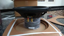
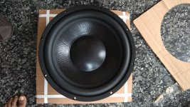
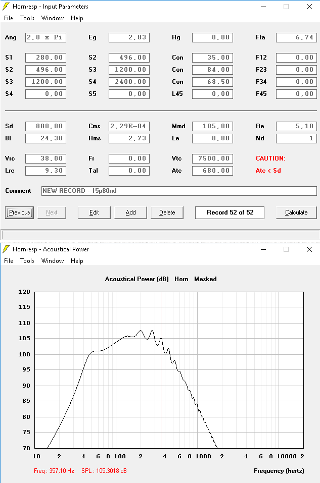
The driver I would want to use is the Beyma 15P80ND.

QTS is only 0.178 and the EBP is 181.

BL is 24.3 so I think it would be a great horn driver
Xmax is 7.5mm.

Xlim is 26mm.

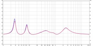
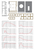
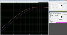
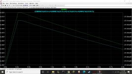
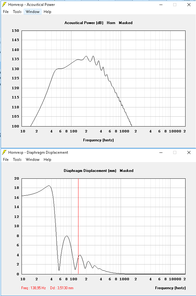
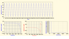
So My first simulation gave this
folded15.png


I think it's actually quite good. The enclosure is only 60cm x 60cm x 70cm
It does 101db at 50Hz. After that it goes down relatively fast.

The driver is rated for 800w aes and 1600w peak.
So when used for continues operating (800w) i get the next simulation.
folded2.png


So that gives 135db of output. Falling to 130db around 50Hz.
It still does 125db at 40Hz ....so a little bit Eq is possible.
Simulating the 15P80ND in a BR enclosure only gets me to 122db at 40Hz....

Looking at the excursion it goes a little over Xmax around 80Hz but it's only 0.5mm so not a big problem.
Even without a Highpass filter the woofer is well within the Xdamage Limit altough I would not do that.


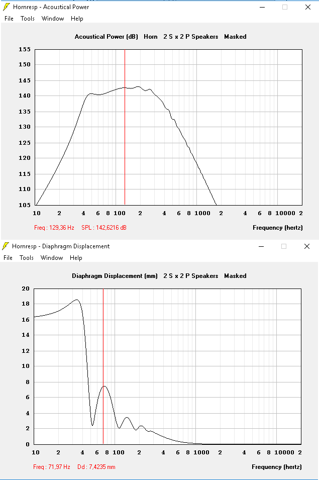
Now if I would use 4 of those boxes stacked together at full power then the simulation changes to this

folded3.png

That is over 140db...
It goes a bit lower also (around 45Hz)
Xmax is also reduced a little bit

You can even push further and use 1600w peak for each driver resulting in 145db... but xmax goes up. Still below Xdamag but a little bit over Xmax so distortion will rise a little bit.

So what do you guys think of this horn design? altough a little bit "outdated". Using a modern speaker I think it could work and still be transportable.
There will be some compression loss at high power but I think it will go very loud. And most of the alround music at small parties will not lose that much extention.

And what abou tthe upper extention? I would like to cross at around 200-250Hz
Looking at the graphs I think it would be possible

Crown CE 1000 Small Caps

This amp has plenty of bipolars in the finals, a reasonably sized PS tranny and good cooling. The two filter caps are small, however. Is the main compromise with this (small?) cost savings in filter capacity the amp's dynamic range - especially bass frequencies?

Internal space is limited so I'm wondering if upping the uf's (to a worthwhile degree) can be accomplished without changing the rectifier diodes. Would I have to increase the capacity approximately fourfold, would that have to be mounted externally and is it worthwhile? The CE 1000 is 21 years old.

The amp is currently used in bridged mode driving a four ohm bass guitar cab with reasonable results for now. My hunch is to upgrade the existing caps using the existing PCB space.

Thanks for your help and opinions.

Advised grounding of cd player

I'm modifying a Philips cd600.
Added another power supply and regulation and lots more.
So since grounding of these players does not include the enclosure (top and bottom) i want to include those, as well as the power inlet.
So what do I do? Connect inlet and enclosure to the PCB ground? Or does one need to connect to the PCB through a resistor/capacitor or some other circuitry? or just a wire? Or do i just connect inlet ground to the enclosure and not include the PCB.....
I did some experiments and could hear quite a difference by just connecting those step by step, but now wondering what is 'correct' or 'advised' way to do this, specially also if other components are needed.

Thanks,
Wouter

FS: AB100 boards

For sale are two pairs of bare PCBs for Nelson Pass AB100 amplifier. The design closely follows that by NP himself, with added mounting holes that comply to diyAudioStore's Universal Mounting Specification.

The price is $25 for one pair of boards (two channels, one board per channel) plus shipping ($5 within continental US, $10 to Canada, $15 elsewhere). Please PM me if interested.

Attached are a photo of an actual board, another of a completed build of one channel on a test heatsink, and a picture with the board's dimensions.

Attachments

  • AB100.png
    AB100.png
    106.7 KB · Views: 423
  • IMG_3168.png
    IMG_3168.png
    585.4 KB · Views: 413
  • IMG_3738.png
    IMG_3738.png
    505 KB · Views: 442

Initial setting of F5 bias--help, please!

All,

I'm firing up my F5 amp modules today for the first time(!).

The Nelson Pass F5 Power Amp article extracted from AUdioXpress, May 08 states, under "Initial Adjustment":

"For each channel you will be adjusting P1 and P2 alternately in order to achieve 0 volts DC at the output and .59 volts across R11 and R12......

"In spite of the thermal compensation in the circuit, you should assume that there will be drift as the heat sink termerature rises, and you will need to readjust the values over the course of an hour or two. Usually it is best to start out bias adjustment low, at maybe 0.4 mV across R11 and R12 until the amp is warmed up a bit....."

I added the bold font, in the extract, above.

Question: Do I really want to initially set the R11 and R12 voltages to 0.4 MILLIVOLTS as the article suggests--or should that be 0.4 VOLTS?

I think I know the answer, but wanted to double-check before I torch my MOSFETs.

Thanks,

Ken

Hello! I'm trying to make stuff!

Hello there!

My name is Greatest Cupcake, or Cupcake, whichever is better for you!
I found this forum by doing a BUNCH of digging around, and mainly
because I have some speakers that I'm trying to make a crossover for in a car!

My knowledge of this stuff is very low. I know speakers and the basics
(V, A, W, Ω. etc), but making a crossover eludes me! I've made a crack at
it, I'm currently trying to figure out where to post it so that people can see
and help me out!

Once I got one built, I'm gonna install it into my car door, test it, and if I like
it I'll make another one and add a sub! I'm excited to see how it sounds!

A bit about myself, I'm currently an Electronics engineering student, I'm
struggling with any job I can get during these hard times,
and I enjoy sitting at my computer longing for things I can't afford. I also do
a lot of headphone modding for personal use (I make pretty much any
headphone I use have a detachable wire). I also also love working with wood!
I'm currently refinishing a table for my Grandma 😀.

I'm happy to be here and glad to meet you all! I look forward to cracking the
vault of knowledge this place holds!

Digital Potentiometer Volume Control

Hello all, new to this forum, hope I’ve posted in the right section.

I'm building a wired Volume Control for my DAC and need some help on what parts/components I will need.

Currently the DAC volume is controlled by a 3 Pin Mechanical 10k Potentiometer (turn knob style).

It’s really simple on how it operates, the Mechanical Potentiometer takes +3.3v and GROUND from the DAC, the Potentiometer position determines on what Voltage is Outputted, this in turn puts the DAC’s Volume UP or DOWN.

Current Mechanical 10k Potentiometer
- INPUT: +3.3v VOLTAGE
- GROUND
- OUTPUT: VARIABLE (up to 3.3v MAX) depending on the current Mechanical Potentiometer position)

yqSLi0Ta8X8UeYNtFp5g6dnZeO_l2AHXdNLX0__Hujw3hzIQiaG52PCG0ju5m9SONzJyz9UfWDcWDnWfW3ffzAQFyIixbuo5ELP2yTscFjMsB6_y3_UDV8TS_s9YGvjyRfinC21F8tLHkUmHg-lvYd8-7HGEZrQKCV3KtwAVo3z2hCgU0VucyXmV2quGj1Omzn-Bu2yHSVkIZsTp6EWpCUFntGBYUvk5RcrDgQypbbXNIMRLWLNV4HZ5GsNZzwyI_A7-i3PekIsJzQqeFYN2FptBIdtBDVwI3TYy3_3v8hdN_jIE7G0sQhsJO8U_XBWDsAazY2EDw417qDmhlnP97cBU5w346w29df-NpEDZU5bg3mXL9HSnAOkgj6m5AnquPNBEjA0YIlBu-jt5v6HaAiVA9JmI4HbIuYvNYM45g4Mhoy32gpzXfs5xmzVSRPnv4LTobV6yNdalBulMHTz9jlhrTlESbYoB1MUymsi7paCBlemABRrAXUDCeZY4AgS3Nj0HbPdz-xMIC2bNx2YQoMs9Zj-LoIdZy2m-nmc1L1AZt0UGv1xAMVcFRJ5suMcWqTtDIzC67k5irszPNJvXjRYLOrVCoMelrHNQgZ3749R92eSQaHOvzg4moBg8Mh9waPUZPAh4ufiiZy5lN39al3P8I0h0w9W-dUL7FxBLXpLkQgxAm6DJQZDpw9U7vg=w289-h552-no


Proposed Digital Potentiometer Control:

- 2 Push To Make Buttons: UP and DOWN.
- INPUT: +3.3v VOLTAGE
- GROUND
- OUTPUT: VARIABLE (up to 3.3v MAX) depending on the Digital Potentiometer position)

If possible I’d like the Volume to adjusted Logarithmically with a Maximum of 32 Steps.

ePmN2JzzYupM9URBe1blXjZGHsCDFcVdD4F6L584HPt5HLFnoDtGPQMxJFHcvKi27bSXH6VD4FKc5HN5Xtq0CCHGn6jXSYoTznCyVF0xwgEykbBoQwMUrK02p_QAmZpfGrXtTfatOpSv076Fk3-GHgBipXlzX7MKxRAPmf_YGxWZMwheo6PsJv7nlJ8kY8oSJ_HDIg64QF3JlvhWhWCYmZ-4ax_t7o41Uu1xEeGyetWw9ufV6IU205FzGODGsDckL7V6zLj3Z65JUtHe0ipgjtatlOWAGuwSMYxehgxwVwFW84EumgYJ5s9Qqa7YOAlpvL50X_e_7iwxWtGj945nvUdTY3DzKa7Vip_fwV5BPlKwUjc6DUBmPdoMUPwOc8CA9asWeagXjUGCFjPMGP8JmHkOK0wFCvZakICjuZDnvMs4qpGoOejjy8Vay1Fv1Jd9l8zyRzWnlcaTzuEOWtjt0f6mnmk5SnvlQdFt_sskr2XBcdc-YtGjdo-wNZkJFRB3ej0B6Qcp24r1vTfBk0b6YNm20CGfBABpa9fhAP9buV12CsMoOVhgDhFYZP-N_K5EqdPyW6prLDJ0ICVqqLPWDLF8MkdMW_gDgJfrDax2Q0L-HsnVgtc27iBQeUI9sy3yFdVe4CLwLkSZVCMSS-GfanrySn1LMy0KtBkYdnMY16ohDn2Q4NWtIpcIla_-eA=w405-h271-no


I don’t need any computer control modules/interfaces etc as this is a stand alone Volume Control so need it to be really simple, hopefully someone can point me in the right direction.

Orion hcca 3000.1dsplx help/parts?

Hello everyone I ended up with a blown orion splx 3k and I am in search of some parts and help to get it back up and running. I have removed all the bad power supply fets and 1 bad rectifier. I'm trying to locate replacement parts as well as some pieces that were lost before I received the amp. I need 2 factory mica isolators as well but I can't find them either. The only part I can locate is the rectifiers. Any help is greatly appreciated. Thank you in advance. I can email or message pics of the fets but not sure how to post them on here. But ill type out the numbers on the fets.

Ixys
Ixfh270n06t3
Korea US1851
S27163

Ixys
Ixfh270n06t3
Korea US1906
S27692

Suitable replacement for 2SA836?

Identified a fault in a hitachi HA-610 with Q703R, which tested good out of circuit but in situ the base voltage was off, which was in turn causing later stages to have incorrect DC voltages too.

The original transistor is 2SA836.

For troubleshooting, I swapped it for a BC558 because I have plenty on hand, and it corrected the fault.

I have enough BC558 (good vintage parts, most of them) that I could replace Q704 and Q703 on both sides with matched pairs, however I am not sure whether this is a suitable replacement, or if I should use a different type to maintain the original performance of the amplifier.

Any advice?Screenshot_20201110_225743~2.jpg

Simulating single pole vs. Transistional Miller Compensation (TMC)

I have been trying to simulate Transitional Miller Compensation (TMC) to see what kind of benefits it might provide before employing it in a circuit. In one circuit, there is only a single Miller capacitor C9=150 pF (C3=0 pF). In the TMC circuit, there are two capacitors and a resistor in the compensation loop: R107=470 ohms, C9=68 pF, C13=470 pF. I have tried all kind of combinations of R107, C9, and C13, and the distortion does not seem to be significantly different at all. In both cases, the distortion seems to be on the order of 0.005% to 0.01%. Practially speaking, there is a peak in the gain around 1 MHz that seems to need to be suppressed in practice to prevent oscillation by setting C3=100 pF so that the distortion increases to 0.02% to 0.03%.


I am performing the simulation at 20 kHz with full power input (equivalent of about 200 W at 8 ohms) and using Fourier analysis to find the magnitude of the harmonics of the 20 kHz primary frequency.


Has anyone simulated this before and been able to get very low distortion? Is there a limitation just due to the crossover distortion anyways, or is there a better way to simulate it? Perhaps I am just running into limitations of open loop bandwidth?

Attachments

  • without-TMC.png
    without-TMC.png
    80.3 KB · Views: 598
  • with-TMC.png
    with-TMC.png
    77.3 KB · Views: 603
  • results-without-TMC.png
    results-without-TMC.png
    81.9 KB · Views: 536
  • results-with-TMC.png
    results-with-TMC.png
    119.4 KB · Views: 534

Bootstrap circuit for the input triode

Generally I see that often less is more. More tubes may be added if there are good reasons, but only then. So I thought that between the passive attenuator and the input stage of the valve amplifier there may be some circuits, filters or what ever. It would be tempting idea to leave out buffer amplifier stages. In that case it would be beneficial if the input impedance of the first amplifier stage was very high. So, it would be reasonable and simple to add a bootstrap circuit for the input triode. But, are there reasons to avoid a bootstrap circuit?

What causes listening "fatigue"?

If I go to an audio store that carries mostly $1,000+ per pair speakers I would expect most to at least be fairly pleasant to listen to. But, at least 9 out of 10 of these (and other) speakers I've heard do not draw me into the music, do not soothe me when I hear them, and, more often than not, are so poor sounding to me that I usually want to turn them off in a mater of minutes.

I don't know if something in me has changed now that I'm old compared to when I was 20-something and before, I loved listening to all kinds of music even on my cheap-o bookshelf speakers. Now, each time I try, it's not pleasant, I end up giving up quickly and turning it off. :bawling:

I still enjoy the sound of live instruments though, and I like watching movies (and listening to the soundtracks while I watch them). I love the sound of a good home theater audio setup and am consistantly impressed by good DTS (or DD) 5.1 sound tracks playbed back through my Onkyo TX-DS787 reciever - it's simply awesome for DVD playback. But, other than being able to play loud and clear, I always feel like something is missing (besides my hearing) when listening to music using it.

Surely, some of the displeasure is because my hearing isn't as good as it used to be, but that's not the only thing.

What do you guys think usually causes "listening fatigue"? :dead: This is a term that I never heard being used 20 years ago, but, I think I've seen it tossed about frequently for the past several years. It seems that speakers have become more fatiguing over recent years, perhaps? Almost as if a flat FR doesn't make our ears happy, it seems, however senseless that may sound...

I just want to say AHHHH..., sit down, relax, and be drawn into music again, for it to be soothing, and pleasant. Will I have to get a crappy pair of two-way paper cone bookshelf speakers and rumage around garage sales to find another old 2 channel tube amp before my ears can be at peace again?

On this and other forums, I read all kinds of gushing and praising of this and that (DIY) speaker - I have got to go to some DIY-fest type event and hear some of these speakers for myself... :xeye:

Counterpoint Electronics/Counterpoint Acoustics/Counterpoint Audio

Attachments

  • counterpoint electronic systems pre-power open top.jpg
    counterpoint electronic systems pre-power open top.jpg
    149.1 KB · Views: 480
  • counterpoint electronic systems pre-power.jpg
    counterpoint electronic systems pre-power.jpg
    90.6 KB · Views: 459
  • counterpoint electronic systems rear poweramp.jpg
    counterpoint electronic systems rear poweramp.jpg
    101.2 KB · Views: 463
  • Counterpoint preamp.jpg
    Counterpoint preamp.jpg
    10.4 KB · Views: 460

An alternative diaphragm coating

So I've recently stumbled across DIY electrostatics, and thought they were very cool. I immediately got to the process of building my own pair of electrostatic headphones, guided by DIY Electrostatic Headphones. – HeadWize Memorial. I've researched several threads on forums such as this one, where there are many variables to consider including spacer height, stator hole size, etc, but the one which varied the most was the diaphragm coating.

According to the forums, there are many things to consider when choosing a coating for the diaphragm, such as adhesion, and resistance. I have seen many different coatings, ranging from dish soap, to soluble vinyl, to vaporized platinum used in Sennheiser's HE 1 Sennheiser Sennheiser HE 1 - - In 1991 we created the best headphones in the world. We called them Orpheus. Now, we have done it again. The uncompromising philosophy remaining, this is Sennheiser HE 1. In otherworldly sound and timeless beauty. Perfectly engineered. Equipped with unique features and state-of-the-art technology.. But one article that helped my understanding of the requirements for a coating is this, What, No Diaphragm Coating Material ???.

The author writes a great explanation on how "Quad approached the problem as a pure electrostatic problem rather than an electrical problem." The diaphragm coating is supposed to maintain a charge rather than conduct, otherwise the diaphragm would move in a non-linear fashion. Conveniently, there is a list of materials which easily get charged, aka the triboelectric series:

An externally hosted image should be here but it was not working when we last tested it.


The author states that that any material above polyester would be suffice, and as it turns out, Quad settled with nylon. And nylon is on the positive side of the list, which makes sense.

I couldn't help but notice mylar was on the list, which happens to be what the diaphragm is made out of. So out of sheer curiosity, I made a transducer with no coating, and applied the bias voltage directly to the mylar. This turned out to be somewhat surprising, because sound came out of it, although it was relatively quiet, and gets unstable at normal volumes. I assumed it made sense because a positive bias charge would indeed charge up nylon, but mylar tends to gain a negative charge instead, which explains the results.

This would be to mylar's disadvantage, because the bias supply outputs a positive high dc voltage. So what if we output a negative bias supply voltage instead? All you would have to do, is reverse the diodes on the voltage multiplier to achieve a negative dc voltage:
pos_neg_multiplier_schematics.jpg

which is what I did, and to my surprise(once again) it actually worked. The bare mylar was able to generate sound, just as if it were positively charged, with a graphite coat. So what is the alternative coating? No coating.

I don't claim to fully understand why this works, only that it worked for me. And since I am making headphones, I'm not sure how this operates on loudspeakers. Feel free to correct me if I misunderstood something.

Weird T/S measurements

I ordered a pair of MCM 55-5670 8 inch woofers the other day. They look good on paper and they meet my design criteria. I tried to shoot some measurements with my DATS V3 but I keep getting this little bump at around 800hz. The impedance curve looks right. But the software considers this little bump the Fs and sometimes gives really high Q numbers and sometimes nothing for Q. Twice I've been able to get some realistic numbers. I played music through them for about 6 hours today and then tried measurements again and got the same results. Has anybody had this happen to them? Do I just need to break them in more? Or is there something wrong with these woofers?

BTL Amplifier DC Speaker Protection (Single Supply)

Hello,
Are here any tallented people willing to share a PCB design for Elliotts' Project 175 (Single Supply BTL Amplifier Speaker Protection)?
Project 175
Due to little interest, Elliott won't sell ready PCBs too soon (that's what he answered).

It seems curious there is so little interest in Class D speaker protection (yes , I know, the chips already have lots of built in protections), while the interest in the amplifiers themselves is quite high.
As I know, UPC1237 is not optimised for BTL configuration, and I really don't trust the chinese boards claiming BTL speaker protection capability.

Thanks.

Crossover sugestions, 3-way Vintage

Ok here is the deal. I got pair of old Philips kit speakers. However, woofer is not original, Seas 25f-ew installed instead.
Midrange is Philips AD5060/sq8
Tweeter is Philips AD0160/T8

Crossover is quite simple, there is nothing for woofer. mid/tweeter crossover is cascade: 36µF/0.6mH+10ohm resistor in parallel/12µF highpass -> midrange (no lowpass) -> 2,2µF -> tweeter.
So crossover frequencies are something like 1500/5000 or so.. sound is pretty good tho.

As the woofer is not original I'm trying to make all new crossovers. I dont quite like the fact that 10 inch woofer is naturally crossed quite high especially in 3-way systems.
I have made MANY two-way speakers but 3-way is much more difficult. As far as I know, AD5060 should be good beetween 700-5000Hz.

What would you do?

Accuphase E-305 transistor selection help

Hi,
I have an Accuphase E-305 with a failed transistor I need to replace. (Q10) I am having trouble matching all the parameters. It is high gain with very low output capacitance. 2SA1376 I have KSA1381 but less than half the gain.

Any suggestions?

2SA1376
Collector-Emitter Voltage: -180 V
Collector-Base Voltage: -200 V
Emitter-Base Voltage: -5 V
Collector Current: -0.1 A
Collector Dissipation - 0.75 W
DC Current Gain (hfe) - 135 to 600
Transition Frequency - 120 MHz

thank you
Evan

Attachments

  • Screen Shot 2020-10-31 at 10.22.42 AM.png
    Screen Shot 2020-10-31 at 10.22.42 AM.png
    866.7 KB · Views: 173
  • Screen Shot 2020-11-08 at 12.44.02 PM.png
    Screen Shot 2020-11-08 at 12.44.02 PM.png
    254.5 KB · Views: 150

Small sub using 2x Dayton DC160-8?

Pls forgive any noob questions, I've never built a speaker, but I am curiously interested in building a small sub for an office/small room setup.

I would appreciate feedback on a low-cost build I've been toying with theoretically. I know there are numerous factors to consider, but I'm playing around with these rather fixed constraints:

  1. Donor plate amp I've acquired: 100w/4ohm with variable highpass 150-40. Unknown brand (model number says SW8030?).
  2. 2x Dayton DC160-8 (because I can get them for near 1/2 price)
  3. Compact
  4. Shoestring budget
  5. General music listening, preferring clean bass over pounding bass and to complement dynamic range for 90db 120Hz bookshelves (Jamo E500)

First of all, does it make sense to use 2x of these drivers (in parallel) to compensate the limited Xmax (~3.5mm)?

I've been playing around a bit with both winisd and vituixCAD, the numbers are a approximate at this point. I have landed on a ported enclosure ~25l, tuned to ~38Hz with F3 ~45Hz. Winisd tells me I am within max excursion at 30w with SPL at 102db

Going to a lower F3 seems to push max excursion beyond limits I think - but I'm not sure how these power levels translate to usable volume...

Enclosure would be down-firing, vented to the front to make it as compact and flexible as possible?

I'm not looking for perfection, but just a decent sub for mainstream music. Is this a project worth pursuing?

Stats copied from VituixCAD:

STATISTICS
f3 44.3 Hz
f6 36.7 Hz
f10 31.3 Hz
Zmin 3.7 Ohm @ 5 Hz
Zmax 28.2 Ohm @ 19.2 Hz
GDmax 13.1 ms @ 34.1 Hz
XmaxC 5.2 mm @ 5 Hz
VmaxR 13.1 m/s @ 31.7 Hz
Pmax 2.1 VA @ 5 Hz
-------------------------------------------------------------
DRIVER: Dayton Audio DC160-8, 2 pcs in parallel
n0 0.52 % Reference efficiency
SPL 89.3 dB/W Sensitivity
USPL 93.1 dB/2.83 Sensitivity
EBP 94.4 Efficiency bandwidth product
Dd 13.1 cm Effective diameter of driver
Vd 85.1 cm^3 Maximum linear volume of displacement
Cas 3.47E-7 m^5/N Acoustic equivalent of Cms
Mas 6.26E1 kg/m^4 Acoustic equivalent of Mms+Mme
Ras 3.82E3 Ns/m^5 Acoustic equivalent of Rms
Rae 3.72E4 Ns/m^5 Acoustic equivalent of Re+Rg
-------------------------------------------------------------
BOX REAR 1: Vb=25.0 l, Ql=15.0
Fb 38.0 Hz System resonance frequency
Cab 1.77E-7 m^5/N Acoustic compliance of air in enclosure
Rab 2.37E2 Ns/m^5 Acoustic resistance due to absorption
Ral 3.55E5 Ns/m^5 Acoustic resistance due to leakage
-------------------------------------------------------------
VENT REAR 1: Dv=4.0 cm, Lv=7.3 cm
Sp 12.7 cm^2 Effective area of port
Map 9.91E1 kg/m^4 Acoustic mass of air in port
Rap 2.37E2 Ns/m^5 Acoustic resistance of port losses

Matched pairs of 2SC4467/2SA1694 or 2SC2578/2SA1103

Hi ! I'm trying to repair my PM-450. The culprit is a 2SC2578 from Sanken. On the Sanken website, it says it's obsolete and lists the 2SC4467 as an alternative.

There are two pairs of 2SC2578 and 2SA1103 on the power stage, so I guess I should replace both pairs with their more recent alternatives, 2SC4467 and 2SA1694, all from the same waffer.

But the thing is, I don't know where to find matched pairs. I contacted my local electronics store that said they could try to find transistor from the same series but there is no certainty they will be matched precisely.

Anybody knows a website where I could get these ?

Speaker case - altering design from kit [newbie]

Hi All

I am planning to build my own set of speakers and am new to the area. I would follow the plans for this speaker:
Loudspeaker shop | Omnes Audio OnePoint10 Kit | DIY

However, I also have a few ideas in mind to make it more aesthetically appealing which would require adding layers of multiplex in certain areas. I would try to keep the interior volume as close to the blueprint as possible. However is there anything to bear in mind if the outer walls become uneven and some with added mass?

3-4" Full Range Desk Monitor Reccomendations

My next build is going to be a small pair of desktop speakers for my wife's home office. I will also be using them for basic gaming (think minecraft) and some streaming. In the next year or so, I plan on augmenting them with a subwoofer once I build her a permanent desk.

Here are my desired specs:
* 4" full range
* The box will be constructed from solid wood (likely Poplar and/or Red Oak), and I'm planning to make it with 100% handtool joinery and glue
* Ported is okay
* max size is 4 L
* I have the TPA3116D2 kit from Jerry's Electronics for the amp.

Here are the drivers I have used previously, I would like to try something new/higher quality:
* Aurasound NS3 - Currently in a 3d printed, ported housing, and lives in the wood shop. Good thump, and gets loud. I would like similar bass if possible.
* Fountek FE85 - Currently in my home office. Sealed, 3d printed enclosure. Was originally part of a 2.1 system, and it shows. One day I plan to add a small sub to my desk, but that comes later.

Here are a few of the drivers I have looked into:
* Dynavox LY302F - seems to have good specs, but I can't seem to find any actual builds on the forums here. Seems to have similar results in WinISD to the NS3.
* MarkAudio CHN-50 - Small and inexpensive. Could have a nice little thump with appropriate porting. Can't find anything on the forums here about this driver.
* Markaudio Pluvia 7 - A nice solid 4" driver. Double the price of the other drivers here. Seems like it would require a much bigger enclosure for decent bass response.

Are there any other drivers that I should take a look at? These will have a fairly close listening position (<1m), and maybe a $40/driver budget. Also, I would be open to using an existing speaker design (like the *onken) if the size is right. I am not expecting amazing low end here, I am more interested in cleaner audio even if it means less thump.

Thanks

Rockford Fosgate T5001bd No sound

Hi, Working on a Rockford Fosgate T5001bd. Called Rockford to check on schematic. Still in production so they won't release it. The amp has sound with the infrasonic switch on. No sound with it off. I suspect it's an op-amp. Not familiar enough with this model to know which op-amps control the infrasonic circuit. Anyone have an idea or schematic close enough to be used to trouble shoot this problem?

Attachments

  • 20201106_120222.jpg
    20201106_120222.jpg
    1 MB · Views: 199

Canadian Monster Yorkville AP6040

Hi Folks;
A 75 lb power landed on my bench in rough shape. It is rated at 1250 Watts per chan into 8 ohms! The protect light is on but chan B is working fine. Chan A has 8 VDC on speaker terminals with no load, about 300 mV with an 8 ohm load connected . There is a momentary buzzing sound coming from the rear of the amp itself, after switching off.
looking for a little guidance before 'ripping' into it. It seems to have (protection?) Triacs across the outputs but if there is a shorted output and the triac is shunting the B+/- from the speaker, would something be smoking now?
Thanks, puzzled Peter in Canada

Attachments

  • DSCN1959.jpg
    DSCN1959.jpg
    982.2 KB · Views: 747

Impulse buy Kef 105

Hi Members,

I bought last week a pair of Kef speakers, type 105.

Type SP1059 is mentioned..but furthermore I might had done a little bit more research before buying them (read: older speaker/ availability of parts)......(hopefully I attached the pictures correctly)

I still need to pick up these (most likely next week) and would be nice if you are able to give me some information:

- Which series are these 105 series 2 ??
- I will listen to these (most likely) next week.. what are the main point of attention (besides not blown up woofers or other strange noises)
- Cross over filter - needs to be recapped ?
- It seems like a relative original speakers, most likely I will try to refurbish them cosmetic - any good (online) stores for parts ?

Much appreciated,

Grtz., Maarten.

Attachments

  • 17e4937e-d477-498c-bb10-68065d990e0a.jpg
    17e4937e-d477-498c-bb10-68065d990e0a.jpg
    41.9 KB · Views: 1,046
  • c3853fa9-f81e-4d54-ba25-89391a52e437.jpg
    c3853fa9-f81e-4d54-ba25-89391a52e437.jpg
    49.8 KB · Views: 665
  • cc108e37-804a-4d6d-8bef-6ccd9855494a.jpg
    cc108e37-804a-4d6d-8bef-6ccd9855494a.jpg
    67.1 KB · Views: 564
  • 94b8799c-623a-46a1-85a2-5db7555009d3,jpg.jpg
    94b8799c-623a-46a1-85a2-5db7555009d3,jpg.jpg
    56.3 KB · Views: 517

Elekit TU-8500 Phono Amp

Elekit TU-8500 Phono Amp
Available in late Feb 2015
Another wonderful design from Mr. Fujita
www.vkmusic.ca/TU-8500.htm


http://youtu.be/wGnKvAtc0Rc TU-8500 internal View


Stock tube: NOS 5965A X 2 (option :12AU7 x 2pcs)
OP-amp: NJM2068DD x 2pcs
INPUT/OUTPUT terminal: Phono IN x 1
LINE IN : 3 (3.5mm stereo jack(LINE3 priority) x 1)
PRE OUT x 1
Power voltage: AC100, 115, 200, 230V
IEC standard, 3P inlet
Rated current: 8W
Dimensions: W252 x H73 D270 mm
Weight: Approx.3.1kg (when assembled, excluding power cord)

[Line amp]
Max output voltage: 22Vrms (1kHz)
Gain: x3.1(9.8dB), x1.15(1.2dB)
Frequency response (-3dB): 2Hz – 70kHz / 2Hz – 280kHz
SN ratio(IHF-A): 122dB / 129dB

[Equalizer amp]
Cartridge: MM(Low) / MC(High) – Select by switching
Max output voltage: 7.4V rms (1kHz)
Gain (1kHz): [MM]37dB / [MC]63dB
SN ratio (IHF-A): [MM]108dB / [MC]88dB
Input resistance: [MM]50kohm / [MC]100ohm

Rectifier IC vs. discrete diodes

Let's say I'm rectifiying a 408-0-408 PT with discrete diodes. With 1kV parts like 1n4007 or 1n5408, I need to double up, because PIV is about 1.14kV. I'm also using a series pair of reverse-biased diodes as a half-wave rectifier for bias supply.

There's a 1.4kV@2A bridge rectifier IC, the DBL209G. I could use that in a FW configuration (i.e., use the positive output for B+ and the negative output to feed the bias supply, and ground the PT CT, with no connection from the bridge to ground).

It's cheap (65 cents), small, and much simpler - takes the place of six discrete diodes. Is there any reason not to use the IC?

https://www.mouser.com/datasheet/2/395/DBL201G_SERIES_J15-1918085.pdf

Need help with baby's first curve tracer

Hey all,

I'm cobbling together a type of curve tracer to test small (~10mA) JFET constant current sources, but I'm seeing what I think is an artifact with the shunt signal amplifier.

The basic idea is to create a voltage supply which varies over a small window (e.g. 10V +/- 0.5V at 1kHz), apply the voltage to the CCS followed by a shunt resistor, then look at the shunt resistor's voltage signal on a scope to see how well the CCS is performing. My initial work on this is detailed here: https://www.diyaudio.com/forums/sol...ed-data-j105-nchannel-jfet-3.html#post6401985

This worked, but the shunt signal was too small, so I added an amplifier to the shunt signal.

The problem is, I am seeing what I think is an artifact, and I'm not sure where it is coming from, so I thought I would turn to the forum for help.

First, here's the sawtooth-like generator circuit:

Attachments

  • Screenshot_2020-11-07_18-19-20.png
    Screenshot_2020-11-07_18-19-20.png
    156.7 KB · Views: 176
  • sawed-off.pdf
    sawed-off.pdf
    35.6 KB · Views: 58

FS: Mini Dissipante 2U + AnTek 2222 + RingNot PSU

FS: Mini Dissipante 2U + AnTek 2222 + RingNot PSU - SOLD

SOLD!


Here for sale is the following:
This was originally the enclosure and power supply for my Modulus-86 build. I have since moved the Mod-86 boards to a smaller case and opted for a SMPS power supply.

If you were ever thinking about building a Modulus-86 or similar amplifier, here is the chassis and power supply already done!

Asking: $125 (USD). I prefer local pickup (western Chicago suburbs). Due to the size and weight, shipping will likely be expensive. But if you're willing to pay for the shipping, I can ship. Domestic only at this time (sorry, can't do international right now).

Thanks!

Attachments

  • chassis_birds_eye_cover_off.jpg
    chassis_birds_eye_cover_off.jpg
    639.3 KB · Views: 349
  • antek_2222_detail.jpg
    antek_2222_detail.jpg
    381.4 KB · Views: 318
  • ring_not_psu_detail.jpg
    ring_not_psu_detail.jpg
    495.2 KB · Views: 308
  • rear_panel_io_detail.jpg
    rear_panel_io_detail.jpg
    375.8 KB · Views: 319
  • front_and_top_cover_on.jpg
    front_and_top_cover_on.jpg
    389.6 KB · Views: 384

Second Stage. Paralleling transistors ok?

Hi folks,

I'm working on another amp and have some decisions to make around the second stage. I could go the MJE340/350 (stand alone or darlington/ compound / cascode) but I like the idea of faster & more linear devices. Finding one that will take a bit of heat is difficult, hence my question; Is it ok to parallel them. In this example it is T9-T12 and I'm thinking 2 each of 2SA1381 & 2SC3503.

Naturally I will match them so I feel it's ok, but have I missed something?

Cheers
Q

Attachments

  • 2nd stage Q.JPG
    2nd stage Q.JPG
    74.5 KB · Views: 823

Transmission line with Dayton SD315A-88

Hello,


I would like to dip my toes in transmission line design. I have a Dayton Audio SD315A-88 I would put in t-line (+-3.8m, 200L in total with a ratio 70L/130L left and right to the speaker). Is this somewhat in the ballpark with your experience?

The sub will be quite big so I want to make the sub downward firing so that I can subtly put it in a corner, paint it the same color of the wall and hope my wife doesn't see it before she hears it 😀


On a serious note: Most t-line's you see are flatpack style (like a big lunchbox with the speaker on the long side). I don't find any downward firing ones. Is there any reason to it? Is downward firing not the way to go?

I like well defined quality bass but I don't seem to like it when there's line-of-sight between the speaker itself and my ears. It feels to direct, pounding my eardrums and less of an ambiance. I find it difficult to describe..I hope you understand what I mean?


Kind regards,
R

SATLIVE and LEVELCHECK by Thomas Neumann

Try SATlive 1.7.10 - very good Software to Measure

www.satlive.audio

Measurment Mic ISMECON EMX 7150 - very Linear and upto 150dB - cost 350euro

index
https://www.facebook.com/pages/emx-7150 ... 7047295436
http://www.emx-7150.isemcon.com/index_htm_files/944.jpg
http://www.isemcon.com/datasheets/iSEMc ... X-7150.pdf

--------------------------------------------------------------------------------------------------------------------------------------------------------------------------------------------------------------------------------------------------------------------------------------------------------------------------------------------------------------------------------------


LEVELCHECK Pegelüberwachung nach DIN 15905-5

www.din15905.de

LEVELCHEK ist für die Live PEgelüberwachung
LevelCheck. See the facts. Messung nach DIN 15905-5

Download
LevelCheck. See the facts.
Projects by fanatics, for fanatics
Get answers and advice for everyone wanting to learn the art of audio.
Join the Community
507,763
Members
7,887,385
Messages

Filter

Forum Statistics

Threads
406,172
Messages
7,887,385
Members
507,763
Latest member
UnisonS6gellert