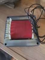
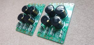
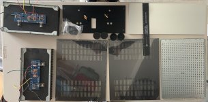
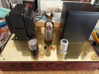
Hifonics VIII Zeus in protect

This amp will COLD power up if you let it sit for an hour un-touched, but as soon as you try to test anything or plug anything in like speakers, RCA, or practically touch anything with the oscope, etc - it drops straight into protect like it's scared.

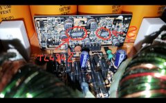
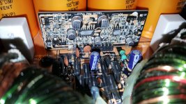
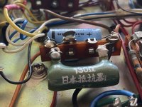
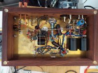
Its funny when it tries to power up, I hear it some stressing through the transformer but twisting it changes nothing. To me it seems like the amp tries to HOT power up about 3 times and then stops as thats what I see it pulling on my bench PS. Currently how it sits it is stuck in protect unless I wait. I tried draining some of the caps but I must not be draining the right one; because then I can probably get it to power up correctly for a few minutes or so. Its using TL594 and a new one for me for latch - which is a 14-pin device with 2B4 HA17324 on it. Looks a little slick too not like a normal IC. Looks custom maybe? Manufactured marking looks like a little camera inside of a circle. Thought it was OnSemi but is not.

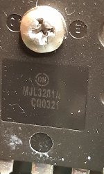
Anyways, I tried removing Q1 which is an A1038 but that didn't change anything. I thought removing it would help produce a power up while disabling some of the protect circuitry but I was wrong.

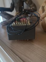
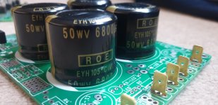
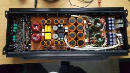
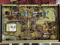
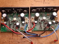
Nothing blown nor shorted on the sides of the board. Board health looks great.

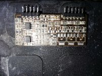
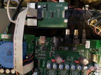
Looks like a newer revision but the revision # is scratched out on the board. This board is not using TIP102/107's tied to the outputs like I've seen in the past on older rev VIII Zeus boards.
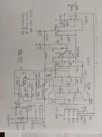
TL594
1: 10.00
2: 4.96
3: 4.86
4: 0.917
5: 1.470
6: 3.545
7: 0.003
8: 13.04
9: 0.002
10: 0.001
11: 13.04
12: 12.52
13: 5
14: 5
15: 11.16
16: 6.25

HA17324
1: 11.08
2: 6.25
3: 11.16
4: 12.33
5: 10.20
6: 6.25
7: 11.57
8: 10.68
9: 6.25
10: 10.68
11: 0.003
12: 10.20
13: 6.25
14: 11.08

These readings are the same with Q1 removed.

During the brief power-ups, I am able to sense decent enough rail voltage. I'm measuring about +-54v, +-30v, and +-17v on the rectifiers, and I believe +-54v on the outputs.

There was no DC on the speaker terminals when the amp was able to cold-power up, but once 'charged' I briefly see about +-1vDC on the terminals.

Is there a part I can pull to stop it flying into protect (So that I can do further troubleshooting) or is this one for Stephen Mantz?

Looking for a good musical sub to blend with full range 6.5"

My brothers system has a pair of audio nirvana 6.5" speakers and he wants a sub added. What is a good sub that will cross up a little higher than most that would be a good match for it? We do not want that car stereo booming crap but rather a seamless blend. I am thinking about adding a mini dsp-hd and running the sub off a low-ish power plate amp. So I don't need a plate amp with cross over built in. I would welcome input from those with a similar situation ( 6.5" full range drivers)

Thanks

Jeff

TDA1540 passive I/U Stage ???

Hello,

I hope there is someone who could help me.
I want to use a older TDA1540 only with a Restistor as the
I/U Stage, without the normaly taken OP-Amp. Has somebody done this bevore ? What Resistor should i take, I tried 100ohm and 330 ohm, but there is a sprankling dirstortion on the less loud passages...

I hope there is someone who could help me.

Best regards from bavaria,
Manfred.

BLACK Holey Basket Coral FE103A(ish) Speakers!

Dave said long ago these existed, but until this pair, I had never seen them! These look to be in great shape. Despite the rarity, same as before: looking for $75 for them. $15 for shipping in CONUS. All others ask.

For the first time ever, I'm planning to actually keep and use the OPTs.

Paul

Attachments

  • Holey 1.jpg
    Holey 1.jpg
    835.5 KB · Views: 181
  • Holey 2.jpg
    Holey 2.jpg
    870.4 KB · Views: 174

Driver Board missing components

Hi Guys

For the life of me I really wonder why people do this when a customer rejects a quote. Not a nice thing to do.

Anyway I have a driver board that had a lot of the transistors missing.

Here are the components that are missing:
1) Q1
2) Q2
3) Q3
4) Q5
5) Q6
6) Q7
7) Q8
8) Q9
9) Q10
10) Q11
11) Q12
12) D3

The board has 2x op amps on it 072 not sure if these are correct.

here is the board:

Attachments

  • IMG_20210416_122244.jpg
    IMG_20210416_122244.jpg
    1 MB · Views: 97

Can you bypass a filter capacitor in a linear power supply circuit?

Hi, I have a 20W class A solid state amplifier with 3 x 10,000uF 63V per channel in its power supply section. It works fine and sounds great but of course it runs hot.

What I'd like to know is has anyone tried using a bypass capacitor in parallel with a filter cap? Is it a good/bad idea? If affirmative:

1) Will it make an audible improvement?
2) I have a 10uF 400V electrolytic and a 0.1uF 800V film cap, which is better as bypass capacitor in this case?
3) If i use the 10uF electrolytic on each of the them I'd be adding 30uF in total per channel, is it better to use just one in parallel with the group?

Thanks and regards.

For sale tube amp transformer new

Transformer for tube amps, preamp projects, with 0-220-240V 400mA and 6,3V 6A.Transformer is about 4kg heavy so shipping cist are not cheap, but if you are from Austria I can send this inside Austria for only 7,90 euro. Al other EU countrys plese ask for shipping costs. Shipping only inside EU. Price would be 50eu plus shipping or best offer.

Attachments

  • IMG_20210328_100736.jpg
    IMG_20210328_100736.jpg
    310.6 KB · Views: 355
  • IMG_20210328_100750.jpg
    IMG_20210328_100750.jpg
    291.5 KB · Views: 355
  • IMG_20210328_100804.jpg
    IMG_20210328_100804.jpg
    312.4 KB · Views: 348

Sunn 200s needs large Cap.

I have a question. I recently took my Sunn 200s to the repair shop as I had replaced the tubes, but they were burning one bright one dim in the power tubes and sounded like a electrical storm of noise. He replaced the biasing pot and got it going again but it is still relatively noisy. I said, "What's that?" He says, "Oh, you want that fixed too?""Yeah. would you play a gig like that?" So he says it's the big coke can sized blue Cap. that is causing that. He said replacement part is not available, but he could put in 2 caps @ half the value of the original one inline and it would be the same. Is this true? or is it going to cause more noise? I got the amp for free, but after the 2nd repair I'll have $460 into it. Is that pricing accurate? Thanks.

Sony CDP-M97, spindle motor not spinning at all

Hello!

I got a 1989 CDP-M97 for free and I'm trying to get it back to life.

It looks ok regarding controls and display. The tray rubber belt had perished and a replacement got it working once again. However, the spindle motor isn't spinning at all.

The sled motor does work (I turned the assembly to displace it just about 2 cm and it reset to center position once powered on) and the laser also tries to focus. I can see the laser dot too.

The spindle motor actually turns if a 5v DC voltage is applied, so I guess this has something to do with its control. I got the service manual and it looks the TA7256P could need replacement, but on the other hand I've never serviced a CD player before so I'm not sure if the laser needs to finish some tests before telling the spindle motor to engage.

Any help/comment is appreciated.

Best regards.
JZ

Cambridge audio a500 blown resistors

I purchased this amp on ebay and after a few days of use I smelt burning plastic and the left channel died. After opening it up I saw that 2 resistors had blown R216 and R214 (I also replaced the surrounding resistors incase damaged). I powered it up and it worked fine it was stable untill I connected it to a my speakers (old b and W 686s), at which point both the same resistors burnt up in a second. Would replacing the sap15s help as I see that on the board that they are the tings connected to these resistors? And advice would be great thanks 🙂

Heat Sinks for Alephs (and Whatever)

I'm thinking about building some Aleph 5 monoblocks using the kk-pcb boards. (I gather that, since these are clearly labeled as clones, they are all right to use.) My question is really a general one: How can I decide how much heatsink I need? I have read the various threads I could find about this, and I take it that I need to know how much power is going through the output devices. Then, if I understand correctly, I can do something like: R = 30 / POWER, where POWER is the total amount of power being dissipated; R will then be the rating I need on the heatsink. So how can I figure out how much power is being dissipated?


For what it's worth, I'm also building an Aleph J and have found some cool-looking heatsinks on the web that would make a very cool case.... So the same question arises there.


Sorry if this is a silly question, but I'm much better at building these things than I am at understanding how they work. I'm a philosopher, not an engineer....

Risk of fakes - very OLD chip amps

Before the knee jerk reaction of “only buy brand new from Mouser”, hear me out. What is your collective experience with getting real vs fake, on old obsolete chip amps that show up on the surplus market from time to time? I’m not talking about the stuff everybody uses, but specifically the 5 to 8 watt 14.4 volt single supply amps designed for old school 1980’s car stereos? I have a buddy just starting out in electronics again after 20+ years, and he just can resist playing with these things - because that’s where he left off. Stuff like the TDA2002, TA7205, BA5406. I fool around with these old parts too, but if I get a bad one it’s a don’t care. So far the only “bad” one I ever got was a BA5406 that I couldn’t get to stop oscillating. Different part numbers show up all the time, including types I’m not familiar with. The available quantities are often so low that you can’t put together a “test” order and expect to get a half dozen next week like I do when I find old TO -3 power transistors to stock up on. I’m not talking about a lot of money to be out of, or anything that would start a fire if it was no good. 12 to 18 volt power supplies. I’m perfectly willing to throw 20 bucks at an experiment and so is my buddy. So far almost all of these parts have been trouble free. I was just wondering about the collective experience with the lower tier stuff that might not have as much “incentive” to fake as say the TDA2050 or 3886.

Speaker driver measurements: 2-4" midrange, full range

Hi all,

Several years ago I measured a bunch of 2-4" cone midrange / 'full-range' drivers and published the results on my website, in a 'Zaph Audio'-style. You can view the measurements and commentary here:
Timothy Feleppa's Pages

I still have all the measurement equipment I used in 2013 and I'm hoping to get back into measuring soon. I plan to add +10dB and -10dB harmonic distortion sweeps in addition to the existing test level otherwise the test methodology won't change.

My interest is still primarily in small drivers with the focus on using them as midranges in passive 3-way systems. Drivers I have acquired and plan to test very soon are as follows:
-Scanspeak D7608/920010 3" dome midrange
-Dayton Audio RS52AN-8 2" dome midrange
-Dayton Audio RS52FN-8 2" dome midrange
-Dayton Audio RS75-4 2" full range
-Aura NS3-193-8A1 3" full range
-Peerless TC5FB00-04 1.5" full range
-Peerless TC5FB00-08 1.5" full range
-Peerless TC5FC00-04 1.5" full range
-Peerless TC5FC07-04 1.5" full range
-Peerless TA6FC00-04 2" full range
-Peerless TA6FD00-04 2" full range
-Peerless TC7FD04-04 2.5" full range
-Peerless 830970 2" full range
-Tang Band W2-748SG 2" full range
-DLS Ultimate U2.5 and UR2.5 2" dome midranges (Morel CDM54 and a version with a sealed rear chamber)
-Tang Band W3-2141 3" full range
-SB Acoustics SB65WBAC25-4 2.5" full range
-HiVi B2S 2" full range

All of the drivers previously tested and the ones listed above have been purchased by myself with funds from my own pocket. I have no affiliation with any audio companies, my day job is not in the audio industry. Up until this point I have been doing this only to satisfy my own curiosity. If there is significant interest in a particular driver and I become interested too, i'll consider purchasing and testing it. Being in Australia shipping is quite killer from USA and Europe so I can often only justify buying a whole bunch of drivers at once, rather than buying just one pair at a time.
I may consider in the future accepting driver donations for testing if there is demand. I will never do a 'paid review' however - my opinion can't be bought and I will always call a spade a spade 🙂

I may also consider doing ~1" tweeters and ~6.5" woofers in the future as I have a bit of a collection of those now too 🙂.

Any feedback is always appreciated. Cheers!
-Tim

Peavey PA-200 Powerup With Dim Bulb Tester and Variac

Hi All,

I am slowly powering up an old Peavey PA-200 in unknown working condition. The boards and connections look ok (no signs of arcing or other damage), so I am slowly bringing up the mains power with a dim bulb tester (DBT) and Variac. I am starting with a 40 watt bulb, and my chain is wall -> Variax -> DBT -> amp. I have a speaker hooked up to the output as well.

Everything seems to be fine until around ~40VAC on the input, at which point there is a "pop" in the speaker and it starts to hum. The bulb is not lit at this point.

Is this expected? Should I keep cranking up the input AC, or is this hum indicative of an issue (bad filter caps)?

Any help is greatly appreciated.

Hearing deteriorating. Packing it all up.

Hi guys.
I spent the last 40yrs collecting and enjoying music and equipment. I am 61yrs now and my hearing has gone downhill because of my employment. I can no longer enjoy my passion so I am selling up.

I had some great years building a sound-proofed room and stocking it with some great hi-fi gear. I've had so much fun with my music but, alas, I must give it up. I am selling my house here in Spain. My kids are grown up & flit the nest. Time for me to find a new chapter without hi-fi. (maybe a small unit). I quite fancy living on a boat for a few years on the river Shannon in Ireland.

I will disappear by the end of April. I am giving all my equipment to a hi-fi dealer here in Spain, for him to sell. If there is interest then I will provide a link. Most of my stuff is Luxman & English from 70s, 80s.. I'm still dusting boxes to see what's inside.

I wish you all the best in seeking your own Nirvana within music. I will miss the comradeship of the hi-fi community. You guys are 'solid' and resolute. Keep doing what you are doing.

I am not ready to put my slippers on. I am merely taking a left turn in my life. A new chapter.

Best wishes, Stephen

Prasi CRC Ideal rectifier psus, part populated

Selling these on as I have gone a different direction and now using Prasi Capmx set up.
I intended to run these as dual mono so one of these boards per channel of chip amp.
Has Roederstien 6800uF 50v caps, faston tabs, and the Mosfets soldered in.

High quality boards as you know from Prasi.

Asking £20 each or £30 if you want the pair. Postage anywhere at cost. Probably less than £5 UK and a little more into Europe. ROW i would have to quote.

Attachments

  • 20210418_072934.jpg
    20210418_072934.jpg
    636.5 KB · Views: 161
  • 20210418_072912.jpg
    20210418_072912.jpg
    809.7 KB · Views: 170
  • 20210418_072959.jpg
    20210418_072959.jpg
    609.7 KB · Views: 146

  • Locked
Email was down for about 18 hours, now restored

Outbound email stopped working just now for about 18 hours due to us hitting our sending limit with our mail host (we had plenty of wiggle room with them but we went beyond even that). This was primarily due to the large number of extra mails sent during the VFET lottery (up to 1,500 unique members in a thread getting lots of updates in all three VFET threads).

The situation has now been resolved, and we'll work out to ensure it doesn't happen again.

HEXFET amp - please help me fix it.

Hi! This is my first post and I’m coming in full speed. Some years ago I’ve build the Giesberts HEXFET amp (elektor). I’m very happy with its performance. I think it has a quite clear sound overall, although I had the usual problems with oscillations, burned HEXFETs and resistors going up in flame! But I was always able to solve my problems. Mostly by replacing components of the output stage, along with some luck 😉

But now I can’t find my way out! A year ago the left channel decided to blow my SEAS speaker. I replaced all the burned up resistors (don’t remember which) along with all the transistors and FETs. I turned it on and Boooom! R27 (I think) was gone. I replaced it and turned it on once again, but nothing! I was stuck with 100mA (regardless the setting of P2) and zero output. I rechecked my PCB connections, but didn’t come across anything suspicious! So in despair, I let it be!

This was until some days ago. I really miss my old amp and I want it working again! So I tried to take a look, once again. It only took me about 10 months to find out that my relay had a fault. So bypassing it I gave it another try and guess what… I have sound! Problem solved. Not quite. It is distorted! But it is alive and with a high levels of amplification, meaning that my HEXFETS are just fine. I’m sure of that because I also tried them on the right channel board and went ok. This is what i see:

1. Amp current stuck at ~100mA (instead of 230mA), regardless adjustments of P2.
2. DC offset just fine ~1mV.
3. D1 and D2 stay on after amp goes off for 15sec. on the right working channel but on the left channel they are turned on for more than 40sec.
4. HEXFET’s are ok since they provide hi level amplification.

I’ve read what egberttheone and Zimo did and I’m willing to give it a try too. Although I doubt their mods will do me any good. My amp has loud distorted sound without burning any of the circuit components. Why the hell can’t I change the 100mA current? Is it a failure of T7? This was a working amp for over a 3 year period with daily usage. I’m ashamed to have it laying down dead.
Anyway my equipment is only a digital millimeter and an analogue current meter at 500mA. I have also been messing up too much with the PCB and lots of the traces are “replaced” by wires. So components are not easy to go in and out. I’m so close but still so far! Sorry for my English and my long post. Just wanted to give you a solid background of my situation. Won’t be checking in for 2 or 3 days cause I’ll be on a trip.

Thank you for your time!

Attachments

  • hexfet.jpg
    hexfet.jpg
    77.6 KB · Views: 3,009

Rearview camera video format

I know this is not exactly an audio question, but close enough...

Does anyone know what kind of video signal the aftermarket rearview cameras put out? Digital, analog, what frequency, what amplitude, etc. I need to troubleshoot a system and I want to know if I can use a scope to look at the signal. I only need to see if I have a reasonable signal, not the quality of the signal. Currently the head unit says No Signal.

Is there someone here who would build a little cabinet for me at a low price?

It would be a little "Karlson style" midrange test box for an 8 inch speaker. (B&C 8PL21)

Construction = 1/2" plywood.

The driver would front mount on its baffle.

The aperture "wings" screw to sturdy 3/4"x3/4" cleats as will have pretty strong input peaks.

It does not have to look "pretty" nor have any finish but should be reasonably square and strong.

I've tried many times over the last year to contact my regular builder but assume he's busy farming.

I live at 25701 if that's help on seeing if shipping is OK

Attachments

  • 8K MIDRANGEFIXED OK.jpg
    8K MIDRANGEFIXED OK.jpg
    362.7 KB · Views: 288

Shall I build a Tubelab SE 300b or Triode Dick´s Little Ceasar?

Hello forum,

after nearly 20 years of building clones on pcbs and point to point, I want solder a circuit containing a 300b end tube.
It´ll run into Tang Band W8-1772 full range speakers and should be a supplement to my Aleph J clone.

After doing intense research I´ve narrowed the schematics down to the Tubelab SE and Triode Dick´s Little Ceasar, cause they are well documented, easy to build and seem to have a lot of followers.

Unfortunately there is only very limited information about the sonic qualities of both amps.

What do you think? Which one will be better? How do they compare to other circuits like the Audio Note Kit One or the F.I. Primer? Would you suggest something else?

Many thanks and all the best

Rene

Triodedick-Little-Ceasar-mk4-Schema.jpg

SoundBlab Transmission Line Speaker Plans

I just bought the plans for the SoundBlab Tang Transmission Line speakers.....

https://soundblab.net/

Ordered all the Xover components and the drivers from Parts Express and a plunge router and bits from Amazon.

Will be building a Router Lift table for my old fixed base router......

Looking forward to see how good a full range speaker can sound....

Switching

While we can build great diy designs, we are stuck with 1957 ugly toggle switches. Even the flood of ‘billet’ on off switch’s are of questionable quality and are almost never 2T2P or are not useful ‘momentary on’ etc...Amazon,Mouser,digi-key seem lost in ugly STSP toggle switch. So someone help I need 2T2P on on push button switch’s, mouser seems to have a single option I think, do we have any more options? (Hopefully avoid Ali)

Maybe I don’t know enough or I’m not looking at the problem from a diy prospective. Of course after talking trash about how ugly they are I am doomed to use toggle switch’s in perpetuity.

FS: diyAudio store 4U chassis with 40mm heatsinks

This is a partially used (or let's say incomplete F5 project) chassis that I ordered around 2012-2013.

It looks similar to current diyAudio Dissipante 4U, with similar dimensions.

The base plate has a few extra holes drilled in it, and I don't think the F5 channels work (but they're not far from it, ask me for details).

Everything seems to be in good shape, no scratches on the important sides, and everything in the picture is included, including an IEC power connector and two RCA input jacks. Original plastic feet as well.

I'll ask $125 + US shipping (48 CONUS please), or a reasonable best offer.

Attachments

  • IMG_6664.jpg
    IMG_6664.jpg
    757.2 KB · Views: 264

What happened to speaker efficiency?

Why is it impossible to find a pair of 2-way 8ohm speakers of (min) 89 dB sensitivity for less than a small fortune and under a metre high (3ft 3"). I have a pair of Tannoy M15 from 1991. They are only 19" x 10" x 8.5" (48 cm h x 5.5cm w x 21.5 cm depth) and have those exact specs. My 2w/ch Bottlehead SET headphone amp gives decent enough volume in my small room.

I want to upgrade my speakers - to build my 'end speakers' - the last pair I'll ever make. They'll need to be efficient so I can use low watt amps (6- 8w). I've decided on a small tower with a small footprint - it will be close to the back wall. Are there any decent kits/designs out there with a minimum sensitivity rating of 89dB- pricing somewhere between an expensive Troels Graven and cheaper 2 Pi Tower speakers (don't fancy using a driver made for a bass guitar amp for my hifi)!!?? I've been on every diy audio site for the past month or so, as well as looking at off the shelf speakers too. There's the Klipsch RP600M, but they have an awful dip in the frequency response in the upper mid/low highs. Plus we all know that we could make a better speaker for the money - but with 96db - how?

I've been down the single driver road (Fostex 208Sigma). Not impressed - huge cab, week bass, would have to build a subwoofer too.

So 2 questions;
1. Why no 'Goldilocks' speakers - decent bass, not huge, not inefficient??? Tannoy managed to produce them 30 years ago, so why not now?

2. Why does sensitivity reduce when a driver is put inside a cabinet? I found a design I like - the WD25t that has the Seas A26RE4 woofer (89 dB) but the finished speaker's sensitivity is 87dB.

My max budget is £1000 total (including all components and wood, paint etc). If you have any answers or suggestions, please leave a comment.
Thanks

Cleaning up Audio With Artificial Intelligence

CLx_xYCUYAIehxI.jpg


38 years ago, Blade Runner predicted we'd be able to enhance images with great accuracy, by 2019

attachment.php


As of 2019, we have numerous ways to enhance images, and some of them work with startling accuracy

Naturally, someone has applied this technology to audio:

Audio Super Resolution

"We train neural networks to impute new time-domain samples in an audio signal; this is similar to the image super-resolution problem, where individual audio samples are analogous to pixels.

For example, in the adjacent figure, we observe the blue audio samples, and we want to "fill-in" the white samples; both are from the same signal (dashed line).

To solve this underdefined problem, we teach our network how a typical recording "sounds like" and ask it to produce a plausible reconstruction."


It would be interesting to see if this technology could be used to resample or upsample old recordings to higher resolution. I know that most people assume that it's impossible to leverage upsampling to extract more detail from a recording. This is logical; you can't retrieve information that isn't there.

But these technologies are different. They take the signal, then use artificial intelligence to make an attempt to interpolate the missing data intelligently.

Check out the linked website; hearing is believing!

Attachments

  • 2020-04-07 18_05_42-Topaz A.I. Gigapixel vs. PS & ON1 (more tests) – Plugs 'N Pixels.jpg
    2020-04-07 18_05_42-Topaz A.I. Gigapixel vs. PS & ON1 (more tests) – Plugs 'N Pixels.jpg
    233 KB · Views: 2,052

Isolator Board for Soekis dam1941 and Raspberry PI

Hi,

made an isolator board for the Soekris DAM1941 and the Raspberry Pi.
It provides isolated I2S and RS232 ports.

Also some Molex Pico-Blade connectors are there to provide connections to a IR receiver, a rotary encoder and a 10pin connector for some GPIOs for later use.

The project is under CC BY-SA 4.0 license. Feel free to make changes and spread it.
The files for KICAD version 5.1.9 are attached.


Parts List (RS-Components):
788-7609 Panasonic OS-CON, SMD Alu Kondensator, Elko radial 100μF ±20%, 16Vdc, Ø 6,3mm, –55 → +105 °C
903-8798 TDK, CGA, SMD MLCC, Vielschicht Keramikkondensator C0G, 100nF ±5% / 50V dc, Gehäuse 1206 (3216M)
823-2053 Silicon Labs Si8651BB-B-IS1, 5 Digital-Isolator, 2,5 kV 9,2 mA dc, SOIC 16-Pin
661-3778 Texas Instruments TLV1117-33IDCYR Positiv Low Drop Spannungsregler, SMD, 3,3 V / 800mA, SOT-223 3+Tab-Pin
807-1066 TE Connectivity CRGH SMD-Widerstand, 100Ω ±1%, Gehäuse 1206 (3216M)
832-3547 Amphenol T821 Leiterplatten-Stiftleiste Rechtwinklig, 12-polig / 2-reihig, Raster 2.54mm, Kabel-Platine,
832-3626 (2x) Amphenol T812 IDC-Steckverbinder Buchse, , 12-polig / 2-reihig, Raster 2.54mm
197-3377 Wurth Elektronik WR-CAB ribbon flat cable Flachbandkabel, 12-adrig AWG28, Raster 1.27mm, Länge 1m
674-2369 ASSMANN WSW Leiterplattenbuchse Gerade 40-polig / 2-reihig, Raster 2.54mm

optional (Connectors for IR-Receiver, Rotary Encoder, GPIO):
319-1092 Molex PicoBlade Leiterplatten-Stiftleiste Rechtwinklig, 3-polig / 1-reihig, Raster 1.25mm, Kabel-Platine,

125-0730 (2x) Molex PicoBlade Kabel-Platine Steckverbinder, 3-polig Buchse / Buchse Raster 1.25mm, 300mm
279-9263 (2x) Molex PicoBlade Leiterplatten-Stiftleiste Gerade, 10-polig / 1-reihig, Raster 1.25mm, Kabel-Platine,
172-0143 Molex Kabel-Platine Steckverbinder, 10-polig Buchse / Buchse Raster 1.25mm, 300mm
708-5092 Vishay TSOP38438 Infrarot-Empfänger, 950Nm 38kHz, max. Bereich 45m


greetz
tonno

Attachments

Old tube amp - do non-electrolytics need replacement?

I picked up this absolutely pristine Lafayette LA-224B integrated amplifier. It's a 15W push pull from the mid-60s.

It's apparently in fully working order, but I assume the electrolytics need replacement. However, what about the non-polarized caps? They don't look like the old style paper caps -- can I leave them be?

I would prefer to disturb the innards as little as possible, but I don't want to blow my OT either..

Aw, just look at that interior! Isn't is beautiful? Even my wife loved it! 🙂

Attachments

  • DDA056CB-DC8D-4FF3-A14F-3C0DCCCEBC70.jpeg
    DDA056CB-DC8D-4FF3-A14F-3C0DCCCEBC70.jpeg
    439.3 KB · Views: 594
  • 5565669E-CAA9-4412-9CAF-A6D5D8E3E77C.jpeg
    5565669E-CAA9-4412-9CAF-A6D5D8E3E77C.jpeg
    388.6 KB · Views: 593
  • 66B6F4B0-F82B-465E-A646-C6D5DA092E4F.jpeg
    66B6F4B0-F82B-465E-A646-C6D5DA092E4F.jpeg
    547.9 KB · Views: 591

NAD C315BEE Power Supply and Standby Consumption

I recently picked up a broken NAD C315BEE which just needs a fairly straightforward cap replacement. But as others have noted the standby power on this integrated amp is fairly outrageous at 20W. I'm trying to understand where this comes from.

The transformer has three secondaries. An 8VAC winding is rectified and regulated to 5V for the microcontroller circuit. This rail is always on but it is low power.

There is a 25VAC secondary winding which is rectified and then regulated to produce the +/-17V rails. This regulator is turned off by the microcontroller when in standby.

There is a 35VAC secondary winding which is rectified and filtered to produce the +/- 45V rails. These rails are ON even in standby and the power amp circuit output transistor bias is probably drawing the current.

However, the between the 25VAC bridge rectifier and the 35VAC bridge rectifier there are two light bulbs (!). Are these part of some power boost circuit? It looks like even in standby these bulbs have ~10VDC across them. Is this really the source of the standby power draw?

Attachments

  • C315BEE_mainpower.jpg
    C315BEE_mainpower.jpg
    89.4 KB · Views: 279
  • C315BEE_powerboard.jpg
    C315BEE_powerboard.jpg
    96.7 KB · Views: 257

  • Locked
speaker cable myths and facts

Reading up on this and it seems there is plenty of what some of you call 'snake oil'.

It seems low resistance is the most important criteria. Good quality 2.5mm thick cable, without silver plate looks to do the job.. The way some cables are woven is interesting and also the insulation used, but I have no idea if this is worth paying the extra money for.

For my speaker build I am looking at a few options including Shark cable which is incredibly cheap. Also considering Chord Carnival Silver Screen if it really is worth paying extra for. Wd be interested in your views and what you use in your builds whether budget or high end.

Burn capacitor icepower 50asx2se

Hello! Got a dead Teac amp from a friend too look at and after taking out the icepower 50asx2se module it uses I saw that a capicitor placed right next to the rectifier had burnt up. The module is totaly dead so I would asume that the capacitor also tore of a trace from the rectifier onward but I cant find any schematics or pcb layout (and i dont count on them beeing public).

Has anybody any pointers on how to go about fixing this by maybe soldering a jumper instead of the trace that would be much appritiated. I do understand I’ts a long shot and that I dont supply that much information.

IMG 2305 - Forumbilder

Its the one marked c201 down to the left

IMG 2306 2 - Forumbilder

Recapped Jamo J-121 (1979) - further improvements?

Hi everyone

I own a set of Jamo J-121 studio monitors which my dad bought back in the early 80's. I have replaced the electrolytic capacitors with Jantzen Standard Z-cap MKP capacitors in the crossover filter, which gave a significant improvement in the mid and high range (only one speaker so far to compare with). When listening now, the old speaker makes the music sound muffled as if it's in another room, while the restored one is a lot clearer and easier to distinguish voices and instruments, so that's great!

However, the lower frequencies <200 Hz still seem a bit off. I lack proper measurement apparatus, so for now I have to resort to my ears, music, and a tone generator.


Basically if I slowly sweep a sine wave from around 200 Hz and down, there are significant drops at specific frequencies, especially around ~75 Hz, ~63 Hz and ~123 Hz (as my memory serves, I can try and get more accurate "measurements" if needed). At some of these frequencies the volume goes way down, and is higher again once I change the frequency a bit, usually within 1 Hz or so. It also happened before the restoration but at different frequencies, ditto for the other speaker still with old caps.

Is this just a property of the speaker, or do you think I can improve this somehow? The amplifier is a Yamaha RX-465 made for sorround systems, not exactly audiophile but I imagine good enough. The fact that the frequency drops are different depending on speaker/capacitors makes me think the problem is with the speaker itself and not the amplifier.


I have not been able to find the crossover diagram anywhere, if anyone has it it would be greatly appreciated. I hope to drawn my own when I find time, but as I don't have the coil values it might be of limited use.


Questions
1: There's a flat blue/red component in parallel with the crossover resistors. I suspect a thermistor for tweeter protection. Should I replace it?
2: There are overprotection bulbs/LEDs for mid and hi-range. Do they affect the sound?
3: Could improved damping material change the low volumes so significantly? Currently it seems to just be a bunch of old wool (smells like hair when burnt)
4: Other things worth considering in old speakers?


Thanks!

Attachments

  • IMG_20210130_221918.jpg
    IMG_20210130_221918.jpg
    760.8 KB · Views: 464
  • IMG_20210224_105108.jpg
    IMG_20210224_105108.jpg
    940.2 KB · Views: 443
  • IMG_20210224_093547.jpg
    IMG_20210224_093547.jpg
    669.3 KB · Views: 394
  • IMG_20210224_085039.jpg
    IMG_20210224_085039.jpg
    963.2 KB · Views: 381

freeDSP-aurora

If people are interested I plan to produce some freeDSP-aurora in the near future. I just ordered a short run of FreeDSP CLASSIC SMD A/B for my own interest but have extra. If all goes well, my plan is more ambitious. To order a short run of freeDSP-aurora. I would be happy to sell the extras, as it seems an awesome board and I am sure people can put my extras to good use.

Alex

Thoughts on DSP multiamp/attenuator setup?

I'm looking at my options for DSP crossovers, and the DBX Driverack Venu360 seems my strongest option.

DriveRack VENU360 | dbx Professional Audio

The problem with that option is that because it's for a triamp setup, and I'm not running a mixer and matching levels etc, I need a volume control post-unit. Pre-unit would lead to low input levels and lead to noisy/truncated performance.

Right now I'm leaning towards this minimalist solution-

Overview

Combined with the breakout cables needed, that puts me at around $1500 all-in- not a piddling investment but having a good volume control and full DSP with either line-level analog or AES/EBU inputs will be extremely flexible and ensure that I'm not feeding the driverack with low-level signals that will underperform when I'm using the analog input.

I don't really want to build a 6ch volume control using premium goodies, or turn more than one knob, so the SPL Volume 8 seems to be a solid choice (knowing that it's single-ended on the potentiometer).

Any thoughts? Anyone found a solid 6ch balanced volume control option besides this? Is there a $1500 DSP I'm missing that would do stereo 3 ways, well, and not require the additional box? One alternative is analog XOs, but I like the power and flex that the Venu affords me for other uses besides this project.

R channel autodetection when connected to speaker

Hello all,

I would like to build an amp (based on the TPA3220), which could switch between Mono and Stereo automatically when a second speaker is connected.

I know you can accomplish this on devices with Jack outputs (a L/Mono channel and a R channel) , thanks to switched jacks on the R socket which will allow switching to stereo when a jack is plugged in.

Basically, I would like to do the exact same thing but instead of connecting jacks, I would like my amp to output mono when only one speaker is connected, and Stereo when you connect the + and - copper cables of a right speaker.

Do you know if this is possible ? Do I need a particular type of connector, or do you have any ideas to accomplish this that I might not have thought of ?

Thanks a lot in advance !

My new stats, model #4

Hi,

I almost finished my new electrostatic panels. Thanks to the help of several people at this forum I managed to get a good result. (I'm not sure what exaclty is good, but they seem to look and sound good to my own taste)

It took about eight months to (almost) finish them, 150 - 200 hours (rough guess). Especially the wood joints took lots of time.

I will post measurement pics in future. Unlike model #3, which has been in use for the last 3 years, this model has a resonance damping screen. The severe resonance of model #3 is reduced by about 8 dB. I didn't try the most difficult bass-intense cd I own, but all music that previously caused problems (heavy vibrations / resonance) in model #3 seem to play well in model #4!

At first I thought the mesh impaired mid / high sound quality, but after some initial listening tests I think the new model sounds better than the previous model. (tighter lf and because of different segmentation network better hf)

Here is a small selection of photographs I took during the building process. I hope that soon, when I have more time, I can add new photographs and measurements.

The panels are made of birch-multiplex, 18mm thick, outer dimensions are 68x200 cm.

Edit: I changed the externally hosted images with uploaded attachements in the posts below.

n00b here: Tell me why my build isn't as loud as I expected please?

I tried taking this amp 4 x 100W Class D Bluetooth Audio Amplifier Board - TSA8498
Powering it with this battery KLUOSI 10S6P 36V 19.2Ah for LG18650MH1 1000W with 30A BMS 36V Lithium Battery Pack for Ebike Electric Car Bicycle Motor Scooter|Battery Packs| - AliExpress
And using it to run 4x cheap Walmart 6x9 Scosche speakers Scosche HD Speakers for Cars 6x9" Set | Walmart Canada
Enclosed in speaker boxes that are 21x15x12 plywood containing baffling. Imgur: The magic of the Internet
Would you expect that these components would be right for each other or did I **** up?

I've been told that the shape is wrong, that they would be louder if they were more wedge shaped.
I've been told that the gauge of the wire from the battery to the amp is too small. It starts at 14 but then I dropped it unknowingly. The amp starts cutting out at maximum volume, possibly because it cannot draw enough power.

If I change these 2 things and it doesn't make it loud enough I'll probably take the components and put them into a suitcase to make something more portable to suit the lower than expected volume, but I still want a -really- loud battery powered sound system.

External USB DIY DAC - Questions Please

Hi - my first post, so please be gentle 🙂


I recently acquired an External USB DAC - it is one of those DIY Kits, the link is here . The kit was built by the seller who then sold me the completed DAC. It is the "Gold Bundle 2" Kit, with the Amanero Combo384 USB Interface Card. It's the top-end of these DACs as sold from China and to be fair the sounds I'm getting are really superb. It's based around the Sabre ES9038Pro Dac (8 channels split into 2x4channels in parallel to produce a stereo output.


The seller, whilst knowing his stuff (I think) about the parts making up this DAC, he really had no extensive experience with it as my questions fell on deaf ears mainly, leaving me to find out what it was capable of myself. This I have done, within my Setup. I won't go into the full details but I've established its capability with my DSD files - Using UAPP (USB Audio Player Pro) I get up to DSD128 and with Windows (with AISO drivers), up to DSD512 - all of which are to spec. I believe I am also getting up to 32-bit/384Khz flac files playing as they should do too, but have still to complete my tests.


I am feeding the DAC into my intergrated Receiver a Yamaha RX-A1070, via the DAC's RCA outputs. My Yamaha uses a Sabre9006 dac. I set my receiver to "Pure Direct" and the results have really been astonishing - far far better than playing these files using the Yamaha alone.


OK - so I now want to try to setup this same USB DAC with a Vintage Sugden A48 mkII amp. Reason? Well I don't want to mess with my Yamaha, which has been set up for Movie playback - using a sub and my main speakers set (in the Yammy) to play the bass through this sub. Pure Direct knocks out my sub and so unless I elect to play with Pure Direct Off and utilise my sub, playback completely lacks bass.


What I want to do is get an AMP switch which will allow me to switch my speakers to playback from my Yamaha or the Sugden. This will determine which is better.


Questions: -


  • What do you think about playing an External DAC through a vintage Amp?


  • Would it be possible to upgrade the Amanero Combo384 card to one which would allow moreflexibility - ie; so I could get up to DSD512 using UAPP (on an Android Tablet) without being forced to go on to Windows? If so could you point me to one please?

  • I'd like to experiment with Tidal streaming - my DAC isn't "MQA Certified", so at the moment I don't get the second "unfold" with MQA (Master) files, so am restricted to 24-bit/96Khz playback and not 24-bit/192Khz. Is this down to the DAC or the Amanero USB Interface card?


Thanks for reading, if you've got this far - I look forward to any help 🙂

Thanks

GB: Fo-Felix EMI Filter for AC mains 120/230v; By Folsom

Hey everybody!

So over the years people have asked about the old version, made by someone else.

It's probably time for an updated one. This one is a bit different. You may notice it does not have following capacitors after the choke. I have tried both ways, and my preference is strongly without the following X2 capacitors. Also the capacitors prior to the choke are not varied in size because overall capacitance is more important - and they won't randomly resonate with each other.

The other major change is the addition of bypass resistors for the chokes. These don't ruin the filtration, but they do a good job of quieting the chokes that can get excited by different combinations of things on the mains.

Higher-Res image
Fo_Felix_public_previewcrop3.png


Here's how it is different in settling time from the original.
Fo_felix_vs_felix.png


Here's a comparison between resonances.
Fo_felix_vs_felix_resonance.png


*2oz copper PCB (1oz is standard)
*Weco 983ZD terminals, copper alloy and can accept 2 wires for daisy chain (even of different sizes, 12-20ga). These are also safer, particularly if you use solid core wire that otherwise likes to make cold solder joints you can't see.
*X2 rated capacitors for safety, 4x 0.47uf. They are alternated for CFC (capacitor field cancellation).
*Discharge resistor for X2 capacitors
*Coilcraft Comoco choke w/fuse or Bourns 8120/8121-RC choke w/o fuse & 15/16A max sockets
*Fuse clips are beryllium copper (good for 30A)
*120/230v operation (parts & pcb)
*Mounting holes are sized to work nicely with M3 screws and standoff kits
*Size: 2.25x4.25in

The Weco 983ZD are preferred terminals, but not always available as individual sale. For this reason I'm going to include them in the price of PCB, so that I can meet min order requirements for them and save everyone the shipping.

Price: $13ea ($9 per filter board same as original, $2 per Weco, 2 needed per board)
Shipping: $8 US, priority USPS box, $15 international padded envelope

Need 32 filter board commitments to order.

AmpUtator 2
C37 2
torb 3
wushuliu 1
KaffiMann 3
drkingweeb 2
limits 3
ckwong99 4
ericimage2 5
Mcluxun 4
wcwc 5
vinylvalet 4
dhsettim 4
bvtrinh 6
shattered_dream 3

Full Range ASsisTed with woofer: please re-direct me

Sorry, i am new here (ie read a lot here, but never posted). Kindly point me towards an existing thread if there is.

I am considering to build a 'Full Range ASsisTed w woofer' loudspeaker.

Sofar i have looked at Visaton B200 and Fostex Fe166 for anything upwards from 200-500Hz.
I would appreciate inputs on matching it with a 8" or 12" woofer and any guidance on X-filter, if needed at all.

I like transparent sound: not veiled nor boomy with nicely textured sound.
I am using Luxman amps from the 70s.

My living room doesnt support 'open baffle,' but the build should not be overly complicated (no backloaded horns etc).

Any guidance/advice? Many thanks!!

BOSE Studiocraft 150 1979 year repair. Worth it?!

Hi guys!
My friend found this beauty in the trash.
photo-2021-04-16-21-54-32 — ImgBB
It looks ok, but the woofer damaged. I guess I also need to replace capacitors due to the past time. I checked the dimensions and the volume is about 51 liters. I'm gonna buy some 6'' 8 Ohm woofers and replace the old ones. I'm not sure which exactly woofer I need to use. But I guess I can use some which people usually put to 50 liters cabinets with phase investors.
What do you guys think? Should I spend around 100 (200??) Euro to repair these vintage speakers?
PS I believe that we can give a second life to our old hi-fi friends.
250 — ImgBB

Measuring low distortion levels with a sound card

I am starting this thread to discuss the techniques of measuring low distortion levels, say, 0.000 010% (10u%, -140dB) with inexpensive equipment such as a sound card.

The problem of measuring such low distortion levels came up in connection with developing an audio power amplifier with the loop gain of 100dB@20kHz and with the correspondingly low distortion levels even at the high end of the audio spectrum.

What I don't want to discuss is choosing (or making) a better sound card or a low distortion oscillator. These topics are very interesting but are being discussed in a number of other threads which I don't want to duplicate. Thank you for keeping these out of this thread. Having said this, I can confirm that the Linear Technology AN-67 low distortion oscillator built on PCBs from diyAudio member Frex works very well indeed.

Instead, I want to focus on the problems that arise when easily available equipment is used for assessing the distortion performance of highly linear amplifiers and on the way to address those problems.

So far, several topics are emerging:
  • Properly conditioning the DAC output signal and the ADC input signal
  • Using (passive) filters to filter out the distortion of the DAC and to remove the fundamental from the ADC input
  • Subtracting the scaled output signal from phase corrected input in either analog or digital domain
  • Increasing the noise gain of the device-under-test to increase distortion to a measurable level and estimating from it the distortion under normal conditions
  • Correcting nonlinearities of the DAC and ADC in the digital domain (the work of phofman)

FS: SymAsym 5.3 amplifier boards

For sale a pair of SymAsym 5.3 boards cailbrated and in perfect working order.
High quality parts and On Semi genuine power transistors.
You must only add your favourite input capacitor.
They sound wonderful.
Symasym 5.3 Amplifier Sound Best - Electronic Circuit
50euro plus shipping and Paypal fees.
Regards
Guglielmo
Italy

Attachments

  • 20210413_214756.jpg
    20210413_214756.jpg
    886.7 KB · Views: 269
  • 20210413_214940.jpg
    20210413_214940.jpg
    413.4 KB · Views: 223

Another resistance port cardioid woofer project

I'm trying to make a resistive port cardioid woofer similar to a D&D 8c. The frequency response of the woofer will be limited to 150-400Hz. There will be a rear facing subwoofer operating below and mid-range horn above. I'm using a Hypex DLCP digital crossover and N-core amps.

I've read the many relevant threads here and have built and tested one cabinet. I used a Beyma 12BR70 woofer (it's what I had). The port area is 40% of the driver SD and I used Melamine foam and Acoustistuff to fill the cabinet. So far I've reached a 12dB front to back difference. With EQ to boost below 150Hz it doesn't look to bad.

To get more attenuation of the rearward wave do I need more output from the vents or less? Or, do I need to slowdown (delay) the sound going out of the vents with a different ratio of foam/stuffing?

I'm going to build a second test cabinet tomorrow with a larger port volume and with the ports located closer to the back wall of the cabinet. I'll post the results.

The attached ground plane measurements were taken at 0 and 180 degrees with the mic 2M from the box.

Attachments

  • Resistance Box Ground Plane measurement.jpg
    Resistance Box Ground Plane measurement.jpg
    101 KB · Views: 154
  • KIMG0036.JPG
    KIMG0036.JPG
    197 KB · Views: 168
  • KIMG0037.JPG
    KIMG0037.JPG
    186.5 KB · Views: 157

Parasound Zamp 120Hz hum

I recently acquired a Parasound Zamp V1 used, and it has a constant loud hum at what sounds like 120 Hz to me. The hum is in both channels and is there even when only a speaker(s) on either or both channels is connected in addition to AC power (no input is required for the hum). The hum is reduced when I connect an input via the pre-out on my NAD C372 (which I've never had this issue through and still don't using its amplifier stage instead of the Zamp), and I can increase/decrease the volume of the hum by adjusting the level for each channel with the knob on the back of the unit. I tried plugging it in in a totally different room that is on a different circuit as well, but that did not make any difference.

I noticed that immediately when I plug the amp in with speakers connected, the hum starts quiet and then gets louder over the course of a few seconds -- this leads me to wonder if this might be caused by bad capacitors since this is about the same time period that, based on labs in the physics class I had a few years ago, a larger capacitor seems to take to reach capacity/equilibrium.

Any thoughts on how I could fix this? Does my theory about the caps make sense, or are there any other ideas anyone has?

Thanks!

Sound system for electric trike

View attachment 762647Hello, I am attempting to build a sound system for my electric trike “Triguar”. The trike has a 1200w 48v motor powered by a 48v 30ah lithium battery located under the seat. I would like to incorporate the speakers into the frame of the bike, possibly where the gas tank would be on a motorcycle, wondering what size speakers would work best and if I would need build an enclosure to fit inside fake gas tank. Also wanted to possibly add a sub maybe as a back rest for the second passenger. Was looking at class D amps and wondering if I could use a 48v amp or if I should go 24v with a regulator? I already am running a 12v regulator for some led lights. Also wondering if I should use my 48v battery or have a second power source. Budget is around $100-$200. Here are some pics of the trike so far. Thank Jesus you in advance for your help 🙂

James

Attachments

  • 2E441842-2B80-440E-85A5-49AE7C36FAA9.jpeg
    2E441842-2B80-440E-85A5-49AE7C36FAA9.jpeg
    285.5 KB · Views: 288
  • 791C22E6-409F-4D09-9D79-5716331C5687.jpeg
    791C22E6-409F-4D09-9D79-5716331C5687.jpeg
    319 KB · Views: 276
  • D4BE7FCB-2A0A-4952-AB41-BC3DA6AC3D09.jpeg
    D4BE7FCB-2A0A-4952-AB41-BC3DA6AC3D09.jpeg
    464.8 KB · Views: 270
  • DF35D508-7A58-4BE0-9C92-580D91A1ABD3.jpeg
    DF35D508-7A58-4BE0-9C92-580D91A1ABD3.jpeg
    369.6 KB · Views: 262
  • 5EFB2A73-A04B-49AA-809A-945B7979DA65.jpeg
    5EFB2A73-A04B-49AA-809A-945B7979DA65.jpeg
    848.9 KB · Views: 268

Selecting Output Transformer Impedance (for use with a range of speakers)

I'm getting ready to order the output transformers for my impending SSE build. I've opted for larger Edcor transformers (the CXSE25-5K) but I have to choose an output impedance option. I checked with Edcor to see if they can make one with multiple taps, but they cannot.
So I must choose one impedance.
The trick is, I'm not sure which speakers I'll be using with this amp. I tend to swap out speakers fairly regularly as my collection fluctuates, so the speaker choice is liable to change over time.
That makes it tricky to choose an output impedance that will be suitable for multiple speaker types.
If I understand correctly, a 4 ohm tap is the only option if I want to drive speakers with 4, 8 or 16 ohm impedance, but I'm not too clear on this.
So I seek input and advice.

Eico HF-60 monoblocks on custmer chassis

Hi,
Recently I acquire a beautiful pair of unfinished Ecio HF-60 project from a forum member, I want to share the information with my success to build this project, any opinion are welcome.
I had completed build one unit. I do some changed on the circuit as below
1. Add CCS on the long tail pair instead of the 18K resistor.
2. Add voltage regulator for driver stage instead of the 15K.
3. Removed the EF86 cathode 50 uf cap to reduced some gain.
4. Used solid state rectifier for B+ instead of GZ34 tube. B+ was 40 volt
higher, the output was increased to around 70 watt at clip point.
5. Add dynamic bias control and set idle current at 40ma from 65ma.
6. Add a 0.5A fuse at B+ to output transformer.
7. Add a thermistor on the power transform primary side.

Attachments

  • EICO 6.jpg
    EICO 6.jpg
    113 KB · Views: 138
  • EICO 3.jpg
    EICO 3.jpg
    177.6 KB · Views: 137
  • EICO 4.jpg
    EICO 4.jpg
    111.3 KB · Views: 132

Tube Rectifier: What and How?

Just ordered my SSE PCB, and I'm filling online carts with parts now. I've come to the FRED diodes, and in my research trying to figure out what the heck a FRED is, I see that there's also the option to use a tube rectifier.
Well I'm a total NOOB, and I don't know really know what a tube rectifier is. But I get the impression it's better than the solid state options.
Is that correct? Is a tube rectifier the way to go?
If so, how do I implement it? What do I need to buy for it? Where does it go?
Should I just stick with solid state? If so, what's the current DigiKey part number for those FRED thingies?
I'm floundering here, people. I need a life preserver. Any help would be most appreciated.
Projects by fanatics, for fanatics
Get answers and advice for everyone wanting to learn the art of audio.
Join the Community
507,766
Members
7,887,636
Messages

Filter

Forum Statistics

Threads
406,190
Messages
7,887,636
Members
507,766
Latest member
Coreque