300b socket replacement

Hello,
I recently replaced a damaged ceramic socket for a 300b. The original sockets would only allow the tube to fit if oriented correctly. Two large pin sockets and two small, no way to install wrong. The replacement sockets will allow for incorrect installation of the tube if I’m not careful. So what did I get some crappy sockets or what? Just curious what others have to say
Thanks

Group Buy: Linear Systems LSK389 / LSK170 JFETs (i.e. Toshiba 2sk389/2sk170 subs)

well, well, well... I just got off the phone with my local distributor for Linear Systems parts and would like to see if there is any interest in these parts.

The LSK389 is a drop-in replacement for those pesky Toshiba parts, and reported by some to have better specs even than the original. Here's a datasheet:

http://www.linearsystems.com/datasheets/LSK389.pdf

available in the usual Idss flavors, but with different names.

Also, for your viewing pleasure is the now out of production single version of the above. Here's a datasheet:

http://www.linearsystems.com/datasheets/LSK170.pdf

The distributor says they might be willing to mix and match Idss grades for us DIYers, and the order target is 100 pieces of the LSK389 and 100 pieces of the LSK170. So, if you're interested please state your Idss preference.

Now for prices (assuming quantity 100):

LSK389 (TO-71 metal can):
"A" $6.08
"B" $5.87
"C" $5.59

LSK170 (TO-92)
"A" $1.13
"B" $0.95
"C" $0.80

There needs to be another 8.25% sales tax added to the above part cost and shipping is free as they're located in my backyard (almost literally).

Rules for the group buy will be very similar to what I did for the ROE MKP1837 group buy(s) and will be posted later on. I may instantiate a minimum order if I so fancy one as these group buys are lots of work. This will be easier than 6,000 little blue boxes, but still....

Shipping to you will probably be $2 in the US and $4 internationally, depending on quantity. I will only accept PayPal with a 3% charge for US and 4% charge for International. Upfront, you'll be responsible for the number of parts and the PayPal fees and I will bill you later for actual shipping and any other charges that might have cropped up due to mis-estimation (that's not a word, is it...).

Next price break is at 1000, which may be feasible if the heavy rollers step in 🙂 🙂

So, have at it!

Problem with DAC Audiomeca Ambrosia

Good afternoon.
There is a DAC Audiomeca Ambrosia.
The problem is as follows: when connecting the RCD (Rega Jupiter) via any of the 2 inputs of the Coaxial S/PDIF, and selecting the corresponding input by the input selector, the LOCK indicator, notifying, as far as I understand, about the normal connection, does not light up. At the same time, a continuous crackling is heard. Both devices are turned on. There is no way to check the operability using other types of inputs (BNC).

If there are owners of this DAC, tell me which cable (coaxial), how many ohms you use. I met information, that its coaxial input is designed for 100 ohms. Is correct?

I would be grateful for any help.

Odds / ends / deals.

$120/pair. 2010 era pair of lighter cone Betsy. These are slightly / lightly used, but if you’re matching an older era Betsy, this is the last pair I’ll be offering.
$60/single. 2015 BetsyK.
$400 almost new pair of Caintuck OB.

$20/each 2kV 10uF US mad vintage cap. 2 avail.
$10/each 2kV 4uF GE. 2 available
$100/pair Altec 1600V tube transformers.

$220/pair. Fostex D232. Almost NIB. 1 pair available.
$250/single 1 Altec 802 converted to FC by a gent in Italy. Never tested.
$40/pair Emilar 175, bad diaphragms.

I’ll post some pictures, more to come.

Vacuum Tube SPICE Models In Fusion360 Assistance

Hello,

I have been working to create SPICE testable tube amplifier schematics but am having a HELL of a time getting it going!
If I'm not mistaken, I have everything connected properly and built to decent enough standards. I built the 'symbol' as I was unable to find any as well as the 'footprint' for the same reason. I will attach a zip of photos of the issues I'm experiencing and what I've done as well as the datasheet I am currently using. Everything is properly assigned to models as far as I can tell: grounds, custom tube, resistors, and capacitors.
I'm not so much concerned about what the outcome of the SPICE test will be with the values implemented, more so just the capability to test! Any advice in what I may be doing wrong is greatly appreciated!

Thanks in advance,
Philip

Attachments

Yamaha CDX-1060 no display

I have an offer to buy a Yamaha CDX-1060 with a black display. I currently don't have access to the machine and don't know much about it other than that the display is completely black.

The seller explained that the remote isn't the original and could have set the display in an off mode and since the remote lacks the 'display' button, it might be a persistent mode that survives even when unpowered.

Is this true? If not, does anyone know if the display is a VFD that could've cracked and is for that reason unfixable? If it's another type of display, chances are that the fault may be fixable, perhaps a cracked PCB or a faulty display driver chip.

How do you prioritize project ideas?

When I find a new hobby or activity that interests me, I tend to dive in deep. My interest in tube electronics is relatively new, just a couple of years, but I've done some successful projects (and some failed ones!) And I've already got a long list of projects that I want to do.

Some are simple and straightforward, some are things that will stretch and grow both my patience and abilities.

Some examples - there are a bunch more, too. Some of these have already had preliminary design work or component purchases.
  • Build a Marshall 18W from scratch
  • Convert a Bogen CHB35A to something close to an AB763 Fender
  • Scratch design of a 6DY7-based stereo
  • Pair of 80W monoblocks based on the 6883 or 6159
  • Rebuild an HP rackmount VTVM
  • Add reverb to my Bassman

All told, I've got projects that could eat up the next several years. And in the meantime, I would surely come up with even more.

Does anyone else suffer from this "eyes bigger than your tummy" problem? How do you deal with it?

Op Amp voltage follower settling time

Good day, all
I have designed a 2 stage differential input and differential output op-amp with gain close to 45dB and phase margin of 60 degrees. I am trying to connect it as voltage follower based on Op Amp Voltage Follower Uses to check its response for a step input. I am connecting a large resistor between the (+)input and (-)output and vice versa. With VDD = 0.9V and VSS = -0.9V, and differential input 200mV, I am expecting the same differential output voltage.

However, I get an amplified output voltage (Almost -0.8V to +0.8V). I checked that the op-amp is not getting saturated. What am I missing? I want to check what time the output takes to settle.

Any ideas? Thanks a lot!

Attachments

  • op amp voltage follower circuit.jpg
    op amp voltage follower circuit.jpg
    18.5 KB · Views: 202

Sony PUA 237

Sony PUA-237, selling as parts due to missing third counterweight and repair required to anti-skate cam (shown in pictures). Really a great sounding arm. Way better than cheap Jelco or Rega. Maybe you can repair or use w/o anti-skate.

Asking $100 OBO.

Attachments

  • s-l1600-Resize2.jpg
    s-l1600-Resize2.jpg
    60.8 KB · Views: 120
  • s-l1600-Resize3.jpg
    s-l1600-Resize3.jpg
    70.2 KB · Views: 118
  • s-l1600-Resize1.jpg
    s-l1600-Resize1.jpg
    68.9 KB · Views: 117

Small mid/high 2way enclosure recomendation.

hello.
Since starting to experiment with horn loaded and hybrid enclosures (sub scoop and cubo line) I was wondering, if there is any designs for 8" driver and for midbass and up.
Ihave Precision devices PD.8bm20 and Peavey 22A CM. so far i simply made the recomendated box for them and let them be.
BUT!
After hearing how much louder are horn and Hybrid enclosures i was thinking about using my 8" drivers also in some hybrid/horn box.
So the search for a plan started, but unfortunally none was found (only 12"-18" enclosures)
My goal here is to get them louder than reflex/sealed enclosure can. cutoff will be in the 70Hz region. ill add T/S parameters so maby someone can help me out with them.
Tryed hornresp, but still long learning curve ahead. Box size wont be a much a problem, as long its witdh wont exeed 12" driver.
so the T/S
Fs 49.04 Hz
Re 5.86 Ω
Qms 7.28
Qes 0.42
Qts 0.4
Le (@1 kHz)
Le (@10 kHz) 0.52 mh
Vas 22.18 litres
Mms 34.42 g
Sd 226.98 cm2
Cms 306.33 µm/N
BL 12.48 T/m
Xmax 4.5 mm
Vd 0.102 litres
Ref. Efficiency 0.90%
EBP 116.76 Hz

PS! Sorry for my english, havent written in a english in a 20y
and greets from Estonia.

ARCAM Alpha 9 CDP random reboots

I'have an Alpha 9 CDP that randomly reboots without any apparent reason... Try to check all the caps for high esr or wronc capacity and didn't find anything. Scope the differents power lines and the line seems solid and stable. Do not know what to check for. I allready tryed to mail the arcam support and get non answer at all. Anybody knows what could be the reason of this random reset and reboots? Sometimes reboots two times before start reading the disc again... Could be some voltage regualtors that randomly fails?

How does a voltage divider circuit to run an LED?

Hi, all
Recently, I have a system running at 62V max, 54V nominal based on voltage divider formula. I wanted to have a little alert LED, so I was thinking about using 10, 1kohm resistors, and adding the LED bewteen the 9th and 10th (or 1st and 2nd, if it matters), to get at most 6V and just a few mA.

Is a better/easier way? Is this a really crappy way? Or is this a perfectly fine way?

JTM 45 tube failure

Hi all,

I have a 3-year old JTM45 Metropoulous/Valvestorm kit that had a failure a week ago. When I turned the power on there was a loud buzz (60Hz?) that faded away after about 20 secs. I thought I had a pedal or cable issue but it was the amp.

The first thing i found - no HT voltage, so the rectifier failed. This was a Sovtek 5AR4.

I replaced that, checked it, and then put in the preamp tubes - no problems. I inserted the KT66's and as soon as I turned off the standby there was again the loud 60Hz oscillation so I immediately turned the amp off. SO I have at least one bad output tube. I replaced the KT66's with a pair of spare EL34s that I had, biased it and it seems to be fine.

This is the 2nd time I've had a rectifier fail. The first time, 2 years ago, it just farted and blew the HT fuse.

The only thing that I can say is "different" about this Amp is that the PS voltage is pretty high at 500VDC (measured at the choke) compared to the expected voltages of 400 - 425. I assume that this is due to the transformer, since we don't have particularly high line voltage in the house. The tubes were biased for 35mA.

My question - is this high HT voltage an issue (for the rectifier)? Is it worth doing something to lower the HT voltage? And yes, the transformer is wired correctly. Sorry but I do not remember the brand but it is a "quality" brand.

FWIW the EL34's sound great - they saturate nicely...

TIA/Tim

Pressure transducers

Hi, I am Tiya from ControlTech Middle East. We offer <a href=”http://controltechme.com/pressure-transducers”>pressure transducer 0-10 bar</a> to 100 bar for all kinds of industries. Apart from pressure transducers, we supply temperature transmitters, ultrasonic and radar level sensors, flowmeters and VFD panels for different applications.

FS or Trade: Neurochrome Novar Spud

Asking $800, would consider trades. This DIY kit build was a ton of work. I can get into specifics if asked. In short, the power amplifier is set up for 6LR8s running in triode mode. Output impedance is 4 Ohms. Power output is 15 watts. Gain is 11dB, so it would be ideal to pair with an active preamp which has gain.

Included tubes... (3) Westinghouse tubes in used condition, (2) NOS GE, (2) NOS RCA, and (2) NOS Sylvania. I pretty much bought up the market for NOS 6LR8s.

There’s a couple tiny cosmetic issues that occurred during assembly. The amp is gorgeous and functions perfectly.

This thing weighs 40 pounds, I would guess. Local pickup is ideal and I would drive some ways to deliver/meet. All parts only have a few hours of testing on them, except for the board which is Tom Christiansen’s original build, like the one in his product photos, which has unknown hours on it.

Attachments

  • 214E5B94-5336-444B-8D4B-1CD011545A78.jpg
    214E5B94-5336-444B-8D4B-1CD011545A78.jpg
    970.2 KB · Views: 518
  • B1B0E48C-8122-4F7B-B12F-DEC8F5FC0693.jpg
    B1B0E48C-8122-4F7B-B12F-DEC8F5FC0693.jpg
    605.1 KB · Views: 502
  • 8D02613A-2263-42BC-B315-804E2F2D1E0F.jpg
    8D02613A-2263-42BC-B315-804E2F2D1E0F.jpg
    961.6 KB · Views: 487
  • 6731B3EC-51E7-4D70-93FF-02C549EE5962.jpg
    6731B3EC-51E7-4D70-93FF-02C549EE5962.jpg
    979.8 KB · Views: 495
  • 4B7D425B-B0FD-4BEB-9247-96B08149DA3D.jpg
    4B7D425B-B0FD-4BEB-9247-96B08149DA3D.jpg
    932.4 KB · Views: 482
  • A6443B29-561F-47E5-91F6-6A9E15436F9D.jpg
    A6443B29-561F-47E5-91F6-6A9E15436F9D.jpg
    768.4 KB · Views: 260
  • 164FF56A-FB46-4E41-9B60-F165A6526BD0.jpg
    164FF56A-FB46-4E41-9B60-F165A6526BD0.jpg
    991.9 KB · Views: 271
  • 4723086C-4D66-4CB5-8143-3AB2F3B7388A.jpg
    4723086C-4D66-4CB5-8143-3AB2F3B7388A.jpg
    366.5 KB · Views: 173

Help required with 3 way Speaker using 15" Woofer

Hello Friends,
This is my first post here. I'am a complete newbie when it comes to diy loudspeakers, so please bear with me. Recently, I have attempted a project in winisd using a 15" driver by the name Ahuja AS-15 X200. The T/S Parameters for the driver are as in the image along with frequency response graph. The box volume is 86 litres with tuning frequency as 58Hz, however the -3.0Db point of the box is at 51Hz. The Ports are 10.2cm in diameter and there will be two of them. Looking at the FR graph there is huge peak from 50hz to around 70hz. So Friends, looking at the graph how do you think this box would sound? Thank you very much.

Attachments

  • Frequency Response Graph.jpg
    Frequency Response Graph.jpg
    248.3 KB · Views: 323
  • TS Parameters.jpg
    TS Parameters.jpg
    284.4 KB · Views: 326
  • Rear Port Air Velocity.jpg
    Rear Port Air Velocity.jpg
    227.1 KB · Views: 321
  • Rear Port Gain.jpg
    Rear Port Gain.jpg
    226.3 KB · Views: 320

How would I model this "enclosure" design? TL?

How would one model this (see attachment) to understand the directivity vs baffle dimensions vs stuffing etc?

Its basically an open baffle with open sides rather than back and some stuffing in the void. Aim is to get good directivity into lower frequencies (lower than baffle step frequency)

Thanks

Attachments

  • sandwhich.jpg
    sandwhich.jpg
    557.2 KB · Views: 209

What Kills Wall-Warts?

I have just killed my second wall-wart. No smell, no dimming of house lights; didn't find any hot parts.

What I was doing is, I made a 48volt phantom power supply and a +/-15volt supply, going to a diy mic preamp ( one at a time, but two different ones; both use opamps). The chain starts with a 24volt ac wall-wart - the diy power supplies work Ok, it happened when I was giving the preamps their maiden voyages.

The warts still put out 1-3 volts; not entirely dead. What kinds of things should I look for, that could be wrong?

One thing I'm not sure of - do I combine the P48 ground, the +0-15V ground, and the audio cable shield to go to chassis, then tie a star ground on the preamp including the opamp refs, then tie that to chassis?.

Dayton Audio SPA250DSP Firmware Issue

Hello, I recently purchased a Dayton Audio SPA250DSP for a subwoofer in a 2.1 setup. Now that the final cable that I need to properly test it out has arrived, I've come across a problem when testing it out.


When I plug in the USB interface to my computer, and start up the software from Dayton's website, the amp successfully connects for a second, then disconnects and gives me the following error:


SPA250DSP_Firmware_Error.png


I've tried Googling for "SPA250DSP" + "firmware update" only to find the official manual as the only source of information. However, the manual has an issue itself:


SPA250DSP_Help_PDF_Contents.png


Despite claiming in the table of contents to have a section about updating the firmware, there is no such part in the actual content of the manual! Here is a mosaic screenshot of where the supposed firmware update information is supposed to be:


SPA250DSP_Help_PDF_No_Firmware_Update.png


This is the manual from Dayton's product page for this exact amp, and it seems so weird to have a glaring omission like this. Am I missing something?


I double-checked and even re-installed the latest version of the software GUI.


If anybody needs further details or if I didn't explain things very well, just let me know.


If you have any information on updating the firmware on one of these amps, and where I could obtain the firmware itself, please let me know. It is very much appreciated! Thank you 🙂

SV572-10 & SV811-10 tubes for sale

I have two pair of Svetlana tubes for sale. One pair of SV572-10 tubes and one pair of SV811-10 tubes. Both pair are new and have never been used. I've checked them for filament continuity and for shorts between the filaments and the plates and grids. Tubes are all good. They are listed on eBay and the starting bids for each pair are $99.95.

I decided to sell these because I have no interest in messing with high voltage transmitting tubes.

Attachments

  • SV872-10.jpg
    SV872-10.jpg
    475.4 KB · Views: 183
  • SV811-10.jpg
    SV811-10.jpg
    874.3 KB · Views: 191

NAD 3020A - replacement balance pot - bypass balance pot

Hi,
Can anyone recommend a replacement balance pot for the NAD 3020A?
Also, has anyone successfully removed the balance pot from the circuit whilst leaving it physically in place? This modification has probably been reported on the forum, just haven’t managed to locate it.
My power amp has separate channel volume controls so the absence of the balance function on the NAD would probably work fine for me at this time.
Many thanks.

Review of Burson V5i-d in FAT DAC

I would like to thank Carlos from Burson Audio for making this review possible. I had been thinking about trying out some of the Burson opamps and saw on these pages that Burson would send opamp samples for an honest review and good to his word Carlos sent me 2 V5i-d opamps to try and review.


At the beginning of 2021, I bought a lightly used FAT DAC(FAT being a nickname for Firestone Audio Tobby) a DAC made in Taiwan with an excellent rep. and sound. Originally it came with 7 OPA2604 opamps. The unit as I received it, had LM4562NA installed though I received the original OPA2604s as well. As many know, the LM4562 is nicely detailed, has great specs and IMHO has a cold, unmusical sound. After a short time, I had enough and wanted to atleast hear what the creator of this unit heard and replaced all 7 slots (a dual mono machine with 4 slots for I/V, 2 for LPF and 1 for SE/output for those running unbalanced like myself)with the OPA2604 and for me it was a revelation it was musical, enjoyable and lightly detailed, I appreciated the sound. I enjoyed it for a while and now that I had successfully swapped opamps wanted to take the sound possibilities further.


Initially not wanting to spend too much, but willing to spend some money (7 opamp slots could get rather costly) I contemplated buying MUSES01. After a lot of reading of reviews I opted to start with 5 Muses 8920, 4 for the I/V slots and one for the output. Again a revelation...I now had a more detailed, musical and very nice sounding DAC one I could possibly live with for awhile.


I contemplated putting a couple of V5i in the LPF section(which had the original OPA 2604 there) after reading some reviews. Sure enough at this time I saw the post offering samples of the V5i which Carlos sent to me. I really looked forward to receiving them.


9k=


After receiving and placing the V5i's in the LPF section. The DAC sounded awful, truly awful. I was aware of the 100-150 hour burn in required and left them in hoping the sound would improve.. The vocals especially were very fuzzy and distorted sounding unlistenable, the V5i were not getting hot so I left them in hoping they would burn in...after 2 days I removed them, enough.


After some reflection I put the OPA2604 back into the LPF section and removed the MUSES8920 from the output buffer and in its place put a single V5i. Not an initial revelation but it worked, gone were the fuzzy distorted vocals and it was replaced by the sound of music and an opamp that still needed a few days to burn in. It took the better part of 5 more days of the unit playing music 24/7 until I could judge the sound.


After about 6 days total burn in time (150 hours) I was really pleased and surprised by the sound. In fact, I suspect the 1 V5i I used for the output was always the better choice then the LPF section. The DAC sounded great with the Muses 8920 in the output but with the V5i it became more, much more. I have read in some reviews the V5i it accentuates mids and it did but not to much but the guitars were more present, Jerry Garcia sounded like I never heard him before on my system, musically present guitar lines soaring as if Jerry was in the room. (yes a bit of live well recorded Good old Grateful Dead for this review) the highs were fully there like before but they had a more clear dimensional sound..I love the sound of cymbals and the pings, splashes and crashes sounded so natural and the decay as if they were live. I have read that the V5i has a noticeable cut off of the highs I didn’t find this. The highs are not greatly extended but they are fully there and very musically present with a nice clear sparkle the high hats and ride cymbal and bells are so nicely rendered. Besides losing the fuzziness the vocals had a very clear very real sound and tone. Lets not forget the bass a growling extended rumble with excellent differentiation of individual notes played on a system and speakers where one can appreciate such nuance just excellent. Dimensionality is a good word to describe what I heard everything sounded as if it was a rounder sound versus a flatter sound...hard to put into words but if you have tried the V5i you likely know what I mean. The surprise it was one v5i at the end of the output chain and it made an incredibly tangible change in the sound.


I listened to a lot of music throughout my time contemplating this review not just the GOGD, the ambient nature of Enya on her first (and I think best CD)was on full musical display a truly ambient experience with the music having a liquidity to it, just beautiful. Loving prog rock I listened to the new live Kansas as a high res recording and again wow the clarity, I closed my eyes and saw Kansas in the room though not as loud as seeing them live but with an incredible arrangement of instrumentation and soundstage. Sometimes I deliberately was listening to the changes and effects of the V5i and at other times I just was moved by the music my DAC was making….Not that I hadn’t heard the music at a very high level, but like I said before it sounded like more of it and I am still getting off on it..


I hope to settle in and enjoy the FAT DAC as it is now, it has a beautiful sound and I want to listen to the music not just the machine and its changes. I have no doubt that I will at some point explore further , perhaps with the V6’s if I can fit them in the cabinet, the sparkos and yes the MUSES01 and 02. But for now I am enjoying the shear musicality of the FAT DAC with some well placed opamp enhancements…and the very surprising upgrade the V5i has proven to be.


On a side note..I also burned in the 2nd V5i in the Output buffer for 6 days and then tried to place the 2 v5i’s in the LPF section again….Still a no go, just as fuzzy and distorted as before so it became clear that they don’t belong there..but as I hope I have conveyed in this review a stand out performance in the output buffer.

Z

2Q==


Restoration of a Luxman L-58A(?)

Dear tech-savvy audiophiles,

On the lookout for a great amp to play my vinyls and CDs, I spotted a Luxman L-58A on the second hand market.
Long story short: the guy was asking €150 for that amp that had not been used in many years, we tried the amp together at mine, it worked fine but obvious issue with the treble control (which still works but not like it should), at which point we agreed that I'd ask my tech a quote for a fix + full revision, further to what we can then decide what to do: my tech quoted €600 and the (definitely super nice) seller decided to give me the amp after hearing that...!

Here is the report I got from my tech:

"The amp might 'work' now, but it is basically a ticking timebomb if it doesn't get a full recap soon.
The steps are kind of labour intensive and basically break down into:
- Dissecting the amplifier into its individual sections and PCB's (7 in total)
- Composing a list of all electrolytic capacitors, their values, voltage tolerance ratings, width and footprint
- Placing component orders with (at least) two providers. The large (and bloated) power capacitors are really hard to find, so I'll have to see where they can be sourced.
- Replacing all Elco's & Tantalum capacitors on all boards
- Whilst we're at it, cleaning the switches and potentiometers. Only when the stuff is open I'll have good access, so this is an opportunity.
- Put it back together
- Resolve the issue with the treble control.
- Go through factory specification alignment procedure for the bias current and offset voltage
- Do some restoration on the wooden case, because it's scratched pretty badly

This would take at least three full days of work, plus a whole bunch of parts (Audiphiles dig Nichicon capacitors, which are a little more costly than your generic Chinese stuff, but do tend to stay healthy for at least 3 decades) and my count has me at around €600."

Now, what would you guys do in my place? Does this report sound reasonable to you? Based on my experience with my tech, I'd be surprised to hear overly negative comments about it, though you may have ideas / remarks / suggestions 🙂

If the amp fell on your lap like it fell on mine, would you drop €600 to bring it back to "factory specs" (or say, as close as possible to these)?
Is it worth it commercially speaking, and perhaps more importantly, sonically speaking (should I rather drop €600 on another, seemingly "better" amp)? Another option would be to resell the amp "as is" and leave it up to others to decide whatever they want to do with it, but I have a sense I got lucky and should rather leverage that luck.

I know this very model of Luxman is great, fairly sought after, can reach 1K+ in value or so, assumingly when in good technical shape...
This is an amp I would keep and make a long-time investment for (hoping it's worth even more in twenty/thirty years from now), but there may be aspects I fail to consider that may make this prospect unrealistic (for example: if modified/recapped/no longer original enough, value won't increase...) or undesirable (the amp is not so great all things considered -- we're in 2021 after all...).

Many thanks in advance for your feedback on this potential project 🙂
Cheers - Laurent

Triangle Tales 340 thimping

I'm not sure if this is the right group/forum but here goes. I've got a Triangle Tales 340 sub. At some point it started a very low thumping at about 1 beat/sec. This was annoying but seemed to inexplicably disappear for about a year. Now it's back.


I'm thinking maybe a bad electrolytic cap but really have no idea. If anybody has thoughts or suggestions they'd be very welcome. I'm not at all afraid to take it apart and I've got basic test equipment, but not sure what I ought to be looking for. Thanks!

small stand for 2 unit

Hello,
I would need some help. I'm not really good in mechanics. The way I make enclosures, I draw them in solidworks to the last screw, get them lasercutted, bent, powder painted.
Now I need to set up a secondary system. I have a good amp. Single ended class A tube amp with input selector and volume control. No MM input, but I will use it with DAC only. Also have a pair of JPW Sonata I will use it with. I'm working on the DAC, but what I have no ide of, I need a small stand, for only 2 eqpmnt. The amp and a DAC. It was 20 years ago I've built a stand last time. This will be a low budget and temporary system, an expensive stand would not fit.
I thought I buy two of these to start with : IKEA.com – International homepage – IKEA , but I have no much idea for the rest of the structure.
Do you have an idea? I can not weld 🙁 , but I can make copper pipe structures and not bad with woodwork in general.
Thanks a lot!
JG

Alpine Mrv-1507

Hi,
I have problems with my alpine.
I fixed the amp all working, then accidently probeb something, on the psu part.
so disconnected the output section, so only psu connected.
Now i can regulate postive 49.5v no problem, but minus stays on 46 v, nothing happens when i turn the potentiometer.
Measured on all zeners and checked the small sot23 transistors, nothinging seems to be wrong.
Any one who have any ide where to look. ?

Preamp kit with high level inputs

I have a Canton Audio AS 650.2 SC subwoofer with a failed preamp circuit and I'm looking for replacement options, since the company is not being responsive, and it's doubtful they would offer a replacement preamp circuit. I need speaker level inputs, crossover, level control, phase control, and auto on. I guess I'll have to figure out how to splice the new preamp into the harness for the ASC200 amp module, and would also have to modify the aluminum backing panel to handle a different switch and jack configuration. Major pain in the rear, but I don't want to send this nice sub to the garbage heap. Does anyone know of preamp kits available that would suit my needs? Thanks, and sorry if this has already been covered.

Attachments

  • AS 650.2 SC Preamp_Control Circuit.jpg
    AS 650.2 SC Preamp_Control Circuit.jpg
    597.5 KB · Views: 77

Pair of Radian 850 Compression Drivers

Bought these last week but a good speaker deal came up while waiting for them to come in the mail so I’m selling these.

Looks the same as they do here: https://www.diyaudio.com/forums/swap-meet/369350-radian-research-850-compression-drivers.html

Since I used them for an hour to confirm they work, asking what I paid minus what I paid for shipping: $300 plus shipping. I’d prefer to mail them separately in medium priority rate boxes ($13 each with my shipping discount) because I could see them somehow doing some damage to each other in a single box.

If anyone wants additional pictures I can take more later today.

What happens when an output transformer has an open secondary?

I was recently thinking about whether it would be possible to add an additional output transformer to a tube amp to provide an additional tap (never mind why). This has led me to realize that I don't really understand what is going wrong when an amp is destroyed by being run with its speaker unplugged. And to my surprise, the internet doesn't easily cough up clear answers. Maybe we can fix that here.

Some thoughts / speculation / questions as I try to get a clearer picture of the situation:

- Does a transformer with no secondary load act like inductor, as if the secondary weren't there at all? Since no current can flow in the secondary, this seems probably right to me.

- The problems are all about what happens on the primary side, right? If I'm understanding correctly, the secondary gets a voltage across its leads but nothing destructive happens there. Like when testing a power transformer to determine its open circuit secondary voltage(s).

- In fact, testing a power transformer with an open secondary is a pretty similar situation in which nothing is destroyed! 120VAC at 60Hz on the primary side, secondary side disconnected, and everything is fine. Even when you then unplug it, giving the primary nowhere to dump its current as its magnetic field collapses.

- People seem to describe two symptoms when things do go wrong: power tubes are destroyed, or high voltages in the output transformer cause arcing that destroys its insulation. Seems consistent with the idea that the problem is a flyback voltage from the primary. Meaning, the problem occurs when the primary side has no path for its current, and for some reason it's worse for an output transformer than for a power transformer. (Why?)

- But if the output tube is conducting, why would there be a flyback voltage spike? Is the problem limited to push-pull amps where the signal drives the output tubes into cutoff? I guess in a SE amp, the signal does restrict current through the tube somewhat, and anode voltage would rise to keep the current constant, which could become a problem if it exceeds ratings.

- But if all of the above is right, why don't power supply filter chokes cause the same problem? The situation is a little more complicated, but they are essentially in the anode load for the tubes, right? Are filter caps always arranged so that they provide a place for filter choke current to go?

Duntech PCL-3 hard to drive will xover at 80hz make easier to drive?

If you crossover a "hard to drive" speaker, does it really make that much easier to drive if your amp is underpowered?

I picked up a sweet pair of Duntech PCL-3 on-wall speakers. They’re probably 30 years old but sound so dang good! However, I’m going to put them in the bedroom where I only watch tv on 2 channel with a little Marantz receiver at 50 wpm. These are pretty hard to push and 50wpc just isn’t enough.. But, if I add a sub and crossover the speakers at 80hz, how much does that ease the amp strain?

Keep in mind - this is not intended to be an audiophile setup.. The little marantz is perfect because it’s small and has HDMI ARC which is a must have for my tv watching.

Thoughts?

Help please with DIY speaker for Creek 4330 clone.

Hi. I am now in a process of cloning Creek 4330 and I also wonder what would be a decent choice of the speakers. I would like to make them by myself too. I prefer something not very big (maybe bookshelf size).
My plan is to order the routing and sawing of the casing (MDF plate?). I own a hand router and I know how to work with it but I don’t want all the dust it makes 😊
I would love to hear any suggestions on the topic.
PS. If it is better to have multiway speakers so be it.

Do vents in corners need correction for the box tuning?

I'm having a really hard time making sense out of the results I'm having with a box I've been modeling in WinISD.

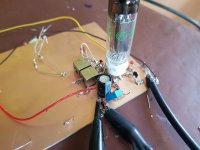
It has a 10'' speaker whose main T/S parameters (Vas, mms, Sd, Re, Qms, Qes, Qts and Fs) were precisely measured more than 6 times after I built it.

I sanity-checked every instrument and my calculations, nothing wrong in there. Every re-test got always very similar results and they're all very consistent with other measurements made before I built the speaker (as the Mms, Cms and Bl).

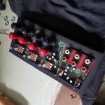
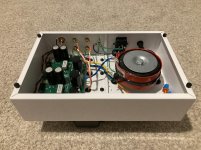
The box couldn't be simpler, it's a 2 cm thickness MDP box lined with felt. Measuring its volume is a rather trivial task, as well as estimating the correction due to the speaker baskets and magnets occupying part of that volume (final estimate was 42 L).

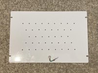
It has a 83 mm circular opening in the front, right at the side of the sub:


j24w39Q.png


That should count (as far as I'm concerned) as a double-flanged 20 mm in length and 83 mm diameter port, but, spoiler alert, the end correction is very far from even being relevant to the discrepancies here.

I've found said discrepancies because I calculated that if I put a 70 mm diameter 55 mm length vent in the opening it would give me the "flatest" response, plus a large gain in the low-end.

Reality was the inverse, the low-end was nearly entirely louder (obviously louder) without the vent, only below 45 Hz it became louder with it, 45 Hz being the point where both configurations where equally loud (and once I'm comparing a frequency with itself, differences in room response and hearing sensitivity don't interfere, they would if I were comparing responses at different frequencies).

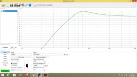
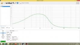
This made no damn sense considering this here was the spl graphs for a same small signal (green=without added vent, red=with added vent):

5nXfY41.png


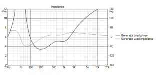
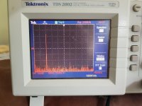
So, as I was sure of the T/S parameters, I've decided to make impedance measurements with the speaker on the enclosure.

Without the added vent I found two maxima, one in 42.8 Hz and other in 86.7 Hz, the second maxima having a higher impedance.

Then, going back to WinISD and changing only the box tuning down I could get the maxima in the impedance graph to match (as well as their magnitudes), but this required tuning the box down to 48 Hz.

Then I made it again with the vent added and it matched the box tuned in 41 Hz in WinISD.

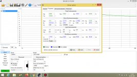
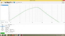
Then, comparing the SPL graphs I got in WinISD, it finally made sense with reality:

uUdbyB5.png


The point where both generated the same SPL was around 50 Hz. Not exactly what I found by ear but close enough, and now everything is coherent with reality and the measurements I made.


But the question remains: How in the hell can this box be tuned so low with these vents?

According to WinISD, both would need to be about 110 mm in length (with their respective diameters) to match that.

What in the world is happening here?

Ps.: I'm also feeling a bit stupid for having all of this work and finding that, apparently, the optimally flat response required no additional work, just the original opening, being that I made an entirely different speaker and no attempt was made to match the original.

TU-8600SVK RCA hiss

I just upgraded to some higher efficiency speakers and started to notice a slight hiss when the volume is turned up all the way. The hiss starts at about the 12 O'clock point and increases until the volume is at maximum.

I've experimented with different electrical outlets, etc. but what I found is -

There is no hiss without the RCA attached.

If I attach the RCA cable to only the amp side, leaving other unattached, there is hiss.

If I attached the cables to the amp and DAC, without the DAC being turned on, there is no hiss.

Once I turn the DAC on the hiss returns.

I'm assuming this has something to do with the soldering and ground in the amp and I will probably take it apart this weekend but is there anything I should pay particular attention too? I really don't have a clear understanding of how the grounding and ground loops come about.

Thanks,

David

Adjusting the volume of a DIY encosure plan

If I have a "proven" back ported enclosure plan, and I want to modify it by adding a box inside that will contain an amplifyer, there will be a reduction in total volume.

Should I adjust the design, for example by increasing the depth of the enclosure, so that the volume remains equal to that of the original design ?

Also, if the original plan has crossovers, and the crossovers are replace by the DSPs in the amp (for ex. a hypex plate amp), given that the removal of the crossovers will recuperate part of the lost volume, should it be accounted in the volume compensation ?

in otherwords, should volume be adjusted with :

NEW_VOLUME = ORIGINAL_VOLUME + AMP_BOX_VOLUME - CROSSOVER_VOLUME

?

Ouput transformers in UK

Hi

Can anyone give me any guidance on where to obtain output trannies in the UK.
Not looking at anything specific just at the moment, but the problem I'm coming across is that UK suppliers seem to be extortionately priced in comparison to Edcor for example. I'd be going for Edcor except they won't ship to the UK or EU.
For example an Edcor 15w 4ohm is priced at 47 usd, anything from the UK is in £100's, a similar Sowter for instance is listed at £243.
I'm not all that knowledgable about OT's so may be missing the point altogether, but if anyone can give me more clarity it would be much appreciated.

Arc Audio ARC2500-CXL

This one keeps cycling on briefly then straight back off. The power led lights briefly. No other LEDs. None of the large transistors are blown afaik. Found one broken rectifier leg so removed all rects. Ps powers on without rects. New rects in, and amp won’t power -only briefly cycle.

Amp is using sg3825. I was thinking about raising pin 16 to see if the amp will power and hold fir further troubleshooting.

I don’t know if a Clarion SM will match here?

Creative E3

Hi,


I have the Creative E3 that was not used for at least 1 year due to COVID.


The battery has bloated, and I changed the battery. However, after changing the battery (the protection board is unchanged), the unit gets very hot and I am not able to power on.


I then removed the battery, and just plug into a USB port. The whole thing just cannot power up.


Can someone advise what have I done wrongly?


Regards.

Transformer saturation

I think I got this but am not sure. I try to read about it but I find everything magnetics very hard written. So let me explain my understanding if I can in a simple way. Then I'd love for one of you who understands this to say yes or no go back to school...
Lest say we have a perfect transformer, the secondary 100% coupled to the primary. The secondary will set up a magnetic field that completely nulls the primary's field so the core is not loaded at all due to load current.
What does load the core is the magnitization current due to the finite value of the inductance in the primary coil. Since the primary's reactance goes down with frequency, if the voltage level is the same as the frequency is lowered, the core will saturate only because the magnitization current becomes too high. The secondary does not create opposite EMF to null the magnitization current.
So the core's max flux density and saturation current is the same whether at DC or at 1MHz...

Edit... I know, the current thru an inductor increases forever if DC is applied over it. So I mean very low frequency, not really DC. But the current level, if one could stop at the saturation level at DC, is the same if very low frequency or very high frequency.

In a real transformer the secondary is not fully coupled to the primary, and does not set up an equal but opposite EMF, so now the core will saturate due to both the magnitization current and the load current. But there is some back EMF from the secondary so still it is the magnitization current that dominates saturation.
?

Thanks for any clarifications...

DCX2496 ASRC question

Been testing my DCX2496 with various SPDIF/TOSLINK inputs, and have had mixed results. Wondering if it is possible to tap into I2S, if it's even available at this stage in the DCX (prior to DSP).

My thought was to use a an external USB/I2S ASRC converter and tap into the output of the existing CS8420. It is not easy to understand the data sheet of the CS8420; I know it has I2S capability but not sure what it's set up for.

Would this address any jitter problems that I current have with SPDIF inputs? I am not familiar enough with I2S to fully understand what I am gaining, but my understanding is it corrects the input signal perfectly, thereafter only being subject to the system clock to which it is feeding.

Choke/tx loaded CF question

I asked some questions about this a while ago, and got useful answers. I learned that my small power pentode CF will pass 25mA when loaded with a choke with a DCR of 160ohms, so all good, Now if I change to a line output transformer with a DCR of 660ohms, I understand that I need to add a negative bias supply to the bottom of the Primary, my question is, What range of negative voltage do I require to overcome the extra 500DCR, and have some adjustment for tuning, more questions to come on this little project but the answer to this one will help right now. Thanks John

Dual channel 10 meg/samples USB oscilloscope

2 volts max input but much higher voltage with x10 and x100 probes.
25uS max speed/ division.
No trig, positive trig and negative trig modes.
Data logger function.
Analogue display as well FFT display.
Simple Fast Fourier transform display for looking at frequency spectrums.
£19.99 plus p+p
p+p is £4.30 to UK, £12 to Europe and £18 to rest of world (at cost price.)
Comes with USB interface and Windows software on CDROM.
scope.jpg

scope2.jpg

Home Theater DSP equivalent to AudioTech Fischer DSP's?

I started my HiFi journey in the land of car audio. It's an interesting world, filled mostly with your average head unit and door speaker upgrade. Very few, if any people take it much further than that.

I've taken my car quite far, with multiple amplifiers and a completely active setup based on an Audiotech Fischer DSP, the HELIX DSP PRO MK2 specifically.

Some of its features:
- Nearly infinitely customizable 32 band 0.25db parametric EQ per channel
- Time alignment down to 0.005ms per channel
- Phase alignment in increments of 5.625 degrees per channel
- Active crossovers per channel, offering Butterworth, Bessel, Linkwitz-Riley,and Chebyshev filters, with slopes between -6 to -42 dB/oct depending on the filter.

You can almost completely compensate for any and all speaker placement imperfections with this DSP.

You can download the demo of their tuning software to see what else it can do.

I have not been able to find a home theater targeted product that comes close to this level of functionality.
The MiniDSP SHD series is the closest I've found, but they appear to not even be in the same ballpark.

Does anyone know of any products that would compare?

2SJ55 testing as Depletion Mode but are actually Enhancement Mode devices

I'm repairing a Tandberg 3006A amp. It uses 2 J55 and 2 K175 MOSFETs for the outputs on each channel. On each channel, one of the J55s tests as Enhancement Mode (it should). The other J55 in each channel tests as Depletion Mode. These are in the same position. I'm using a Peak Atlas DCA Pro for the testing. Does this represent a problem? I hope not because the J55/K175 are no longer made. I think Exicon makes a replacement but can't remember the numbers.

Thank you.

Help needed - Alternative to DCX2496 or not

i need your help and expertise
My DCX2496 is dead or almost, i'm not able to store anymore my settings and everytime i restart it all is gone, factory reset does not help.
So before buying the same one, I'm asking if there is not a better alternative today.
My objective is simple : crossover for bi-amping my speakers (JBL XPL200) powered by Hypex amps, behind is an EMOTIVA XMC2 used for audio & video
- IN/OUT 2x4 or 3x6 with XLR
- no volume control
- Analog inputs used
- budget max: 1000€ (new of second hand)

What i can see so far is:
- a new DCX2496
- DBX VENU360
- MiniDSP 2x4HD but limited to RCA only
-MiniDSP SHD would have been my preference , but it seems to not be well integrated in a HC environment and cannot bypass the volume control, without saying that it's 1500€.

Any idea would be amazing! thanks a lot

Problem with a Clarion APX 401.4 ! NO SOUND

I got it from a friend 2-3 months ago. Tested the tranzistors with my multymeter and they looked fine.

Hooked it up now for a test run and surprise...nothing comes out. Fan stars spining, green light on the LED...yet nothing comes out the speaker.

First request could be...can I get some service manuals pls? `cause I can`t find none.
Second question...can someone guide me along the proces of trying to repair it ???

What should I search / look out for ?! First thing I`ll do in the morning is test out the transistors. And will keep you posted.

Cheers

Can you help me identify this loctal tube?

I've tried shining on it with a flashlight, UV-light and putting it in the freezer, but to no avail.

It seems to be a Mullard tube, and the last (?) digit is 1.

Rather tall loctal, taller than ECH21 and the likes. Makes me think it's a power tube, but I'm no pro.

I've attached a few pics; tell me if you need others and I'll happily upload 🙂

Attachments

  • IMG_3846.jpg
    IMG_3846.jpg
    978.2 KB · Views: 322
  • IMG_3847.jpg
    IMG_3847.jpg
    737.7 KB · Views: 318

Need help with strange problem

Good afternoon everyone, I have a strange problem with my homemade tube amp it consists of a 12ax7 input long tail pair followed by a 6sn7 driver stage into x4 807 push pull output stage. The problem is that when I input a signal the amp it begins to clip in and out at a certain volume. But what is strange is that when when I flip the off switch and there is still charge in the main caps, I can increase the volume on the input and get a much louder output without clipping (sound coming in and out of existence).

I replicated the situation in a way by putting a light bulb in series to the line voltage coming in and it drops it down to roughly half. With the amp basically running at half line voltage I can get a much louder output than I would if it were running at full line voltage before it does the audio cutting in and out thing. Needless to say, I genuinely have no idea what is causing this I know it is not anything in the preamp because I tested it and no cutting in and out. Could this be arcing inside transformer or something with the power supply? I am for the most part new to amp design but I have been into electronics for a while so this may be an issue derived from shear incompetence. Any input is appreciated.

FS Tea Bag VFET2 boards and 282 2SJ28

For Sale

Tea Bag VFET2 one pair
2SK82 4
2SJ28 2
240 TO3 1

No Power Supply - I used a separate box with powercon connectors

Local p/u (Davis CA) the above plus heat sinks as shown in pic $325

Shipped CONUS only - no heat sinks but with L bracket $355

Thanks for looking

Bob

Attachments

  • IMG_9337.jpeg
    IMG_9337.jpeg
    114.2 KB · Views: 262
  • IMG_9340D.jpeg
    IMG_9340D.jpeg
    102.2 KB · Views: 265
  • IMG_9341.jpeg
    IMG_9341.jpeg
    139.3 KB · Views: 263
  • IMG_9345D.jpeg
    IMG_9345D.jpeg
    67.9 KB · Views: 260

Dayton Audio DAEX25VT-4 Vented 25mm Exciter 20W 4 Ohm

Hi all,

Just wanna see if anyone in the Vancouver, BC area interested in group buy on some

Dayton Audio DAEX25VT-4 Vented 25mm Exciter 20W 4 Ohm

Or any other ones their website carries.

Solen Electronique Inc. | DAEX25VT-4


Here's some information on Exciter or DML,

Check out Tech Ingredient on YouTube about their best speaker in the world.

Or

https://www.diyaudio.com/forums/full-range/272576-study-dmls-range-speaker.html

3.5 ohms into 4ohm amp

Hello, I've build a 2-way 4 ohm speaker that goes down to 3.5 ohms at around 200hz (check the picture for the modeled impedance response). I am worried that my 4ohm amp a TDA7498E will have problems with the current peaks since its rated for 4 ohms (this is the ampAIYIMA B03 Bluetooth 5.0 Power Amplifier 160W * 2 TDA7498E Sound Amplifier Stereo Subwoofer Amplifier Altitude Bass With USB Music Player For Home Desktop Speaker Adjustable: Amazon.de: MP3 & Hifi). Should I be worried or is it ok to drive the speaker with this amp?

Attachments

  • νοτβαδ Impedance.png
    νοτβαδ Impedance.png
    21.9 KB · Views: 118

Help repairing a JVC KW-M24BT

Hello everyone. This is my first time in this forum, but I'm registered in some TV repairs forums too. I'm not an electronic technician, but I like to fix my own stuff 😀

I have a JVC KW-M24BT I got from a friend to put in my car but it wasn't working. I opened it and realized it has a damaged IC but couldn't found anything related to its numbers. Couldn't found the repair manual either.

The PCB number is: KW-M24BT MB PCB. 20170726 Ver1.0

The damaged part number is: 734B1 3475A in an 8-pin DIP marked as IC6 on the PCB.

Did some research looking for the part, the PCB or a broken device for parts but without luck.

Any help on this matter? I'm Attaching some pictures too.

Thanks in advance.

Regards

Attachments

  • IMG-20190414-WA0004.jpg
    IMG-20190414-WA0004.jpg
    163.2 KB · Views: 281
  • 20190414_120256.jpg
    20190414_120256.jpg
    1,023.7 KB · Views: 327
  • 20190414_120305.jpg
    20190414_120305.jpg
    907.6 KB · Views: 483
  • 20190414_120337.jpg
    20190414_120337.jpg
    892.1 KB · Views: 339

Occasionnal noise in audio: grounding issue?

[Solved, 4G interferences] Occasionnal noise in audio: grounding issue?

Hello,


I'm trying to cleanup my audio setup. I assume my PC and DAC are clean. But I've an issue that I suspect to be located inside my amplifier, maybe related to ground wirings.


In the amp, a nice build, I added a speaker protection board, powered by a separate small ACmains/DC12V supply. Initially, that was sometime generating noise in the audio, because I routed the 220V line too close to a PCB input channel. I since moved that 220V line away from the amp PCB, but I have still some noise in my audio, similar to such (like occasionnal capacitive coupling/discharge noise, low level but audible noises).


The noises I get aren't permanent (would be easy to fix). They occur shortly, every hours or so, for half a second, and maybe according to the audio tracks I'm listening to (might be related to audio levels, or dynamics, with the additionnal noise triggered or more or less perceptible; fact is that I perceive more such noises with some tracks, tracks that are clean). And most the time, audio is very correct, with no noise at all.


As a next step, I intend to shield the board and converted I added inside.


I will also rewire ground inside the amp, because it came with:
- ground connected to rear aluminium chassis part, from there, to other parts but via painted metal panels....

- audio ground connected to bottom painted metal panel


Can the ground wirings via painted parts be the cause of occasionnal noises I get? I will rewire them with a common point, bolt and nuts, via paint blanked metal parts.


May groundings/shieldings inside a amp chassis cause such noises or shall I search for other sources for those noises I get?


Shaking my amp PCBs with a wood stick causes no noise. So I assume all components and solder joints are Ok there.

DIY "sub"woofer (correct tuning?)

Hi guys,

I am not experienced at all at calculating enclosures for lows woofers, but I have given it a try down below.

I have a defective CLS-15S (both amp and driver), and I am looking to reusing the box for a "new" subwoofer. It is only going to be used for parties and assisting a couple of 15" 3-way speakers, where I would like some more punch. Both inside and outside.

The Monacor SPH-390TC seems to be a good candidate for that box, as far as I have been able to tell. If you have other suggestions, I am all ears!

I have inserted the 390TC parameters in WinISD and have come up with this response:
Screenshot-2021-06-26-113724.png


The CLS-15S is about 100 litres. I will do a more precise calculation later.

What I am unsure of, is how to tell if the woofer's XMAX is being pushed to the limit. And if that graph above seems to be correct and "functionel" for the needs I have. 🙂
I plan on running the Monacor with a second CLSC-12S board amplifier, which is claimed to deliver 350W RMS. I will parallel connect the 2x8ohm DVC 390TC into 4 ohm for the amplifier.

I know you get a lot of threads like this in here, but I hope you've got time to help me out, as well!

Thanks in advance. 🙂

+/- 12 V Power supply simple circuit?

Hello everyone.

Here is a circuit I am considering using to supply +/- 12V to a couple of op-amps - these as part of an active notch filter for my subwoofer. This will be at preamp level before the subwoofer power amp.

This is the circuit I am considering.

My question is the specification of the transformer - should this be say +/- 15V or something so that the regulators see over 12V?

Can I also make any assumptions on the current draw, my transformer supplier made a calc that for 3 filters (one Op-amp / filter) as 2.88 va, not sure how he did this?!?!

Thanks,

6BN6 FM discriminator

As part of another tuner project here's some results from a 6BN6 for the FM discriminator. Its running at 10.7MHz IF. The output is around +/-4V pk for 75KHz deviation. I've used a double coupled tuned circuit to improve distortion. They are 10k toko coils with the turns/cap removed and 32T wound on each bobbin. The cap over the top was just twisted wire, but for an actual design a secondary winding of 4T would be wound on each coil and coupled with a bigger cap there. The coils require accurate adjustment but a THD of .3% is possible.

Attachments

  • 20210628_151557.jpg
    20210628_151557.jpg
    978.6 KB · Views: 171
  • 20210628_151611.jpg
    20210628_151611.jpg
    729.5 KB · Views: 167
  • Screenshot (47).png
    Screenshot (47).png
    102.8 KB · Views: 170

SB Satori and Seas coaxial floorstander

Hello everybody,
I am currently trying to design my first DIY speaker, a 3-way 10/12”- 5.5”- 1”. I bought seas seas c16n001/f for Midrange and tweeter driver. Now, I hesitate between 2 options SB29NRX75-6 or WO24P-8. cabinet will be similar to this project below with woofer volume from 60l to 65l
I would greatly appreciate if you have any advice on other woofer drivers under 250$ to be used, as this is the biggest question mark for me before I pull the trigger.
Does any one of you has any suitable crossover suggestion for this config?
SEAS The Art Of Sound Perfection...
91/2″ SATORI WO24P-8 / Paper - Sbacoustics
10″ SB29NRX75-8 / Norex - Sbacoustics

Attachments

  • 198543396_4788875354459117_8926729337282569265_n.jpg
    198543396_4788875354459117_8926729337282569265_n.jpg
    144.4 KB · Views: 425

weird voltage

i had mod 3 totally same car amplifier for friends. All of them are working normal with those inverter circuit provide +-25v rail voltages. Now my final mod item for myself which generates +-40v. Those capacitors max voltage are 35v. I really fightened coz my main caps are using mundorf 40v those are too expensive for gambling.
Should I replace the inverter coil to decrease voltage?

Attachments

  • Screenshot_20210627-065229_Slides.jpg
    Screenshot_20210627-065229_Slides.jpg
    315.4 KB · Views: 173

12" & Horn 2-way build

Hi all,

I have some RCF HF94 90x40 horns which I'd like to use for a 2-way active speaker build. I'll be building 3 speakers (left, centre, right) for home theater.
Goal is for something which can play loud effortlessly with plenty of dynamic range. The will also be used for music and need to stand up to the occasional party when the volume gets turned up also! 🙂

Anyway, I'm currently seeking any tips or suggestions for a 12" woofer and 1-1.4" inch compression driver that would work in this scenario. Budget caters for higher end components if worthwhile (without going super expensive though).
What do people recommend?

As for compression drivers, the B&C DE250 seems to get good reviews. Would this be suitable and be able to crossover low enough, or should I perhaps aim for something different or a 1.4" driver?

As for woofers, I'm looking at a pro audio driver to meet the output needs.

Finally, is it worth considering using a sealed enclosure for the woofer to better integrate with subs?

Thanks for your help.
Benno

IRS2092 + IRFI4019 - Not starting. Stuck in reset?

Dear diy'ers,

after reading through many many threads, it is time for me to ask a question of my own. I've worked with discrete AB, AB Chipamps and integrated Class-D before and have used them in many project so far. But currently I am running circles with an implementation of the IRS2092 in combination with the IRFI4019.

Upfront: Intended purpose of this amp and source of parts
I am not making a secret out of it, that the PCB I layed out for the amp is meant to be a replacement for a burned out discrete AB Amp used in an old JBL subwoofer. This project is part of my electronics hobby ambitions, so please keep that in mind, that I did not spend a full-blown development cycle with multiple revisions over the PCB or parts of the schematic (may be that is even the fault already).

All parts are sourced from accountable sources, with some exceptions, everything came from mouser. This also applies to the IRS2092 and IRFI4019, so I take any problems with counterfeit-parts out of the equation.

Environmental Conditions:
The Amp will be powered with a 2x32V transformer, which translates to roughly +- 45V supply voltage after rectification. Supply Caps consist of two times 4700µF (one per rail).

Please note: CSD is not connected to anything but a cap, all UVP, OVP and OTP circuits are not connected in this state.

As reference the IRAUDAMP7d and IRAUDAMP7s were used. The Chip in use is in the SOIC16 package and soldered to a DIP to SOIC16 adaptor for easy parts change and testing.

All tests were done currently with the input tied to GND.

The speaker output is protected by a UPC1237 circuit.

Equipment at Hand:
For testing I have several multimeters, transformers and an old RFT EO213 analog scope.

The problem:
It seems that the AMP is not starting or not properly. I was not able to notice any switching output before/after the inductor or on the LO and HO outputs of the IRS2092. Apart of this, the output (aka. VS) is roaming around 1,5V in this state, which causes a speaker DC protection to trip.

Measuring CSD against VSS shows around 3,09V which brings me to the conclusion that I am even below Vth2 (Which is (|Vaa| + |Vss|)*0,3 = 11,2V*0,3 = 3,36V) and far away from Vth1 (Which would be 7,84V).

CSD seems not to jump around between Vth1 and Vth2, which gives me the impression that it is not trying to properly go through a cycle of let's say an OCP event either triggert by the setting of OCSET or CSH.

I've already changed the IRS2092 just to make sure, but without any changes to the current behavior of the amp. All supply voltages seem to be in spec, as far as I can tell. Vaa and Vss are being generated from V+ and V- by a Resistor+Zener combination and are about +-5,6V. VCC is generated via TIP41C+Zener and measures around 15V to COM (V-).

Honestly I am a bit puzzled currently and would appreciate some hints and may be even someone who shows me the obvious mistake I must have made and which I seem to blind to see :/

Measurement, Schematics and Layout:

Measurements of IRS2092


Schematic of the AMP part


Layout with both, top(red) and bottom(blue) layer.


All help is really appreciated, many thanks upfront!
Projects by fanatics, for fanatics
Get answers and advice for everyone wanting to learn the art of audio.
Join the Community
507,706
Members
7,885,121
Messages

Filter

Forum Statistics

Threads
406,077
Messages
7,885,121
Members
507,706
Latest member
thatchacha10