Acoustic engineering help. Please.

I I am usually in the full range section of DIY audio. I live in Florida so it would be great if someone had some knowledge of Florida statutes involving acoustical engineering. I have lived in my home for five years for approximately 3 1/2 years it was quiet noise free living. Then someone decided to update or upgrade the aerators in a nearby water reclamation plant. They replace the old tape blowers with a newer high speed gear driven turbo charged unit and it turns on and off every half hour to 45 minutes 24 hours a day seven days a week. It is driving me absolutely crazy. Along with a few other residents that live here. I appear to have standing waves in certain rooms of my home that generate up to 58 dB A weighted inside my home with the windows closed. I have complained about it for at least a year now and they said there’s nothing I can do about it. I believe that somewhere there Has to be some kind of law that says that you cannot put these type units in a residential area. Because it has been an intermittent problem code enforcement keeps telling me that they come out there when it’s not running but I don’t think they are coming out at all to listen to it. If anyone knows if it is written down anywhere that this is in some sort of a violation of one kind or another please let me know. It is driving me crazy. Thank you.

Harley Davidson - Bluetooth - Boombox

A totally unique portable speaker, or music box or boombox whatever u call it. There is no similar. It was my idea to name it Harley Davidson because, Its looks like a cool motorbike like a harley 😀 .. got me to name it. I used a bluetooth 5.0 receiver. I used 2 mono tpa 3116 amps, Passive tone filter and my own design vu-meter. 6mm MDF layers and 14mm hush contra front and back cover. This boombox is powered by a 16.8v 18amp li-on power supply.
I am also using 22v with step-up converter. Harley Davidson 5" 2 way stage 3 components speakers. They are driven at 2 ohms. At these values, I think it reaches +200w rms total output. Box design bass-reflex. As you can see, it consists of boxes. Its construction is in matrix structure. I don't think it has been used in this type of system before. I'm probably the first to use it. As you can see, it's a completely different device. In the next videos, I will listen to his original voice. That's all for now.

Harley Davidson - Bluetooth - Boombox - Custom - Diy - YouTube

Look forward to Compatible NAND Memory

Hello, folks
I am using the Zynq Ultrascale+ MPSoC on a custom board and have an 8bit NAND Flash memory to boot from. When I try to program the Flash using the Vitis Program Flash Memory tool I am able to measure the CE pin and it does go low and high so I believe the tool is trying to program the NAND flash but in the Vitis Console window it show 8 bad blocks and fails to successfully write data. The part number of my device: MT29F8G08ADBDAH4-IT

How do determine if the memory I have is compatible with the Vitis Program Flash Utility?

Help with china tube amp

I bought this nice china made amp
It sounds nice and has some power, I believe this is the make and mode / info

REISONG Boyuu A9 EL34 single-ended pure class A tube amplifier EL34Bx2 6N9Px2 5Z3PJx1 D version

I’d like to know what tubes a can roll in it, does it self bias or do I have to do that and if so, how. Here’s some more specs


Specifications:
Output Power: 12W * 2 (ultra-linear connection).
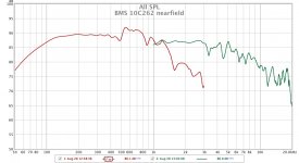
Frequency Response: 20Hz - 28KHz.
Output impedance: 4ohm, 8ohm
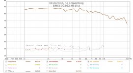
Total Harmonic Distortion: ≤ 1% (1kHz).
Input Sensitivity: 750MV.
Input impedance: 100KΩ (two input signals)
Dimensions (W × D × H): 310 × 220 × 160mm.
SNR: 88dB.
voltage amplification tube: 6N9PJ × 2.
power output tube: Shuguang EL34B × 2.
rectifier tube: 5Z3PJ × 1.
Power Transformers: new imported 0.35, stacked thick 60MM (96-60).
Output transformer core: 0.35 new imported audio-specific piece
Output Block: high-end export-oriented base
Power Supply Voltage: AC 100V - 240V / 50Hz-60Hz (100V, 110V, 120V, 230V, 240V version will take 2-7 work days to order), 220V version is in stock.
Package includes: Amplifierx1PC, Power Cordx1PC

A9 technology
Power transformer: The same imported 0.35 iron core, the same neat and beautiful, the same multiple composite vacuum dipping paint.
Chassis: The same sinking design, the same surface without a screw, the same perfect.
Output transformer: high with plate
Power line: Double high voltage full wave tube rectifier 315V+315V, imported iron core for power inductor, dispatch type power supply filter, imported Phillips/ruby power filter.
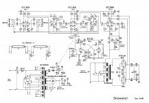
Amplified line: It adopts the Japanese SUN classic line improvement. Each channel adopts two three-stage tube parallel common-acoustic amplification, featuring high output voltage and large driving current. The sound is full and fast, and the high-pitched sound is smooth and smooth.

A9 materials
Power transformer: using 96-60 large power core design power of 200W, high flux thick silicon steel imported 0.35. Oxygen-free copper enameled wire using domestic manufacturers layered tightly wound, with very low load current characteristic, no vibration, no buzz.
Output transformer: divided into segments of tightly wound, using the Japanese ultra-thin electrically insulating paper of pure wood (thickness of only 0.06MM, withstand voltage 2000V).
Capacitance: Imported hifi capacitors do filtering (Netherlands, Philips, Japan ELNA, Japan Ruby, etc.). Coupling using the Netherlands Philips tonic special grade audio capacitors, transparent sound elegant.

D version:
Power transformer 96-60.
Audio dedicated output transformer (76-40)
Shuguang export type EL34B tube A class output.
The new 6N9PJ is amplified in parallel and the force is twice that of the normal line.
Manual welding.

Adjustments.jpg
View attachment 1
View attachment 1
View attachment 1

2S.., 6S.., 12S.. tubes for sale

Sale:
2S4S for $100
6S1J for $2
6S2S for $3
6S3P for $2
6S4S for $25
6S5D for $1
6S5S for $5
6S6B-V for $4
6S8S for $5
6S9D for $2
6S15P for $20
6S17K-V for $1
6S18S for $20
6S19P for $2
6S28B-V for $3
6S29B-V for $4
6S31B for $10
6S33S-V for $20
6S34A-V for $10
6S35A-V for $10
6S41S for $5
6S45P-E for $10
6S46G-V for $3
6S51N-V for $2
6S52N-V for $2
6S53N-V for $2
12S3S for $1.5

Arcam Alpha 10 overheating issues

Hi... I have a Arcam Alpha 10 integrated amp...

The problem is, when I turn it on it just displays on the front panel "Fault overheat" you can clear the fault message but no sound, the speaker relay does not engage so, I bought a multi meter and checked the Transistors, 2 were bad and the thermal pads (non silicon) have NO thermal paste on them, so, was wondering to, replacing the bad Transistors and buy new thermal pads, but use a tiny bit of thermal paste behind the Transistor, all would be ok?

Power tube ratings interpretation?

Hi all,


I've got a dumb question on ratings for power tubes.. sorry if it's been asked / answered a bunch of times already.


For background, most of the power parts I've worked with professionally are solid state (IGBTs and FETs). Their data sheets will have a "safe operating area" plot of VDS vs Id and lines corresponding to time limits - ie, stay under this line for DC, or that one for up to 10us, etc., and your circuit will hold in its smoke. These are "hard" ratings - even real thin pulses poking above them mean that your circuit is probably about to pop.


With tubes, I'll see a maximum plate voltage.. but then the examples in the data sheet run the DC supply right up to that. In a push pull design in a large signal condition, when a tube is headed toward cutoff, its voltage would be headed toward double the "maximum".


So, my question is, are these more like average "DC" ratings, where the plate is actually allowed to approach double that - ie, a 6L6GC would be a 1000V part if it were rated like a transistor?


I see on some data sheets a second plate rating that seems way high - maybe this is the instantaneous one?


Semi related, what do you guys think would be a "safe" B+ to run on modern KT88s and 6L6GCs? I've been reading that the current production KT88s are kinda flimsy compared to the originals, which has got me worried about coming up with a design that's reliable..

Yamaha DA8X modification to AES input

Like to share the recent modification on this DAC. I owned the sets for more than 10 years and besides sold most of the PCM63-KY or Y chips, I never hear the music from this DAC. Here is how I modify it to be useful at home audio. I made it one AES input with 4 channels output L-R-L-R.

Yamaha DA8X convert from Y2 to AES digital input << FET Audio | Hi-End Audio & Electronics

Fostex 207e BIB with tweater???

Wow! Been a long time lurker here. I Built my first ever speaker boxes while lurking this website in 2006 when I was in my 3rd year of college and had my own place for the first time. At the time I built a folded voigt pipe with the 207e. Which it seems is called a BIB. They were 8 feet tall, then over the years I moved and had to cut them down to 7' and eventually had to no room for speakers that large. 🙁 Fostex 207e's have been sitting in a box for 8 years 🙁

I now have a house, some time, and most important motivation. I have been searching this site and have come to the conclusion that a one of the best cabs I can build is a BIB or basically what I built over 15 years ago. As I read and continue to read threads about these great drivers and boxes I am quickly remined and remember the limitations. So I would like to add a tweeter this time around. How does this sound?(pun intended)

I planned on using this BIB calculator

BIB Calculator | Speaker Projects by Zilla

I will try to add a simple tweeter using this method recommend my fostex. Only issue is I don't want to spend $500 on a pair of fostex tweeters. In fact I don't want to spend much on a pair of tweeters. So tweeter recommendations would be great. I was looking around parts express.

http://www.madisound.com/pdf/fostexcabs/fe207e_enclrev2.pdf

I remember missing highs and lows with the old boxes, but everything these drivers/boxes did produce was great. I tried paring my old boxes with different woofers over the years and found it very hard to pair/tune any woofer with them. I hope to try again with a woofer cube (one driver and 2 or 3 passive radiators) Just something I have wanted to experiment with and I have a 10" woofer laying around.


Please let me know if there are any other options or ideas for boxes. This would be a winter project for me I think.


ps. my friend just gave me his FE167e drivers. Not sure what to do with them just yet. Maybe make a center channel speaker? Rear surrounds?


Thank you

-Matt

Attachments

  • sp2.JPG
    sp2.JPG
    163.3 KB · Views: 234
  • DSCN0027.JPG
    DSCN0027.JPG
    188 KB · Views: 232
  • sp4.JPG
    sp4.JPG
    173.5 KB · Views: 234

Selling my vinyl system - Pioneer PLX1000, Nagaoka MP200, Mani pre - like new

$860 prefer to sell locally in PNW. Will consider shipping.

Deciding to sell my vinyl setup. The turntable and cartridge have less than 20 hours. And are in excellent condition.

Pioneer PLX1000 direct drive turntable
Nagaoka MP200 moving magnet cartridge. Installed on Ortofon Headshell.
Cartridge and headshell were professionally setup on PLX1000 by Hawthorne Stereo in Seattle.
The sound is excellent. Just decided to simply my setup and go streaming only.

Let me know if you have questions or wish to see pictures.

my ribbons full range in CB

Hello everyone
For a long time, I've been pursuing the idea of building a full range speaker (I think that's the same for many of you: it's a worthy target without a definite solution). After my first experiences with the AMTs I thought this was the right configuration, so I made many accounts and several AMT achievements. Unfortunately (I say unfortunately because I took a lot of time) I realized that the solutions to have good low at levels around 100 dB are antithesical to the solutions to have good highs, and no acceptable compromise can be found. So I went to the ribbon drivers, or, to be more precise, to almost ribbons.
Not everything that follows is a preliminary study. Much has emerged during the constructions which at the moment are at the end of the first phase, building a shorter ribbon.
Other points I have set are:
1) Put the driver in a closed box of non-prohibitive dimensions, possibly 100 liters, max 200, which already limits the design.
2) Maximum air volume displaced between 200 and 300 cm ^ 3 peak
3) efficiency will naturally be low but I would be happy to put in my room 100 dB with 100W
I started to make a few accounts on the Vas parameter, which in my case seemed to me very important, and combining well know equations I get:

Vas = 10,35*Sd^2/(Fs^2*Mms)

As with other factors, the volume of the box must be proportional to Vas and, according to the equation, to limit the volume of the box Sd must be small and Mms large. However, if I make small Sd, to have the same amount of air moved I need to increase Xp (this is one of the reasons why the AMT solution did not work). By fixing for Xp the acceptable value = 8mm, Sd is determined between 250 and 375 cm ^ 2. To get an idea of the quantum of Mms I put Fs = 25 Hz, Sd = 300 cmq, Vas = 170 liters and get Mms = 30 grams !!! Much above any ribbon. The target set seems unattainable, but I do not win for it, and armed with UniBox software I try some simulation, and I realize right away that I have to quantify the parameter Bl. Then I take the "Magnet" software and start drawing the motor.
One step back: A real ribbon in a closed box is a contradiction, due to side gaps. So I have to close "air-tight" the slots and I thought of doing it with 12g / m ^ 2 airmodel paper strips impregnated with silicone rubber and shaped like a suspension of a cone woofer.
The length of the ribbon I fixed at the first to 92.5 cm, since to make it longer would be a problem for me because the line I have is 100cm long. The width I initially fixed at 4 cm so that the geometric surface is 370 cm ^ 2. For the side suspensions I keep a space of 8mm per side, so in total the magnetic gap should be 56 mm wide.
Then I come back to "magnet" and make a lot of simulations. The target is (of course): the highest possible field and, priority condition, uniform throughout the area as a premise for having low THD. Immediately touch with my hands what you all already know: by increasing the width of the gap over 20 mm, the field strength decreases rapidly and at the same time degrades uniformity. While the intensity is issue of the volume of the magnets employed (I want to keep it to a minimum, being a little shred), for the uniformity after a lot of work I arriving at an acceptable design

Attachments

8" x 1.5 hyperdome

I noticed the 8 inch 2way combo has a bit of a following over at DIY. Is there much buzz around these ones? Energy 22 Loudspeaker System Manual | HiFi Engine

I'm getting a pair midweek. I knew of them, but have never tried those particular Energy's.

If someone can clarify there was 3 models at the time, and the RC were mid tier?

They spec 200 watts power handling. Which seems nice, I wasn't expecting quite a high rating for these little numbers. There not the most efficient. That should be okay I have something that should be powerful enough.

Was it the RC that get the problematic tweeter fluid by the way? Or did all of them require a fluid job in order to function properly?

3 way OB with 15' woofers and 4.5" mids a bad idea?

several years ago I built an OB with two 7" Scanspeak illuminator and a Raal 140-15D dipole ribbon, with a separate 18" dipole sub. The crossover is a 3 way DEQX and the amp a very nice 6 X 125 watt Vecteur AV6. The WAF was low, as they were never properly finished, and after we re did the living room I decided to make something that actually looks nice or at least finished.
So after some research, I purchased 4 AE dipole 15 woofers, intending to add them to the 7" midwoofers and ribbon. I was never fully satisfied with the mid to upper mid range of the 7" illuminators though. The little wiggle at 1khz may be a clue as to why. So then I went down a rabbit hole and decided to get four 4.5" Scanspeak illuminator mids.
With only a three way x-over, the plan at this point is to have the 15s crossed over to the 4.5"s at about 300hz, then to the tweeters at maybe 3500.
My doubt is weather there will be too much of a directivity mismatch between the woofers and mids. I had read that the AE woofers can be crossed over quite high, but I assume that the off axis directivity will not be ideal. Is this just a plain bad idea?
The other option is to keep the 7" midwoofers and add a passive crossover, probably between the mids and tweeter, with the active treating the mids and tweeter as one driver. I have no experience with building complex passive x-overs though and I don't have tons of time to study up on them...
Thanks for any constructive advice!🙂

Setting the bias on an ESP P101

HI guys,

On another thread, setting the bias on my P101 came up. It was suggested that I measure across the souce resistors and set the bias by adjusting to .09V. The P101 that I built is a three channels. I had a problem with one channel when I put it together due to a errant drop of solder causing a bridge across two diodes which took out the VAS transistor. I replaced the transistor and corrected the solder bridge. One of the output MOSFETs read a little different than the others but I only had continuity from source to drain so I went ahead and installed it and the channel seemed to play fine.

Well, I said all of that to say this. When I took readings on the source resistors last night to try and set the bias, I noticed that one of the source resistors had a 0.00V reading. all the others showed a slight Voltage reading and I was able to adjust them to .09V.

Is the 0.00V reading an indication that the associated MOSFET is bad? The channel sounds OK. Is it possible for the channel to sound OK with one bad MOSFET?

Thanks, Terry

B&W woofer soldering tinsel coil connection

Hi to all,


One of the woofers of my B&W DM601 S3 speakers started to work intermittently and only when applying a slight pressure on the membrane.

After a close inspection the junction soldering between the voice coil and the tinsel wire is faulty.
To repair the soldering i need to remove something that looks like a resin which keeps the tinsel/voice coil glued to the spider.
Do you have any idea how to remove this resin ? White spirit !?

Also , are there any special steps to follow when repairing such a fragile connection? temperature soldering range !?
Attached you can find a photo with the faulty connection.


Thank you!

Attachments

  • IMG_20211119_220848.jpg
    IMG_20211119_220848.jpg
    347.1 KB · Views: 218

Offset-Mouth TH....

While working on the BOXPLAN workbook for the TH-SPUD tonight, I was struck with an idea - would there be any value in placing the mouth of a TH not at the end of the expansion, but offset from it, e.g. at S4 instead of S5 (so S4-S5 becomes a stub that's closed at S5)? The offset could possibly be used to null out one of the out of band resonances that THs can be subject to.

Is it possible to model such a beast in Hornresp?

Quad II help needed...

I have two Quad II amplifiers which I got from a lovely man called Phillip Knighton in Wellington many years ago, and which I have not used for a long time. I was going to go and see him and ask if he could check them over, but I discovered with sadness that he is no longer with us, so I went ahead and tried them. One is fine, but the other does not work - one KT66 does not glow and it makes no sound. I have swapped over valves from the working unit and the result is the same. Phillip had replaced some capacitors (not the smoothing caps) but the resistors are original. Is it worth replacing the resistors (I am not worried about losing originality - I just want a working amp) or is there anything I can check with a multimeter to find the problem?

Attachments

  • Quad a.jpg
    Quad a.jpg
    948.3 KB · Views: 394
  • Quad b.jpg
    Quad b.jpg
    998.1 KB · Views: 348
  • Quad c.jpg
    Quad c.jpg
    852.7 KB · Views: 336

Why do Subwoofers have flatter cones?

It's another odd, basic question from me. If there is a correlation between cone area and bass response why do subwoofers have flatter cones?

The issue seems to be particularly relevant to small subwoofers. If you have a flatish 4" sub with a huge Xmax you've probably got 3" of cone (7 square inches). A more conventional 4" bass driver will give you up to 80% more diaphragm area.

I don't get it.

My experience with Karlson enclosures

Here, just for kicks, is a small resume of my adventures with Karlson enclosures. Most of these were lost to Imageshack, so I though I'd re-post.

Not all of it is fullrange and 100% on-topic, but this is the one place where Karlson fans seem to hang out most.

I first built a pair of K5 in 2011 or so. These are scaled-down from the factory K8 design. Hard to see in the below picture, but they used a Pioneer A11 4.5" fullrange.

01.jpg

I then purchased the last pair of FF125K at Solen (most likely in all of Canada) before they were discontinued. These were better-suited than the A11, which is a bit of a boring driver itself.

02.jpg

03.jpg

The last configuration I tried with the K5 was a transformation to an X5, with an internal K-tube. The new midbass driver was a 5.25" Vifa C13, which did reasonably well in there with a venting mod. The slotted waveguide was driven by a tiny inexpensive mylar dome tweeter.

04.jpg

05.jpg

Overall, the K5 was not a success. There never was much bass and the sound was usually congested.

I then decided to go larger and built a pair of Karlsonette. This was the first K12 commercialized by Karlson. I built strictly to factory plans. I had two drivers to mess with in there: the 8" Philips AD9710 and 10" Richard Allan CG10T.

06.jpg

The CG10T did somewhat better in the bass, seeing how it has a lower Qt, but needed HF help, already being somewhat soft on top. The AD9710's near 100dB high-frequency sensitivity was well balanced by the BP6 gain on the other hand. These could play really loud in a small room, but would have done better in a larger space.

I also tried a DIY coaxial driver in there, made up of Foster 12" woofer and 1.5" dome tweeter, parted out from Sears Professional enclosures. The high-Qt and Vas of the woofer made it perform horribly in the K12.

07.jpg

I tried many schemed for HF augmentation on top of the K12. Here's an EV T-35, I know, it should have been rotated 90°. 🙂

08.jpg

I lost all pictures of it, but I also made mini Smith horns that did well on Karlsons.

Here's a whacky contraption: a huge front-horn compression-loading a Fostex FF125K. Its sensitivity was so high that I eventually used both K12 with AD9710 under it to balance the bass. I likely had system sensitivity over 100dB for 2.83V with this scheme. The horns was high-passed in the lower midrange IIRC and I tried my best to match the low-pass with on-hands components. This was a pretty cool monaural system, though short-lived in my room.

09.jpg

2x40w valve amp missing transistor identification (bias)

Hello! I want to build a EL84 PP amp. I found only one circuit suitable to use with my Dem-Technic 3,4k opt.
Unfortunately one transistor in the bias circuit schematic (attached) doesnt have a identication.
Maybe someone here can help out. Regards

Attachments

  • Screenshot_20211129-112345_Gallery.jpg
    Screenshot_20211129-112345_Gallery.jpg
    145 KB · Views: 155
  • Screenshot_20211129-112414_Gallery.jpg
    Screenshot_20211129-112414_Gallery.jpg
    66.7 KB · Views: 154
  • Screenshot_20211129-112359_Gallery.jpg
    Screenshot_20211129-112359_Gallery.jpg
    49.1 KB · Views: 162

FS: TentLabs Negative Bias Supply

FS: TentLabs Negative Bias Supply [SOLD]

SOLD
One unused auto bias module from Tentlabs in antistatic bag.
75 EUR + shipping (org. price 179 EUR)

http://www.tentlabs.com/Products/Tubeamp/page24/page24.html:
The new Tentlabs / Vanderveen circuit offers rock solid bias, independent of tube aging, music signal or mains power voltage changes. The modules biases up to 4 tubes at exactly equal currents, with the setting of only 1 trimmer. All classes of output stages can be biased, A, AB or B, triode, tetrode or penthode, single ended and push-pull.

An externally hosted image should be here but it was not working when we last tested it.

Need help!.

Hello dear community, I just bought a pair of Monacor DTM-104/8 tweeters to replace in my towers. Specs are:

fs = 1,200 Hz
sensibility =92 dB/W/m ( i kinda doubt for the price they are)
8Ohm, 45W rms .
They recommend 2.5khz crossover freq. I doubt its kinda low for the 1.2khz fs.

I would apreciate some tips, help. To build a high pass filter for them, I tought about 2nd order, around 2.7-3khz .
What you recommend?.
( Im familiar with electronics, amps in general, Im not that " schooled " in crossovers, I build a few crossovers before, ( used online calculator ) but just simple 2nd order ( cap + inductor ) no fancy resistors for impedance " smoothing" , sensibility matching , etc.

Towers have two 6.5' each, 12ohm ! in parallel, no crossover, just a tiny cap for the tweeter ( which are dead , of course). I dont intend to make a 2way crossover for them, they sound fine without one. ( testing by ear, they reach 5k as loud as 500-1K , and beyond that they start to sound lower in volume. ) So they play pretty high.

So having two 12ohm woofers in parallel and the tweeter being 8 ohm. Do I need to " worry " about the woofers being 6ohm in parallel or not. ( original tweeter was 6ohm with one series cap in paralell with the woofers.
I want to build a good pair of crossovers for the tweeters.
( towers they say are 91db/w ( didnt measure, they get loud at low volume but i doubt they are so efficent for their price )
My question is the tweeters are rated for 45w, and my towers ( they don't distort, I was really suprised they can handle that power without sounding like crap ( originally bought them as 5ch system, but used just the towers on my pioneer amp for a long time now.I usually play them at max 60w per channel but they can handle with ease 80-100W ( when i really want them loud, which is rare but I dont want to Fry the tweeters.) ( amplifier is Pioneer a702r , 130w per channel 0.007% thd. ) I dont ever clip it.
Here are some pictures.
thank you !, Bruno.

Attachments

  • DSC04337.jpg
    DSC04337.jpg
    497.9 KB · Views: 99
  • DSC04338.jpg
    DSC04338.jpg
    673.1 KB · Views: 96
  • DSC04339.jpg
    DSC04339.jpg
    778.4 KB · Views: 105
  • m1.jpg
    m1.jpg
    52.8 KB · Views: 115

FS: Lighter Note LDR attenuator

Because I have no use for it anymore I'm selling my LDR attenuator based on buildanamp.com Lighter Note.
I have owned a few passive preamps and this one beat them out by a large margin
The preamp uses ldrs like the lightspeed preamp.The volume set at zero, you will still hear some sound,it’s in the design and never bothered me.
As you can see it's very high build quality and parts and has a custom made front panel, transformer is for both 115V or 230v mains.
Asking 195€.

Attachments

  • 2021-03-28 12.11.40.jpg
    2021-03-28 12.11.40.jpg
    775.8 KB · Views: 973
  • 2021-03-28 12.11.50.jpg
    2021-03-28 12.11.50.jpg
    650.8 KB · Views: 947
  • 2021-03-28 12.12.03.jpg
    2021-03-28 12.12.03.jpg
    431.5 KB · Views: 907

CD Player Skipping on First Track

Hi everyone,

I'm having a strange problem with a Marantz cdp where the first track on every cd won't play. Disc loads and displays the TOC. If you forward to track 2 (or any other track) the entire cd plays perfectly. But if you try to play track 1, it either won't read, or goes crazy and jumps immediately to track 2.

This happens with every cd, so I thought the mech was faulty, and replaced it (cdm12.1/vam1201). I've repaired many players over the years so have a good stock of new mechs around, but after replacing it, I had exactly the same problem! So I tried a third mech, and the same thing happened, so it's not the lasers that are causing the problem.

I've looked for 'obvious' problems, such as something jamming the laser/sled so it can't move right to the end of the track, or the ribbon cable being pulled tight, or any of the leads being too short, etc. The laser itself can freely move from one end to the other, and as I said, three different mechs would not have the same problem.

Anyone ever experience anything similar? I'm a bit baffled at the moment. :spin:

Quad 44 bridge rectifier replacement

Good evening! I'm replacing a faulty W02 bridge rectifier in my Quad 44. I currently have some W10 rectifiers on hand, would that work in the 44? The difference between them are the DC blocking, RMS and peak reverse voltage ratings, which are higher for the W10. I attached a schematic below. Thanks for any input!

Attachments

  • Quad 44.jpg
    Quad 44.jpg
    75.4 KB · Views: 148

Noise from Primare SP32

Hi all , I have an annoying noise which has started on my system , kind of a tapping noise through the speakers , I have tracked it down (I think) to the processor (primare SP32) I mainly hear it with the sky box which is connected with hdmi .
I don't seem to have the noise whilst using my HTPC which is connected with analogue inputs , I have tried disconnecting and reconnecting all connectors .
I also hear it with the test tones , here is a you tube video of the noise I recorded earlier

Speaker noise from primare processor - YouTube


I haven't opened the processor yet , just wondering if you guys had any ideas of what to look for ? .
regards..

UGS-muse preamp 2020 GB pcb kit + Muses Chips

I have a set left (unused), if you have interest please contact me
I ask 170€ + 13€ for shipping to EU as tracked parcel. (Colissimo)

1 x UC Board v1.2
1 x Left preamp v1.2
1 x Right preamp v1.2
1 x Left rear v0.0
1 x Right rear v0.0
1 x Logic power v0.0
1 x Trigger Amplis
1 x Trigger Inputs
1 x Subwoofer Board
2 x UGS Modules v3
2 x Buffer Modules
2 x Encoder Board (Pars)
2 x Salas shunt PSU v1.0 (Eric.D)
1 x External Power v1.0 (Eric.D)
2 x Muse MUSES72320 (Profusion)

Attachments

  • Photo PCB.jpg
    Photo PCB.jpg
    1 MB · Views: 402

Modified JBL L100 Crossover HELP

Okay,

I am a beginner in DIY crossovers. I have a pair of early in-line L100s that I am rebuilding the crossover on. After much research I decided I wanted to keep it simple but still have a high and low pass on the mid and high frequency driver.

I decided to create a sort of a hybrid of the L166/4312/L112 crossover for my JBL L100.

These are the components I am planning using and in this order:

Low - 2.2mh jantzen inductor
Mid - 10uf Jantzen sup z cap, .6mh Jantzen inductor, 15w L pad
High - 4uf Jantzen sup z cap, .25mh Jantzen inductor, 15w L pad

I have all my equipment and parts ready to go, only issue is I am having trouble with the crossover layout. The diagram I drew up seemed simple enough but now looking at the way JBL did their crossovers and utilized the L Pad it’s getting confusing.

I’m looking for assistance on how to layout the crossover using these parts on this fairly simple crossover design? Feel free to draw a picture for me lol.

Thanks in advance!

Variable Loudness modification

I'm going to build my own preamplifier. I plan to use a variable loudness function from Nakamichi 410 where the circuit is shown on attachment. The brochure exposed the characteristic curve as shown in attached as well. It said that the circuit reduced frequency of 3kHz to make the contour curve. I'm wondering that If I were to change the point to any frequencies, which parts should be varied and how much values? Are they only capacitors to be considered?

Attachments

  • C1C74404-66D2-4D0B-A84C-563FD1B255C0.jpeg
    C1C74404-66D2-4D0B-A84C-563FD1B255C0.jpeg
    249.2 KB · Views: 517
  • S__15302673.jpg
    S__15302673.jpg
    167.3 KB · Views: 481
  • S__15302674.jpg
    S__15302674.jpg
    19 KB · Views: 467

Tweeter for Lowther

Hi

I'm planning to cut off the whizzercone of my Lowther PM6a and finding a substitute tweeter.

The Lowthers are running in an open baffle with a Morel UW1258 in a sealed box crossed at 400 Hz.

Any recommendations for a tweeter to mate with Lowthers?

I have been thinking of finding a pair of TAD TD-2001, but i don't know how well they would integrate.

Thanks,
Jeppe
Denmark

Shout-out to Dan of AKITIKA / updatemydynaco

I’d like to give a shout-out to Dan of “AKITIKA” and “Upgrademydynaco”. I have built his GT-102 amplifier (which I love) and bought all the upgrade kits for my Dynaco Pat 4 preamp except the tone control defeat. I have also bought some of his upgrades for my Dynaco Stereo 400 amp. I have been extremely satisfied with everything I have purchased from him and built. Putting these kits together has been easy (great instructions), fun and rewarding and everything works extremely well. I doubt I could even buy the components for these kits myself at the price he charges, not to mention the well-designed circuit boards and other hardware. With everything I have put together from him, the only hiccup on his side was one resistor which was supplied 10K instead of 100K. Within a few hours of e-mailing him an envelope with 2 resistors was in the mail to me. After operating my GT-102 for a few weeks, one channel went louder (with some distortion present). I e-mailed Dan and he replied a couple of hours later that I should check out the solder connections in the feed-back loop (letting me know the components in that loop). I re-flowed those connections and the problem went away. It’s not often that you can get that kind of support from the designer of the product, but that is what Dan gives. Keep up the good work Dan!

ECC99/300B Cascode Output Stage?

I was researching "normal" SET output stages to see if I might want my next amp to be in that family. I found my way to an article on TubeCAD (Class-A2 & Evermore Single-Ended Amplifiers) about A2 that had some interesting permutations regarding driving of the cathode of the 300B rather than the grid. One example shows a mosfet follower acting as a current source on the cathode. I completely misunderstood the intent of that circuit and thought what I was seeing was a gain stage beneath the output triode (like a cascode) and started simulating some versions with ECC99. I stumbled on something interesting - a parallel ECC99 gain stage below the 300B. Below is a version that actually looks like it "works" if one suspends their disbelief regarding simulations. It's intriguing so I'm posting it here for discussion purposes.

  • The ECC99s are biased for about 20mA each and dissipate about 2.5W
  • The input swing (at the ECC99 grids) is less than 20Vp-p for full output
  • The ECC99s do draw a couple of mA each on positive swings - which an op amp can provide easily but the AC coupling may be a problem
  • The 300B is running at 80mA and about 30W at idle
  • The negative rail allows the ECC99 to pull the cathode below ground so the 300B draws grid current, in this case through the secondary (for a little feedback) or a direct connection to ground.
  • Because it's a cascode the output Z should be a little higher than a normal triode stage, I think about 3.5 ohms in this case (with a 5k:8 OT).

Its intriguing because it looks like a way to drive a 300B without a 150Vp-p signal and - if one wants - to achieve some modest grid current without followers driving the grid. You still need many triodes and a negative rail so even if it does "work" it might not be categorically better. So what am I missing? Why wouldn't this work?

Brian

Attachments

  • Screen Shot 2017-12-01 at 6.56.56 PM.png
    Screen Shot 2017-12-01 at 6.56.56 PM.png
    168.2 KB · Views: 741

SERFE - a Single Ended Rush Pair Front End

I have a few Sony small SIT 2SK63 and 2SK79, Mu ~30 and 120V Max Vds. Combined with a 2SJ103 GR to form Rush pair we have a non inverting gain stage. 5dB feedback allows for gain of ~20dB. Predicted THD of ~0.23%, negative phase H2 dominant with H2/H3 ~33.9dB.
I call it SERFE K79 to serve a need for spooky presentation. 🙂
Code:
N-Period=1
Fourier components of V(out)
DC component:-0.0112158

Harmonic	Frequency	 Fourier 	Normalized	 Phase  	Normalized
 Number 	  [Hz]   	Component	 Component	[degree]	Phase [deg]
    1   	1.000e+03	4.000e+00	1.000e+00	   -0.06°	    0.00°
    2   	2.000e+03	9.232e-03	2.308e-03	   90.59°	   90.66°
    3   	3.000e+03	1.850e-04	4.624e-05	    0.81°	    0.88°
    4   	4.000e+03	6.786e-06	1.697e-06	 -134.34°	 -134.28°
    5   	5.000e+03	3.998e-06	9.996e-07	 -179.84°	 -179.78°
    6   	6.000e+03	3.215e-06	8.037e-07	 -180.00°	 -179.94°
    7   	7.000e+03	2.755e-06	6.887e-07	 -179.91°	 -179.85°
    8   	8.000e+03	2.411e-06	6.027e-07	 -179.94°	 -179.88°
    9   	9.000e+03	2.144e-06	5.359e-07	 -179.91°	 -179.85°
Total Harmonic Distortion: 0.230840%(0.230840%)
Pic 2 - FFT spectra at 8Vpp output.
Pic 3 - Frequency Response.

The topology also works for other Jfets, Mosfets, Triodes and Pentodes.

Pic 4 - SERFE ECC88
Pic 5 - FFT of SERFE ECC88 with THD ~0.23%, good H2/H3 ~45.3dB
Pic 6 - Mated to M2 output stage to make 25W class A
Pic 7 - Mated to a 50W class AB composite power buffer.
Pic 8 - 14dB (5x) gain headphone amp version with ECC88

Attachments

  • SERFE K79.gif
    SERFE K79.gif
    15.4 KB · Views: 733
  • SERFE K79 FFT.gif
    SERFE K79 FFT.gif
    17.3 KB · Views: 733
  • SERFE K79 FR.gif
    SERFE K79 FR.gif
    19.2 KB · Views: 637
  • SERFE ECC88.gif
    SERFE ECC88.gif
    14 KB · Views: 645
  • SERFE ECC88 FFT.gif
    SERFE ECC88 FFT.gif
    17.7 KB · Views: 641
  • SERA25 K79.gif
    SERA25 K79.gif
    18.5 KB · Views: 462
  • SERAB50 K79.gif
    SERAB50 K79.gif
    26.2 KB · Views: 388
  • SERHA ECC88.gif
    SERHA ECC88.gif
    19.5 KB · Views: 374

Crescendo BC8000 output drive

Hello. I am currently working on a crescendo bass clef 8k amp. I have a strange fault that I have not run into yet and can't seem to find the root cause. The output section was blown. I removed all the dead components and check for any signs of life with a low current supply. I had nothing. So I changed the output driver board and the 4x tc4452 drivers and powered the amplifier on and had my low side drive square wave on both banks of mosfets. I went to test it again today to finish the amp and there was no longer any drive waves but when I touch my finger on the lpf or the phase shift knobs, I get a low side square wave with my scope on 8.0ms. If anyone can shed any insight on this it would be greatly appreciated. Thank you

Question for SE amp to be used with Oris 150 Horns

I have a pair of Oris 150 horns and am looking at building SE amplifiers for them. I have a pair of large dual 15 inch woofer cabinets (and drivers of course) that will be used with a two channel Crown XLS 1002 amplifier that has a built in 24db slope crossover with level controls. The horns will sit on the bass cabinets.

The amp I'm looking to build for the horns is a 46 single ended amplifier but since I don't need to produce any bass below 150Hz or so I was wondering if it would be a good idea to use the coupling capacitor between the driver tube and the 46 to start rolling off the bass around that range. I'm also wondering if it'd be good to even have a cap in front of the driver tube for the same purpose. The idea is to prevent the amp and the drivers in the horn from having to reproduce the low frequencies below the cutoff point.

The crown amp is going to be used balanced from the preamp but it also has a balanced pass through output. I'm looking to use that pass through connection to connect the SE amps via Jensen input transformers (JT-11P4-1) on the inputs of the 46 amps.

So I guess what I'm asking is what capacitor value range should I use? And if I use one before each tube, I'm assuming that would give me a 12db roll off but would I use the same values for both stages? Is doing both a good idea or should I just use the one coupling cap between stages for a 6db roll off?

Any suggestions? Thoughts?

1967 Echolette Showstar refurb

Hi all,

I recently repaired an old echolette showstar S40 guitar tube amplifier (schematic attached) but there are some open questions. The vibrato wasn't working anymore, so I sourced an ORP 62 photo resistor and a 48V bulb somewhere in the US, and along with a new ECC82 the multivibrator circuit works again. I also changed all of the electrolytic caps in the amp. But here is the thing: with the vibrato off I can properly adjust the EL34 bias to whatever i want it to be. However, as soon as I switch the vibrato on, the bias on the power tubes drops by ~almost 10 mA. So I assume that the vibrato circuit is drawing too much power from the bias supply (although it seems to work fine). Does anyone have experience with this amp? is the bias drop maybe normal? Can anyone infer from the schematic what component might be off, or how much current the vibrato should draw? Any help greatly appreciated!!
Cheers, kai

Attachments

  • Echolette-S40-1963-scaled.jpg
    Echolette-S40-1963-scaled.jpg
    385.1 KB · Views: 231

  • Locked
FS: Ian Canada LiFePO4 SuperCap Addons and Maxwell SCs

If anyone is interested, available for sale are some Ian Canada parts.

The LiFePO4 MKIII power supply is staying put, but the add-ons on top which would be great to utilise but not mandatory I can let go.

2A. LifePO4 MKIII pure power supply with 5 output rails (no battery) $199.99

^^^ Keeping This ^^^

These items are for sale that go on top of the MKIII:

27A. UcMateConditioner 5V KIT (for LifePO4 MkIII,II), $58.00 (QTY: 1)

28A. UcHybrid 3.3V KIT (for LifePO4 MkIII,II), $45.00 (QTY: 3)

29A. UcAdapter KIT (for LifePO4 MkIII,II), $29.00 (QTY: 1)

This is a standalone product:

26A. UcConditioner 3.3V (Universal), $67.00

Still in excellent condition as the above items were removed from the sealed pouches, but nothing beyond that...

I can let go of one item above @30% off Github retail price, two items @40% and all of the above @50% off.

The Maxwell BCAP0325 P270 S17 are $13 each on Mouser (Supply Shortage currently). (QTY: 10)

https://www.mouser.com/ProductDetai...BCAP0325-P270-S17?qs=W0yvOO0ixfEdTlheTlBpDQ==

I can let these go @$12 each, I paid close to $15 each originally. But the buyer is responsible for shipping fees.

PayPal only. We can decide how to handle PayPal fees at a later point.

I haven't decided on International Sales yet as I don't know if SuperCaps will be treated like Batteries. Something super difficult to ship.

What glue for grille cloth to wood grille?

What glue can I use to glue the grille cloth to the grille wood?
The current cloth is peeling away from the wood grille - it's 30+ years old.
I tried some gorilla glue, but didn't seem to stick.
Is this glue ok?
Do I need to sand the existing wood grille to make it stick better?
Do I need clamps to keep the grille cloth pressed against the glue to help it bond?


Thanks

BMS 10C262 coaxial build

I have built closed box with BMS 10C262 recently. The box itself is trivial, though a bit oversized for this driver (35l). I would like to post some measurements for those interested in BMS coaxial speakers. Speaker is used for midbass and high frequency duties. It is sitting on top of vented enclosure containing 18Sound 18NLW4100.
Driver: BMS 10C262, 8Ohm
Box: closed, 35l
Crossover: active, Minidsp, 150Hz/1300Hz
Datasheet: http://www.bmsspeakers.com/fileadmin/bms-data/product_data_2019/bms_10c262_datasheet.pdf

The frequency response on official product sheet did not look very nice. I needed a point source and decided to try it anyway. I am happy with the result. It can be crossed nicely and with active DSP it is easy to correct some FR flaws. I replaced Beyma 10G40 + CP-380_M + TD-194 with this BMS build and though I loved Beymas, especially in HF region, I would not go back.

Here is measured raw FR/THD of driver after about 30 hours burn-in period.

Attachments

  • BMS10C262.jpg
    BMS10C262.jpg
    111 KB · Views: 1,315
  • BMS10C262 LO dist.jpg
    BMS10C262 LO dist.jpg
    137.8 KB · Views: 1,136
  • BMS10C262 Hi dist.jpg
    BMS10C262 Hi dist.jpg
    105.7 KB · Views: 1,172
  • bms1.jpg
    bms1.jpg
    383.1 KB · Views: 1,177
  • bms3.jpg
    bms3.jpg
    313.8 KB · Views: 1,106
  • bms4.JPG
    bms4.JPG
    963.6 KB · Views: 872
  • BMSbox.jpg
    BMSbox.jpg
    204.2 KB · Views: 993

Jeff Bagby's Revolution

I was interested to note that Jeff Listed a( either or) tweeter option for the revolution design ( the Be version and the textile dome ) Is this common ?

When I looked at the output of the drivers they were similar - so it made me wonder if- with in -a tweeter Family with similar outputs what should I expect ? are they essentially interchangeable in a crossover design ?

If yes then what are the key measures to look for ?
If not what is the dis-qualifier?

In the case of the revolutions are there others - in the family - that would also work well ?

Help making design choices, large 2-way

After building several proven designs, it's now time to have a go at designing a speaker from scratch.

The basic goals are set (and don't try to convince me otherwise 😉

2 way, 15 inch (mid)bass and a compression driver on a horn/waveguide.
Crossover will be done with DSP.
SPL is not very important, these will be in my living room and will rarely play above 95-100dB

I've been modelling various drivers in boxes of different sizes in WinISD and now I feel stuck. I can model the same freq. response and SPL using very different approaches and I don't really know why I should choose one over the other.

Using a Linkwitz transform, I can do 110dB, f3@35hz with all of these:
Using the Faital 15FH500 in a closed 70L box, in a 120L closed box and in a 100L vented box.

DSP kind of ruins the usual decision making process, and I don't really care if the box will be 70 or 120L. Size is not that important. ~150L is the limit though.

So.... what would be valid reasons for choosing one over another here?
I'm leaning towards a closed box but don't really have a good reason for it. Some say they sound better, but some say vented sound more 'open' or 'natural'.

Are there general characteristics for sealed and ported designs that people agree on?
Is it somehow better if you need less of a boost in the bottom end?

I will have more questions when this is sorted, but first things first 🙂

Thanks

Crown IC-150 with white noise hissing

Hi everyone,

My Crown IC-150 has a fairly loud hiss in the right channel. The white noise level or pitch is not affected by volume, balance, input, or panorama being adjusted. It does change pitch some when I adjust the bass or treble.

If I use the tape outs signal is good, no white noise but tape outs bypass almost the whole pre amp. I have cleaned and looked for problems but noise is still there.

I would love to get this going again, about to buy oscilloscope to try to trace. Other options or thoughts? I would greatly appreciate!

Technics SL-1301: To time tracking adjustment using oscilloscope

Hi All,
I’m adjusting per service manual after replacing caps (some were out of spec) and some diodes ( might as well while I’m in there) and I’m trying to adjust VR101 for T0 between 8 and 8.5msec. The horizontal line is roughly 1 msec on my oscilloscope, and the service manual points to somewhere in the middle of the horizontal portion of the waveform. If you look closely there’s a small bump there, which I don’t see on my oscilloscope. Do I estimate the middle of the horizontal line as the To endpoint? Any help is appreciated.

Attachments

  • 74D0D5CA-CE43-46BB-855A-C8F04ED4787F.jpeg
    74D0D5CA-CE43-46BB-855A-C8F04ED4787F.jpeg
    74.2 KB · Views: 143
  • 3F8BCD2B-153C-4951-B1DC-5AF7560C92DC.jpg
    3F8BCD2B-153C-4951-B1DC-5AF7560C92DC.jpg
    979 KB · Views: 151

ECL86 pentode section help me find a new sleeper tube?

I'm trying to find other noval sized pentodes that come generally close to the characteristics of the pentode section in the ECL86 / 6GW8 tube. I don't know where I'm going with this yet but ECL86 are 50-60 bucks a pop now. Do they have some sort of rare magic fairy dust at that price? No they are just getting rare.

So I was thinking it might be worthwhile to try to find a new "sleeper tube" that comes close to an ECL86 pentode in the most important characteristics. Within a couple watts of plate dissipation, high transconductance, somewhat close on load, etc. The triode in Ecl86 is of no concern here. Here is the list I've compiled so far. Many of you here can remember tubes and data off the top of your heads. Am I barking up an empty tree here, is this futile?

ecl86

https://frank.pocnet.net/sheets/191/6/6GW8.pdf

possibilities...?

6cl6

https://frank.pocnet.net/sheets/127/6/6CL6.pdf

6cw5

https://frank.pocnet.net/sheets/127/6/6CW5.pdf

6ck6

https://frank.pocnet.net/sheets/201/6/6CK6.pdf

6ca5

https://frank.pocnet.net/sheets/093/6/6CA5.pdf

6bj5

https://frank.pocnet.net/sheets/201/6/6BJ5.PDF

6cn6

https://frank.pocnet.net/sheets/201/6/6CN6.PDF

6cu5

https://frank.pocnet.net/sheets/127/6/6CU5.pdf

USB active XO alternatives?

I have been thinking and looking around for the last couple of days, thinking that things would have happened to make me go back to active XO setup 'on the cheap' again, but I can't really find what I'm looking for, so I'm hoping to get a discussion going, and maybe some good info will surface 🙂

Here is the background story:

Some years ago I started experimenting with a setup with Win10 laptop, Foobar, EQ APO, and running HDMI to a surround receiver. This was functional, and very interesting to play around with and listen do different XO points, slopes, time alignments etc, but I guess there was some SQ limitations with the HDMI interface/receiver DAC/ Receiver amp stages.

I replaced the receiver with a AUSUS Xonar 6ch soundcard and three stereo amps (played around with several DIY amps). I was pretty happy with the SQ, but it was messy with cables everywhere, especially having a long USB cable from the laptop in the sofa funning to the sound card by the amps. I also missed having a remote for volume control. I had to use 'digital volume control' in the laptop which is not good for bit depth.. I even bought a relatively cheap 6ch volume control with remote, but the SQ/noise was a lot worse than with digital volume control.

I got tired of the cable mess, stacks of amps etc and bought a SMSL Sanskrit 2ch DAC feeding a single class A amp, and made passive XO's for my current DIY 3-way speakers (pretty complex and expensive to build those too).
I took an old laptop and installed Daphile on it, and remote control it via web-interface (using phone or laptop). The SQ went up a little (with some reservations), and installation has high WAF. The SMSL DAC has a volume control via remote, witch is also a big plus.
I have been testing various amps in this 'classic' 2ch setup, and feel that they do different things well. I like my JLH class A best, but it is a bit limited in bass control.

Now, some time later, I started to look at active XO solutions again. I thought prices would have gone down, and suitable products would be available.

Ideally I would like a USB sound card with volume remote and built in DSP and 4-6 channels output. I could just plug it in to the Daphile laptop, and it would be recognized as any 2-channel sound card. Then configure the DSP for XO and room correction to the 6 outputs, and run class A amp(s) for mid & tweeter, and some other amp for bass. Also thinking about building some new speakers, so it would come handy for that.
I could also use 2ch in and 4ch out, using active XO for bass/mid, and running passive XO between mids and tweeters. Most of the problems/cost with passive XO IMHO is with low XO frequencies.

I have found some cheap DSP boards, but they all seem to have analog in.
I don't much like the idea to use my USB DAC feeding a ADC and DAC on a separate DSP board. Then again comes the issue(?) with volume control, I would like it on the signal going to the amps. It seems it would be much nicer if the DSP had usb in, and analog volume control on the outputs.

So what are your thoughts? I guess I can't be the only person looking for something like this?
I'm on a budget, so I know there will be some compromises, just hoping to get some input on alternatives!

Crown XLC series: voltage conversion via PC board mod or use external transformer?

I have the opportunity to buy a 220V Crown XLC (install series) amp that was intended for the European market. I live in the US where mains are 120V single phase, and this amp wants to run off of 220V single phase. There is no external or internal "mains voltage" switch on these models.

I have read online that for the very similar XLS series it is a matter of changing a jumper and some other components (some are SMD), and I have info on part numbers for that. Unfortunately for the XLC series I do not know part numbers and PCB locations, and the board do look a bit different, so that might be a dead end. Also you need to remove the PS board do SMD work, so it might be a PITA overall.

Since I might actually move to Europe someday, it might make sense to keep the 220V mains input for the amp intact and use a voltage converter while I am in the US. These are a large 2:1 step up/down autoformer type transformer. But I am not sure how well suited (or safe?) it would be to use an autoformer upstream of a class-D power amp that can pull a lot of current at the waveform peaks and is not a steady-state AC draw. Is this unwise?

Also, if/when I move to Europe (Germany) I will likely bring a lot of my 120V US gear over there with me, so I would then need to step down the voltage for any equipment that I could not convert internally. Having a large (several kVA rated) step up/down transformer would useful for that, if it is appropriate to use one with audio gear.

Thanks, any insight would be appreciated.

LM3875 Brian GT chipamp kit or NILES SI-1230 (LM3886) modules bridged or zr-4630 ?

I seem to always have enough power, but I like more power 😀
Are the Niles modules "audiophile" quality? SI-1230 or zr-4630
Or worth it to make a bridged amp out of?

I think I have a transformer for the Niles modules, that's why I ask about them.
35v x 2 -- 750 VA

Are they easy to wire up?

Other option is Brian GT (single) LM3875 stereo chipamp kit. I built one of these years ago. Sounded great.

I seem to always have an issue with too more power coming from an amp. As in, I use the attenuator way at the bottom of it's range and fine adjustments are hard.

The Brian GT amp was like this (not enough attenuation ability) and my current NAD envelope 2100 is also; I can't adjust it low enough a lot of the time.

Basically I want more power of 2 - LM3886 chips bridged, but I DO NOT want to do it if it's not "audiophile" quality or if it's complex to wire up or figure out how to wire it up.

#6 soder wick

kinda hard to find wide size that's good for tube sockets and terminal strips - listed on eBay five rolls five foot length for $13.99 plus first class shipping (I believe this is a favorable price - I don't know how to handle payments here nor how to coordinate a diyaudio listing with an eBay listing so I'm just referencing the eBay listing - I hope that's OK)

Wharfedale - Woofer Phase Plug???

Wharfedale have been making woofers with phase plugs for awhile now. Why?

I had a pair of Wharfedale Reva 4s a few years ago and the dedicated woofers had solid metal phase plugs (Not dust caps). It appears the new acclaimed EVO series speakers use the exact same drivers for the woofers as well. It seams to me to be highly flawed design. Did they just have a stock pile of these that were originally mid-range/woofers and they decided to use them up?

Is there any reason at all to use a phase plug on a dedicated woofer?

It always bothered me on the Revas. You technically get blow-by and/or chuffing from the air moving between the cone and the phase plug. PLUS, the phase plug represents a portion of surface area that could have been used to move more air had it been part of the cone. It is lost energy. No?

TK2050 Extremely successful modifications -- list, pics, review

With an input-cap-mod/24v battery TK2050 board, I was not impressed. Only the midrange was good. I switched back to my Gainclone.

With this fully-modded/24v battery TK2050, I will never use my Gainclone on my main system again. I would put my TK2050 up against the RWA Signature 30.2 ANY DAY OF THE WEEK.

I now own a truly ultra-fi amplifier. I have never heard anything like it. I will not bore you with terms like "liquid highs" -- it is simply the best amplifier I have ever heard.


Mod List:
Power: 2x12v 5ah SLA batteries, wired in series.
Input Stage: DACT-Style 10k stepped pot, 2.2uf 250v Aerovox AFPS input caps, C17 R14 C25 R34 Removed, Limiters (on the bottom of the RCA jacks) removed.
Output Stage: 10uH 68-1 Toroidal coils, .47uf 160v MKP10 differential-caps, .22uf 100v MKP2 common-caps. Low-pass is about 71Khz at 8ohm.

Supporting Mods:

-Tank capacitors changed to 2x 2200uf 35v Nichicon Fine Gold
-Tank bypass film caps changed to WIMA MKP2 .22uf 100v
-TC2000 chip capacitors changed to 100uf 35v Nichicon Fine Gold, 100uf 25v Muse KZ

Note: The output stage is just as important if not more so than the input stage. People generally upgrade their input stage first, as it's cheaper/easier, but the parts on your output filter are just as important!

Also, upgrade signal path parts first, then do power cap mods!

_DSC3422.jpg


_DSC3424.jpg
Projects by fanatics, for fanatics
Get answers and advice for everyone wanting to learn the art of audio.
Join the Community
507,765
Members
7,887,482
Messages

Filter

Forum Statistics

Threads
406,178
Messages
7,887,482
Members
507,765
Latest member
aleminx