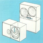
This is the new thread for the 2x 21" down-firing-port subwoofer build(2x B&C 21SW152-4), it was previously discussed
HERE in regards port design suggestion.
This 21" subs will replace the current single Ultimax UM18-22 in a 5-FT^3 sealed enclosure, wanted some lows, strong midbass and low distortion on my 2CH music setup.
Final project specs:
Material: 6x 5/8" MDF-Light 4'x8' sheets.
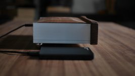
Measures: 42" H x 24" W x 27" D, (46" H with feet), nominal.
Walls: ~1.25"(dual 5/8") thick walls, ~1.9"(triple 5/8") baffle with braces.
Finish: Black-mate laminate.
Volume: ~9.5 FT^3 Net. after port/driver/bracing.
Weight: ~222 lbs (~180 lbs without driver)
Initial subwoofer testing/setup:
DSP: DBX DriveRack PA2
High-pass xover: 16Hz BW4
Low-pass xover: 60Hz LR4
PEQ's: Off
Delay: Off
Subharmonic Synth: Off
My "subjective" listening impressions:
After getting them in place and connected, I've played some EDM and Pop music and I was a bit skeptical at first, then I remembered that I had to invert the subs phase, after inverting the phase resulted in an instant jaw-drop followed by an ear-to-ear smile, one box just blown away the sealed UM18-22 and I've disable the PEQ's previously boosting the 20~28Hz range on the sealed sub.
Notes worth mentioning:
The B&C 21SW152-4 drivers were installed without any breaking-time, so the subs will significantly dig lower overtime as expected.
The room measurements are 10'-9"W x 9'-2"D x 8'-4"H, just small.
The enclosures were tuned to ~19Hz regarding WinISD, however since the 8" port clearance from top wall is 7.75", port clearance from floor is 4" plus 2 large pillows, the final tuning dropped to around~17 or 18Hz, while I don't had at hand DATSv3 nor a diy impedance jig, I've tested with an adhesive tape and cranked up the amplifier and used a tone generator, so far when the tone generator was set to 17Hz, the woofer drop excursion dramatically and everything in the room was insanely shaking and I feel the high pressure, I didn't hear any port noise/compression when testing so far.
Complete step by step build log HERE
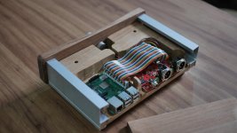
Some build images:
The triple front baffles.
Deluxe 6 prong T-Nuts epoxied.
The
Ankh shaped braces and port support.
Gluing started next to a 16oz glue bottle for size reference, I've used my favorite glue TB3.
The braces in place.
Interior view of the port supporters embedded on the braces.
Spreading a generous amount of glue per brace and top/bottom walls.
Internal preview of one box almost ready, back wall non yet glued.
Port dry-run test before sealing it with RTV and gluing the back wall.
Port top/brace clearance.
Port being sealed with 100% RTV.
Applying few turns of Scotch blue tape for port tighten.
Port being evenly pushed gently with a small piece of wood scrap and a rubber hammer.
Port back view.
Complete step by step build log HERE
For reference the mains build log HERE
Regards

 ) , this one differing on outputs being classic BJT complementary pair, so sorta blasphemy in Papaland ......... he sinned heavily eons ago ....... while my Sin is recent........


