Light as Air Slot Loaded Band Pass Sub

Is anyone tired of lugging around heavy subs made of plywood or mdf? It doesn't have to be that way if you don't need manly man boxes that can double as car jacks or stepping stools to reach a ceiling light. If portability and ease of transport are important - or you don't want to make sawdust or don't have powertools like a table saw or router - items that are de rigueur for speaker building, this may be the thread for you.

There have been several threads (http://www.diyaudio.com/forums/subwoofers/258275-ppsl-2-sigma-pro-18-2as.html and http://www.diyaudio.com/forums/subwoofers/177905-thread-those-interested-ppsl-enclosures.html and http://www.diyaudio.com/forums/subwoofers/242321-dual-opposed-slot-loaded-port.html and http://www.diyaudio.com/forums/subwoofers/255959-sim-slbp_pp-maybe-more.html) about slot loaded push-pull bandpass subs lately, but almost all with big 15 in or 18 in drivers and requisite heavy plywood boxes that go with them. I have been building lightweight foam core speakers over in the full range forum for some time now and thought I should give a dedicated real subwoofer a go at it with foam construction. Rather than the 3/16in thick paper faced foam core from the dollar store, I will use 1 in thick XPS foam insulation sheathing (pink stuff from HD).

I decided to make a compact sub with two 16-ohm 5 inch class Tang Band subwoofer drivers that I have on hand (W5-876SE). I modeled the design in Akabak and aimed for a moderate 45 Hz tuning frequency in order to keep a good efficiency (planned for a corner loaded placement). The design ended up at about 8 liters per chamber with a 0.5 in deep x 8 in tall x 14.5 in long vent. The central slot was set at 4 in wide x 8 in tall x 8.5 in long. The overall box including thickness of wall panels ended up at 10 in x 11.5 in x 24 in. What I built probably resembles this the most:

An externally hosted image should be here but it was not working when we last tested it.


The construction was accomplished using hot melt glue and the final panel was glued with liquid nails. The weight of the enclosure without drivers is very light - I would say on the order of under a pound - feels like air.

Installing the drivers was tricky because I should have made the slot about 4.25 in wide to accommodate the depth of the driver and magnet during installation. As it is, the surround of the second driver had to rub against the first one in order to get it in. I ended up setting them both face out for easy access to the screws.

The simulation predicted about 95 dB at 2.83 volts at 1 meter at 45 Hz before falling off:

426173d1404104201-light-air-slot-loaded-band-pass-sub-slbpsub5-1watt.png


Predicted xmax of 5 mm is reached at 21 volts if using a 39 Hz -24dB/oct high pass filter. Max SPL is about 113 dB - not bad for a couple of 5 in drivers in a foam box:

426174d1404104201-light-air-slot-loaded-band-pass-sub-slbpsub5.png


The construction went together very quickly in less than 2 hours and using no more than a razor, straight edge, hot glue, and liquid nails. Here are the construction photos:

426175d1404104201-light-air-slot-loaded-band-pass-sub-slbpsub5-photo-construction.png


426176d1404104201-light-air-slot-loaded-band-pass-sub-slbpsub5-photo-completed.jpg


I can't make a measurement in an open field so my basement room is full of room modes and other artifacts that cause pretty big dips. However, I can see that the peak SPL at 2.83 volts and 70 Hz is about 95 or 96 dB. Making a measurement at the exit plane of the vent also seems to mitigate some of the room effects:

426177d1404104201-light-air-slot-loaded-band-pass-sub-slbpsub5-1watt-1m-measure.png


How does it sound? Very nice - gets very loud fast. 🙂

Tb46 made a nice drawing of an implementation using the MCM 55-2421 driver for a 30 Hz capable 120 dB sub: http://www.diyaudio.com/forums/attachments/subwoofers/429073d1405690957-light-air-slot-loaded-band-pass-sub-xrk971_55-2421_ppsl_short.pdf

Response with corner placement:
428767d1405511775-light-air-slot-loaded-band-pass-sub-ppslsub1-mcm55-2924-spl-xmax-46volts.png

Attachments

  • SLBPSUB5-1watt.png
    SLBPSUB5-1watt.png
    32.8 KB · Views: 8,869
  • SLBPSUB5.png
    SLBPSUB5.png
    14.3 KB · Views: 8,812
  • SLBPSUB5-photo-construction.png
    SLBPSUB5-photo-construction.png
    544.3 KB · Views: 15,520
  • SLBPSUB5-photo-completed.jpg
    SLBPSUB5-photo-completed.jpg
    163.7 KB · Views: 9,184
  • SLBPSUB5-1watt-1m-measure.png
    SLBPSUB5-1watt-1m-measure.png
    109.5 KB · Views: 9,972

Bias servo with EL84 Baby Huey?

I've been trying to incorporate an AB-Q for 4 tubes, PP & PPP & SE amps into my EL84 Baby Huey. Why? Because it's fun trying this stuff.

My 2 EL84 BH amp boards work perfectly with bias pots. With the bias servo wired-up as shown I've had no success.

With a single BH module and both EL84s installed, one EL84 goes straight through 30mA and on up to 100mA at which point I turn off. The other EL84 starts conducting and then turns off.

With a single EL84 installed, anode current plateaus at 125mA before I quickly turn it off. I can see the AB-Q trying to turn the bias back down on the gate of the MOSFET, but the source of the STU9HN65M2 doesn't follow it.

I'm starting to wonder whether either the use of MOSFET drivers or the CCS with the MOSFET drivers might not be compatible with the bias servo.

Can anyone give me any advice on this please?

Attachments

  • BH EL84 Amp.pdf
    BH EL84 Amp.pdf
    56.9 KB · Views: 191
  • IMG_2929.JPEG
    IMG_2929.JPEG
    531.5 KB · Views: 261
  • IMG_2933.JPEG
    IMG_2933.JPEG
    299.5 KB · Views: 262
  • AB-Q Wiring.png
    AB-Q Wiring.png
    92.5 KB · Views: 310

E drum amp kit or design like roland pm-100

Hey team, New to speakers and amps!

Can anyone recommend a project either a kit or even some ideas to build my own from scratch.

Looking for a amp/speaker combo like the roland pm100
https://www.roland.com/global/products/pm-100/

I've done some googling but haven't found anything but it possible i just don't know what I'm looking for 🙂

Any advice would be much appreciated

is "isolation" a specification in capacitors?

I might need to hire someone to replace some SMD capacitors for me. I sent him a website that listed the capacitor values that need replacing. The website only lists the capacitance though, with no further details. He replied

"There's still one value not given and that's the isolation. These caps have different voltages of operation, so make sure they have the right voltage. Should be over 16V or 50V"

Is "isolation" just another word for the voltage (or an auto-correct error), or is it a specification that I need to work out? The little SMD caps have written things like:
"8F 10 36v"

Which I take to mean 10uf 36v, with "8F" possibly indicating the brand/series/size? I was just going to buy a mix of random panasonic/nichicon caps that suit the capacitance and voltage, without worrying about the exact series

Pulled a newb move and my output wires crossed on DX1000.1 ...

So while testing some subs I rebuilt the output wires for my Kicker DX1000.1 crossed for a few seconds after accidentally pulling on the cable after disconnecting from 1 sub to hook up another, 1st time I have ever done that, man what a newb move ...

I pulled all power ASAP but the damage is done, on my test bench the amp only pulls 3v and is maxing out the 2amp I have it limited too @ idle and puts it in CC mode so I’m sure it’s pull more of allowed, while trying to troubleshoot all the mosfets tested good diode wise, so with my limited experience and wanting to narrow it down to where the damage is I pulled all mosfets.

Amp powers on proper and comes out of protect with no PS mosfets installed, and the middle socket on PS mosfets bank gets 12v, which is telling me the PS mosfets are blown/out of spec sending amp into protect when they are installed on board. I’m guessing driver IC is still good as it comes out of protect and send the proper 12v to the PS mosfets.

I’ve included a pic of the IRFB3077 PS mosfets connected to my cheap o meter, something must be just wrong enough with them to send amp in protect but they still test good diode mode wise and they look functional on meter but I’ve never seen a Cg reading that high on a mosfet before, are these out of spec and can you even tell with what little info this meter gives?

If they are not out of spec but throw amp into protect when installed what else could it be? Any and all info/advice would be great ...still can’t believe I got clumsy and caused those wires to cross, literally has never happened before ...feel like such a dumbass lol.

Attachments

  • D5242C59-8C29-4113-8AF5-87A1EBAC71DD.jpeg
    D5242C59-8C29-4113-8AF5-87A1EBAC71DD.jpeg
    357 KB · Views: 110

Flooded SAE 2400L - Parts Needed

Hello! Since 1981 I have owned a SAE 2400L Amplifier. Unfortunately, the amp was completely submerged in a flooded basement recently. The that shop that inspected the unit tells me that several of the internal components should be replaced from a donor unit(s).

Does anyone out there know of a parts source, or a donor 2400L that could help bring my unit back to life? One of the first components needed is the primary power transformer. Mine is one of the older "square" ones (not an newer toroidal).

Any help or insights would be appreciated. Thanks in advance.

K-12G Tube Amp Kit Build

A fellow on this site was offering a little 4 tube amplifier kit for a very reasonable price. I love building kits and decided to buy it. It is offered by S-5 Electronics and is the K-12G , 8w/ch amplifier. Fun kit to build. Took about an hour and a half. No issues except I had a polarized cap in backwards.....Two of the three face one way and the third is opposite....It got me!.....Flipped it around and all is good! Here is a quick start up video: https://public.fotki.com/Rbertalotto/hifi-stereo-stuff/4-tube-power-amp/p1050125.html

Attachments

  • P1050130 (2).JPG
    P1050130 (2).JPG
    212.9 KB · Views: 167
  • P1050126.JPG
    P1050126.JPG
    522.9 KB · Views: 168

Stabistor Sub for old SS Fisher?

I'm working on a Fisher 450-T (same amp board as 500-TX) and could use help figuring out replacements for the following stabistors: CR801, CR802, CR803, and CR804. When I got the unit, CR801 and CR802 had been replaced with a single 1N4007 each, and CR803 and CR804 with what appeared to be a single signal diode each--these were both open. Based on the schematic and board view notes, it seems like all four of these stabistors could each be subbed with a string of 6(!) 1N4148's for the "-3" version of the board or a string of 4 for the "-1" and "-2" versions (still need to confirm which version I have). The only other thing I have to go on is the part number, which turns up zero info other than its use in many other Fisher components. FWIW, with two 1N4148's in series at CR803 and CR804, the bias can't be adjusted any lower than 50mV, when the spec is 15mV.

Attachments

  • Amp Board Schematic.jpg
    Amp Board Schematic.jpg
    139.1 KB · Views: 297
  • Amp Board Schematic 2.jpg
    Amp Board Schematic 2.jpg
    200.1 KB · Views: 321

The SSSS - single speaker stereo with subwoofer

Inspired by the great results of my 3FE22 SSS implementation, I decided to build a tower version with built in amplification and a mono bass unit. The amplification will be most probably the Zoudio 4ch amp. I plan to keep the width and extend the height so that the FR speakers are at seated ear level. I need to calculate the available front baffle space and volume. The bass unit will play below 200 Hz (+-) and could be actually a bandpass design, so that the speaker is hidden inside.

Some reference links:
https://www.diyaudio.com/community/...-full-range-driver.379277/page-3#post-6884821
https://www.diyaudio.com/community/threads/stereophonic-sound-from-a-single-loudspeaker.200040/

Start Help with the Composite function and its dimensioning, a strange behavior

Hi, everyone,
I tried to understand and recreate the composite function.
Unfortunately, I always have strange effects.
Here is a small excerpt.
I currently have a China LM3886 on the table and a NE5532 on a breadboard

I've tried several things and weird things happen every time.

I think I have a fundamental problem that I can't find.

Here is a rough overview:

In the front where it says ok I have a nice sine wave 1kHz with 500mV p.p. , so ok !

If I take out the composite parts, everything goes fine!
I don't have a DC in the signal path.

As soon as I add the composite components, there is suddenly a DC of 500mV at the + input of the LM3886, on which the sine runs with 1k..

Can anybody help me , please .

SO if i Understand it right the composite should be a overall Feedback from Out Speakter to - of the OPV.
But why there comes a DC of 500mV in the system....?

Attachments

Quad, Ohm, MA, Local (Morgan Hill, CA)

Hi All,

This gear belonged to a local audio friend who passed last year. All gear (except the last Soundcraftsmen tube integrated) are located in Morgan Hill, CA. The Soundcraftsmen is in Mountain View.

Please don't ask for anything here to be shipped, but if you want to coordinate your own shipping (uShip or having a local friend pick it up and ship it to you), that's perfectly fine.

I tested these pieces to get an indication of level of functionality and notes follow each listing. I do have pics of everything, in some cases plenty of pics, but I know local sales have a limited audience and rather than post a ton of pics here, please PM me for pics of any gear you're interested in and I'll be more than happy to send you pics.

1) Quad 405 Amp: $225
Tested and working

2) B&O Beogram RX-2: $150
I tested this and it seems to work fine as far as starting to play, having the cue lever move up and down in response to the button, the speed changing in response to the speed buttons, and auto return.

I'm unsure about the condition of the stylus though. I got music playing a record, but wasn't able to inspect the stylus any further, clean it, etc.

3) NAD 3150 Integrated Amp: $125
Tested working using AUX input and I tested the above B&O TT using the phono input. The first time I fired it up (I don't believe it was used in years), it took about 30s to click into operating mode. The subsequent times I powered it on, it came out of protection after just a few seconds. The controls would benefit from being cleaned with DeOxit/control cleaner, but it seems to be working otherwise.

I noticed the top part of the pre-out/main-in jacks was loose, but the metal jacks are in and this looseness didn't affect the sound. If the plan were to frequently remove the metal U jacks and plug an external amp from the pre-out jacks or use an external preamp into the amp in jacks, reinforcing these jacks is something I would look into.

4) Nakamichi DR-3 Cassette Deck: $250
Tested with a Type II cassette and plays back well. Didn't try to record. Comes with paperwork.

6) Ohm Walsh 4 speakers: $850
The drivers were sent to Ohm in Brooklyn by the previous owner for their standard restoration work. The cabinets are in 9/10 condition, which is kind of rare. The hats can use a cleaning and you might want to recloth, but I didn't see any rips/tears on the current mesh. On casters for easy movement. These were bought by my friend from an audiophile in S.F., who used these exclusively with MC60 tube amps. My friend briefly used these with MC2120's before going with a MC225. So they've been Mcintosh run all their life.

Things to note: There's a ding in the cage of one of the driver as shown in pic. The 8 screw/fasteners to attach the drivers onto the cabs are missing - we'll look for them, but worst case you'll need to find substitutes or contact Ohm to get replacements ($40 for a set, or just use 1/4" 20 thread nuts for less). Also, only one driver cage has the felt on one side. I don't know whether the felt was purposely left off based on the listening room of the previous owner, but there's no sign of stickiness to indicate it was there and fell off.

Sequential serial #'s. These were my friend's main speakers, so they were in regular use, and he loved their sound.

7) Monitor Audio Gold 20's: $550
These were the regular speakers prior to my friend getting the Ohms. These are Made in England vintage, bi-wireable (with wire jumpers in place now). Cabinets in 8.5/10 condition with a few minor dings. They're black speakers, so these can be touched up pretty easily. Grills intact, but can probably use a light cleaning (no tears/rips). These also come with the platforms to give them a wider base, but I didn't see the spikes that screw into them, so you'd need to source some spikes if you wanted to use them with spikes.

8) Martin Logan Dynamo 300 sub: $60
Very good condition. I didn't get around to testing this - I'm sure it works, but you'll want to test

9) Yamaha M4 Power Amp: $200
120W/ch into 8 ohms, A/B speaker selection. 1979-82 vintage.

I used this as my test amp testing a variety of preamps and it worked well during my testing. Power, A, and B lighted buttons all working. Cosmetically, the face is nice, but the cage on top has a few dings and paint chips.

10) Harmon Kardon A300 Tube Integrated Amp: $350

6V6/7408 based integrated amp with MM phono stage. 12W/channel of tube power. Speaker taps for 8 or 16ohm speakers.

Checked this out via AUX input and sounded nice, no issues, all front controls working well. Did not have a TT available to test the phono input. Uses 4 x 12AX7 and 1 x 12AU7 in the phono and line stage in addition to the 4 power tubes. Faceplate is nice, no top cover. Condition is very good - see pics.

11) Harmon Kardon Citation Eleven solid state preamp $175

Tested and everything working

12) Yaqin MC-100B Tube Amp: $265
This has a serious dent as seen in the pics. It also causes the bottom cover to not be flush in certain spots. But despite that, I was able to test it today and verified it working with both front RCA input and the 4 rear AUX inputs. Comes with 4 Electro Harmonix KT-88 tubes installed and 4 vintage 6SN7 tubes. I believe the two front miniature tubes are also vintage, but I forgot to take note of brand.

We'll also include 4 extra Electron Tube KT-88 tubes (untested) and 4 Russian 6SN7 equivalents that test weak.

13) Cambridge Audio 640P and DACMagic Upsampling DACs
a) 640p: $50
Supports MM and MC, missing wall wart. Manual included. Very good condition.
b) DACMagic #1: $125, #2: $100
Supports coax, optical, and USB inputs, up to 96 sampling rate. Balanced and RCA analog outputs.
#1 comes with power supply and manual, #2 comes with disassembled power supply that may not work and no manual

14) Yamaha ATS 1060 Sound Bar: $75
I believe this was used only briefly by a friend of his, then gifted to my friend. It's like new in original box.

15) Sony CDP 302/302ES (2 units available): $50 each
These are old 80's vintage CD players. A friend of ours bought these, recapped them, and upgraded opamps to the 2604 op amp and said there was a big upgrade in sound. These might be for someone who likes the early DAC sound (warm, smooth).

Both units are in very good condition, but have a few marks here and there due to age.

However, I believe both units have an issue with flaky drawers. So you hit the open/close button and the drawer often doesn't respond and needs help. Could be belts, could be lube. Not uncommon in these old units, but needs to be disclosed as an issue that needs attention.

Remotes available for both units.

16) Soundcraftsmen Tri-channel 2020 6BQ5 Integrated Amp: $350

Uses 3 x 12AX7 tubes, 2 x 6BQ5 tubes, and 1 6CA4 rectifier tube. All tubes are included with amplifier. Guessing it's probably about 12W/channel.

This originally had a hum, so I recapped it with new electrolytics and poly film coupling caps.

This was originally missing 2 of its original knobs and I had 4 other smaller knobs I wasn't using, so I put those on the top set of controls and put 4 of the 6 original knobs on the bottom four controls so all controls would have knobs. I'm including the 4 smaller knobs already installed on the unit, as well as the other 2 original knobs.

NAD 314 Power Amp Repair

Hi
I'm in the process of repairing an NAD 314. The Problem is, that the amplitude of the right channel is much lower than on the left channel. The signal of the right channel also has a slight phase shift compared to the left channel. I already checked that the output of the preamp is fine on both channels. They are equal.
The yellow curve is the faulty right channel, blue is the left one.
What could cause this? What should I check?
NewFile1.png

Unbenannt.JPG

Korg Nutube Pete Millet

For sale Korg Nutube buffer build on Pete Millet kit and ready to use with mundorf supreme input cap and Arcotronix output cap, with 24V 5A smps psu. Price would be 150euro plus shipping inside EU or best offer.

Attachments

  • IMG_20220205_095229.jpg
    IMG_20220205_095229.jpg
    605.2 KB · Views: 244
  • IMG_20220205_095142.jpg
    IMG_20220205_095142.jpg
    481.1 KB · Views: 275
  • IMG_20220205_095147.jpg
    IMG_20220205_095147.jpg
    576.2 KB · Views: 275
  • IMG_20220205_095156.jpg
    IMG_20220205_095156.jpg
    686.3 KB · Views: 269

EEEngine

I think this one is the patent of EEEngine. Patent #5,347,230.
It's interesting, because classD principal is used for efficiency of rails, while the main amp still can be classAB or even classA.
The important component is in L1. The right side of L1 (150uH) is classD/square full voltage, and at the left side of L1 it is a voltage follower, following Qb to feed the output transistors Qa. Output transistors Qa is cascoded by Qb emitor voltage at low voltage, so the dissipation in Qa is small (compared to rail that is +/-90V)
If Qb's emitors are sitting at +5V, the from +5V to +90 (85V) is given by L1 from classD mechanism, efficient.

But is this schematic selfoscilating at constant frequency like UCD or not? Is this good or not?

Attachments

  • 5347230.jpg
    5347230.jpg
    46.5 KB · Views: 2,712

Stacking a toroidal PT over a toroidal choke

Working on laying out a little tube amplifier and decided on trying to use one of the Antek toroidal chokes. From a packaging standpoint, I'd love to put the PT (in a case) on top of the chassis with the choke mounted directly below it. I'd probably never consider mixing signal and PSU based toroids on top of one another, but curious what you all think about a choke? I'm not coming up with any significant concerns but would love to hear from the experts on this page. Thanks in advance!

Compact sealed RS225-4 with RST28a and 3D printed waveguide

Hi all, I'm writing a post to share my ongoing project. I've printed one of @augerpro's waveguides and although my print is rough, the sound is good. The project is a box with about 0.35 cubic feet net. My goal is to create something that can serve as a compact wall-mounted speaker for use in home theater, so I want this to be capable of significant clean output. I want it to be a shallow depth wall mount that's able to be mounted in-wall for minimal front wall boundary issues. The prototype is 12" wide, 16.5" tall, and 6" deep with 3/4" plywood construction with a single brace spanning from to back at the position between the waveguide and woofer. Denim insulation lines most of the interior, Here's a picture as it stands now:

proto 8 RS225 with RST28a.jpg


I have the crossover set to 1500hz LR4, there's a Linkwitz transform on the woofer, a 40hz second order highpass, five bands of global parametric EQ, three parameteric EQ filters on both the tweeter and the woofer. I will need to take better measurements before I try to translate this to a passive crossover, but I think it sounds decent right now.

After developing a crossover in MiniDSP I wanted to check how well it could produce higher sound pressure levels. I set the prototype in home theater center channel position and ran sweeps with the microphone in the MLP, a little less than three meters away. The amplifier I used was a home build Hypex UCD180, with one channel for the woofer and one for the tweeter.

proto 8 MLP measurement.JPG


Stacking these traces on top of each other, this is what I see for variation:
proto 8 compression.JPG

I'd love to know the proper way to calculate and display compression, so if there's a convention on how to do that in REW, I'm all ears.

Anyway, as a point of comparison I repeated this with a DIYSG HT8 to similar SPL and generated this:
HT8 compression.JPG

I am presently using the HT8 as a center channel and I don't really notice distortion or compression during movies from this speaker. I do however notice some distress from the JBL LSR308, which are my left and right channels right now, and I moved one to the center position and generated this:
JBL LSR 308 Compression.JPG


So it does seem that the sealed prototype is doing well in comparison. Here are two views of the distortion on the loudest trace of the sealed prototype:

proto 8 max distortion.JPG

proto 8 max distortion 2.JPG

Again, this was over 90db at over two meters, so I think this is a decent result. What I'm not sure about is the distortion in the ~200-600hz range. What could this be, just a limitation of the woofer?

My plans for upcoming development are:
-CNC a wood baffle to replace the 3D print. This is for looks and durability, and should rule out flex related distortion and issues from not flush mounting
-Collect gated measurements at two meters at five degree increments
-Measure impedances in-box with DATS
-See how close I can get to DSP filters passively

Overall I'm really liking the RS225-4 as a woofer. If I push it really hard with a low frequency sine wave I hear some wind noise around the phase plug, but I don't think that's a very realistic signal compared to music or movies.

Thanks for reading, if you have any questions or suggestions I'd love to hear them!

Need help with GTP500 repair. Tone and Phono sections.

First post on this site. I'm working on a GTP500 Preamp for a friend and I dont have a lot of experience with the IC based circuits but fully capable of swapping components and troubleshooting. Looking for some confirmation I am heading in the right direction.

Currently unit performs great with CD/Tape/FM/AM inputs but the following problems occur.

#1. Tone In selection causes both channels to cut out with a POP and very low sound on one side, none on other. Schematic looks like IC553 (20421DD) is only thing in this section. Looks like Mouser: 513-NJM2068DD is a good drop in replacement.

#2. When testing Phono Input I get nothing with a TT and if try iPhone at low volume it starts popping/distorting with very low sound in background as start to increase input level from phone. There are two IC's in the Phono Amp section IC501 & IC502 for both sides. This is listed as an IC Adcom5E. I am hoping someone has seen this and knows what IC's replace this component.

Attaching couple snips of the schematic here.

Any help will be greatly appreciated;

JD

Attachments

  • GTP500_Tone-In.PNG
    GTP500_Tone-In.PNG
    14.1 KB · Views: 284
  • GTP500_Phono.PNG
    GTP500_Phono.PNG
    19.6 KB · Views: 295

IPL S3 transmission line speakers with ribbon tweeter

IPL S3 kit-built speakers, working but cosmetically incomplete. The tweeter, in particular, sounds superb. The kit cost over £600 I believe, I am looking for £100. I am moving home and down-sizing and don't have room for these any more.

I have the manual too.

I live in Stroud, Gloucestershire.

For some reason I couldn't attach picture files to this post so here is a Dropbox link:

Dropbox - diyaudio

For Sale Sinepi ian canada

Hello all,

for sale is a sinepi from ian canada. This is the fully finished (RF relay) version.

asking $110.00 or best offer. Buyer pays for paypal and shipping fees.

thanks

Attachments

  • 07961E59-C33B-4409-8AAB-B0CEAF4D5A51.jpeg
    07961E59-C33B-4409-8AAB-B0CEAF4D5A51.jpeg
    473 KB · Views: 152
  • 053CC248-A074-479C-9580-FA4AAE0D387D.jpeg
    053CC248-A074-479C-9580-FA4AAE0D387D.jpeg
    824.9 KB · Views: 158
  • B930521E-02BD-417D-A8D7-92906118D36B.jpeg
    B930521E-02BD-417D-A8D7-92906118D36B.jpeg
    849.7 KB · Views: 162

Any 'Oversize' 25mm/ 1 inch tweeter diaphragms

I have some B&W TW26 tweeters to rebuild. Came out of DM14s.

They have a coated silk dome of sorts and are a '1"' dome. However I've bought most variants of 1" /25.4mm silk domes off Aliexpress and all come up slightly small in diameter of the voice coil. They won't drop down into the magnet gap. The gap does measure slightly 'oversized' albeit hard to get a good reading as the magnet is taking charge over the vernier calipers!

Anyone have any insight into tmany correct aftermarket domes. ? I don't expect them to retain the factory parameters, but to get them working would be nice.!

Poor man’s LR/LCR-RIAA -Experiment

I always found Pete Millet’s LR phono preamp very interesting and I was wondering about how precise a LR-RIAA-network can get, using much cheaper inductors.
For all the details on how to develop an LR-network, check out PM’s excellent article on this topic on his homepage.
--

So I looked for some easy to source inductors and the choice fell on Fastron 11p. I have not that much knowledge about inductors and I know that these were not designed for audio use, but it was the best (& cheapest) I could find.

Simulations: As expected, with ideal inductor values, the RIAA curve is easy to achieve, but as soon as some parasitic (series)resistance and particularly (parallel)capacitance is involved, things change…
So it turned out, that a “pure LR-RIAA” with cheap inductors seems not so easy to make.
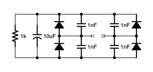
Still I wanted to keep the network as easy as possible- so I came to the solution shown, with one additional capacitor: C3 boosts the bass-frequencies - without it the low frequencies dropped too much (see simulation). The result is a simulated frequency response of ~0-40kHz(-3dB) with some +0,5db/-1,5dB variations.

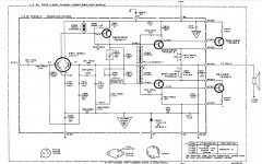
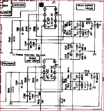
The RIAA network (series-resistance and parallel-capacitance of the inductors are not shown):
LCR-schem.PNG


Simulated Frequency response:
green: with C3
red: w/o C3
simLCR-RIAA.PNG


---
Next step: I made a board with two opamps and the RIAA network between them. Instead of the network I put a connector on the board, so I can easily switch between RC- and LCR- network (which were on a piggy back-board).
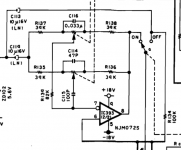
To serve the low impedance of the network, the first opamp is actually made of two in parallel (which also helps reducing the input-stage noise a bit- but this is a parameter, which I completely ignored in this test), see schematic below.

Parts used:
L1: Fastron L-07HCP 1,0M
L2: 3x Fastron L-11P 150M
L3: Fastron L-11P 150M
C3: 2x Wima MKS02 63V 3,3µF
all resistors 1% metal-film (selected channel-wise)
IC1: NE5534 (also tested: NJM 2068, LM4562)
IC2: NE5532 (also tested: OPA627)

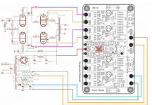
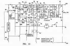
Schematic of preamp, LCR-network and rc-network:
preamp_schem.PNG


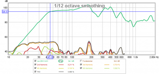
The Bode-Plot function of my Osci was not so good to visualize the deviations that came out in the simulation. Measured Frequency-Response with RC-RIAA:
measRC-RIAA50k.jpg


Measured Frequency-Response with LCR-RIAA:
measLCR-RIAA50k.jpg


Anyway, next thing was the hearing test:
First, this Preamp doesn’t sound bad at all! But unfortunately, I must disappoint those who were hoping that the cheap LCR network will be a revelation. Still, it is better by a small margin: instruments, voices are tad better separated, sound is a bit clearer, but it is a rather small difference compared to the RC-network. I wasn’t able to hear any differences in the frequency response, although the lowest bass should be somewhat lower with LCR network.
I have no possibility to make distortion measurements.

Remarks:
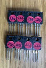
-although the inductors were 5% tolerance, all of them were within the 1% range. It was easy to pair two batches for left + right to better 0,5%
-bringing the inductors close together changes it’s inductivity. I didn’t consider this on my board, but the result was still good (within 1%)

Conclusion:
I have not really a conclusion for all this 😎
I have still some other phono-preamps that I want to build in the future and probably I will implement the 2122Hz pole with LC (150mH/2k).
I have already designed s split LCR-RIAA version of this, which should present a much more linear frequency-response but at present I have no time to build it.


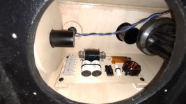
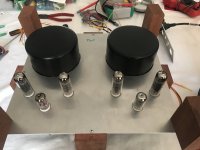
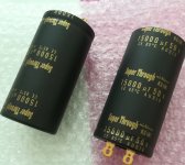
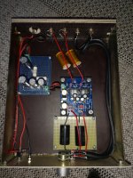
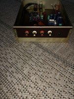
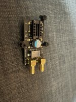
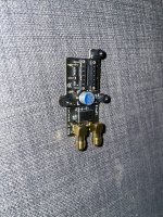
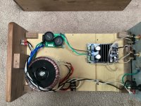
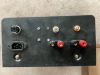
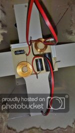
A pic of the boards:
board3.jpg


Cheers, Boris

FS: tpa3255 amplifier parts complete.

Two Shui Yuan Tpa-3255 boards, HPOO rectifiers, Antek AN-3225 transformers for sale. Plus rca inputs, speaker binding posts, power socket, fuse and holder(see picture of rear panel). In fact everything needed to build two great sounding stereo amplifiers except for the cabinets.
I assembled these a few months ago on an mfd board(picture) and ran various diy speakers and also my Quad 988s. They sounded so good that I planned to build a really nice pair of cabinets, but for various reasons that project is in the bin.
$120 plus $16 shipping by usps medium size priority box.
Peter

Attachments

  • 1A2C726D-804C-4981-9AD3-5854A96AE07A.jpeg
    1A2C726D-804C-4981-9AD3-5854A96AE07A.jpeg
    533.8 KB · Views: 135
  • E721B8F1-7477-4127-A14E-9AF6F0CFC774.jpeg
    E721B8F1-7477-4127-A14E-9AF6F0CFC774.jpeg
    350.8 KB · Views: 129
  • A949050B-D2A9-4C44-840B-40DB0478B58D.jpeg
    A949050B-D2A9-4C44-840B-40DB0478B58D.jpeg
    891.2 KB · Views: 131

Want to use op amp instead of ic in Tone Controller circuit..

Helo friends I I am building a op amp tone. Controller circuit but this circuit the ic is showen is not available here So I want to use tl072 op amp instead of this ic And Just Want to Know The Connection for Tl072 op amp can any one do it for me??
Thanks in advance..

Attachments

  • Screenshot_20220219-133504~2.png
    Screenshot_20220219-133504~2.png
    38.7 KB · Views: 152

Cheap/simple relay/resistors attenuator for RPI

Hi ,

we are developing a new shield for RPI that can work either as a stand alone or to be used with allo products (DACs)
We expect them to cost less than 65$

We are using thin film resistors 0.1%

I have attached the preliminary placement.

Attachments

Creek phono stage OBH-15 noise and PSU

I am in the process of re-vitalizing my LP playback equipment.
From eons ago I have an SME III arm and an Entre MC-1 moving coil cartridge.
I have recently picked up an AR turntable, so all I needed was a phono stage.
Not so easy!
There are many on the markets, some at silly prices, so recently I picked up a Creek OBH-15 for cheap, and gave it a quick test.
Wow - this thing is a bit noisy, quoted SNR is 75dB on moving coil input - I don't know about that, out of the box the noise envelope on the scope was about 2mV RMS. If that is 75dB down, we must be talking @11V output RMS! My unit's SNR was about 62dB by my calculation (@ 2.5V rms).
So I opened it up, replaced all signal pass-through caps from electrolytic to polystyrene, coupled all smoothing caps with more polystyrene, used copper tape to make a housing for the MC input stage, disconnected the MM section & the switch.
After this the noise envelope improved to 1.2mV RMS ( 4.5dB better).
Then I just hooked up two 9V batteries together and tested it again.
Noise level now is 0.7mV RMS (about 2mV peak to peak) another 4.5dB !
But that is not all, the nature of noise changed from a harsh background to a mild, even handed hash.
I am going to use cheap mobile phone batteries ( at £5 for five) and fit them inside the box, there is room in there, I just need to figure out an easy way to charge them up. a 900mA/h battery should run the circuit for about 25 hours.

I have not even heard it yet, I had to sort out the noise first.
Any ideas as how to go further ?

Tube and transformer proximity considerations

Hi there, thanks for coming by.

While I can probably figure this out myself, it would be nice to hear from those that have specifically done this.

I'm rounding up parts for a stereo tube amp build (60W per side, KT88's, 2 GZ34's and maybe 4 6SN7's).

My question is, are there any guidelines you would adhere to regarding proximity of tubes-to-tubes, transformers-transformers, and tubes-to-transformers. I'm sure I have not much to worry about as this is being build upon a 19" rackmount chassis and I can make the depth anything I want. I was thinking around 12 inches. That's a lot of room to spread things out. It would still be nice to hear from those though, that have found through experiment or mistakes, what the biggest perpetrators of unwanted electro-magnetic cross interferences have been so I could monopolize on those findings. Why not? I understand the positioning of PT and OT, angles and proximity but, I really don't know anything about GZ34 rectifiers and their risk of causing hum or noise in other elements/components. I would instinctually keep anything "input/preamp" away from anything "power related" or higher current output related but would just like to gather as much as possible before committing everything and drilling lots of holes,

This amp will be a Williamson type of amp, probably with a few things to increase stability and/or volume - that's to be seen, though.

Thank you,

Best,
Phil D.

Source for 2 conductor 14 gauge CLOTH covered cable

About to do some "upgrades" on my speaker cables. For both aesthetics and flexibility, I want to swap to "vintage" cloth braided lamp cord in light brown ( tan, light brown, even dark brown) All I can find in 14 or 12 gauge is 3 wire. Not as good for flexibility. Fine strands and rubber jackets add to flexibility.

I was thinking though, with no passive crossovers, even 18 gauge ( available) is probably measurably slightly better than my current 14 with the big chokes and caps. Doubtful any difference is audible at less than 10 feet. I many add a few feet so I can drop under the floor and avoid the curtains hanging up on them.

Just for grins, I went to see what Kimber was selling for these days. Many years ago I ran the 8T vinyl as I had an interference issue. It was quite reasonably priced. Now I see they are fully on board with extracts from squamates.

Recorder

Hi all
I am looking for any general suggestions or recommendations to implement a DIY recorder. Is this something better bought already made or can some be had with modules and such?

A recording and playback module would be nice, especially if there was a way to marry it to a USB interface. Trying to find some modular systems that can be integrated into DIY instrument amps

Turntable platter dampening?

While I'm eagerly waiting for the customized SL-1210MK2 to arrive and external power supply is nearly ready I apparently have too much time to think other stuff. So, platter.

We know that the platter it self in SL-1200's are "light" to put it mildly, and they do "ring" quite a lot. I would not like to have a thick (and ugly) rubber or APM or anything like that on the platter so I was thinking, why not put the dampening on the underside? There's for example bitum- or polyuretan-mats designed to reduce high-frequencies in panels and olaso reduce vibrations.

Any thoughts?

Denon PMA-2000R Intermittent No Sound to Speakers

This is an interesting sometimes works, sometimes won't.

When the amplifier is on the bench it works fantastic. I button it up and play it in my rack with no issues. 24 hours later, power on and hear the power relay kick in, red led blinking for a few seconds and then goes full red; but BOTH power relays are disengaged. I've tried a bit of bumping 😉 and no response. (repeat this paragraph 2-3 times 😱).

Take it back to the bench and see same issue. 😕 Decide to look at the protection board behind the bottom cover.

I turn the amplifier upside down remove the bottom to look at the protection board. It looks good with no noticeable issues, all capacitors are high quality caps with no bulges. Well, turn it on while upside down and low a behold it starts working. 🙂 Put back the bottom, flip back right side up and still working.

My diagnosis is there's a loose connection, but can't see it as this thing is solid with literally no loose wires, just connectors. Whatever the issue, it shuts down both channels and I don't think it's a relay.

Anyone seen this symptom on a PMA-2000R or PMA-2000IVR? Maybe they work better upside down?

Thanks!

SSE layout question

I populated this board long ago and got distracted by life. I’d like to finish it now. I’m considering layout options. I have the power transformer axis rotated 90 degrees to the OTs, as one does, but I’m wondering where I should place the choke so as to minimize hum. In the photo I have the choke with its axis aligned to the PTs and pretty close to the OT. The small anodized transformer will go underneath the chassis and I could place the choke in its place, perhaps with its axis rotated 90 to the PT.

Any advice would be appreciated.
477D06FF-324C-4BF6-AF6D-9E0B73C85590.jpeg

recapping my beloved old speakers

Hi everyone,
I'd love to get advice on which caps to get to replace the ones in my RSC santa maria II. Not an expensive set of speakers but they sound amazing to me.
Since they are now approaching 40yo.. thinking recapping them would possibly get even better sound out of them..

from what I can see there are 3 caps per speaker
2x Callins CXPSD4-50NP 50V NP
1x Shizuki 6.8u FM50

What would you replace them with ?

Cheers!

Hifonics Brutus BRZ1200.1D

When this type 7 amp came to me, it undoubtedly had had a reverse polarity issue. One of the reverse protection diodes (D2) was blown apart and it was showing a short from battery(+) to ground. Replacing the diode fixed the short. On power-up the amp went into protection. In checking, I removed the outputs (IRF640Ns) and the output driver card. I traced the protection issue down to the over-current transistor (Q283) testing bad. While waiting for my order of transistors to come in, I went ahead and replaced the 3 each PD2 transistors(U1, U2 and U3), 2 each 1D transistors (Q5 and Q7) and the 2 TL072 op amps (U4 and U13) for good measure.
After replacing Q283 and checking the PS, I reassembled the output section and everything looked good on the oscilloscope. I mounted it back into the heatsink and connected a woofer and music input. The amp maxed out and the supply voltage dropped. The woofer sounded "muffled" and had a lot of static. I connected my larger power supply and removed the current limiter. It did the same thing (the amps only got up to about 8A. I wasn't really pushing it).
I removed the amp from the heatsink to do more tests. I used 13.8vdc supply limited to 4.5A. My signal input (when used) was 50Hz at 2vpp. These voltage readings are referenced to the (-) speaker terminal. I also tried referencing the battery ground and got the same results.
With no signal input, I found that I had -3.42vdc across the speaker terminals when the relay clicked on. I traced that voltage back to the low side drains and the high side source legs of the outputs. The voltage appears when the remote is turned on.
When I input my signal, there was -2.5vdc on the the low side drain legs and high side source legs. When the relay clicked on, I had the -2.5vdc across the speaker terminals. When I removed the remote, the voltage across the speaker terminals went to -58.9vdc. I checked this seven more times. The voltage readings I got were 12.31, 33.2, -3.32, -58, 58.2, -59.2 and -32.4. These spikes only show up on the speaker side of the relay.
when I connect a speaker ( I tried non-inductive loads, too), I get 6vdc across the speaker terminals, the 4.5A power supply maxes out and the supply voltage drops to 9.3vdc The voltage does not spike when the remote is removed. The signal at the speaker terminals on the scope looks like a half rectified sine wave with the crest chopped off.
I am running out of ideas other than to put all new outputs in just trying to make it do something different,

Yamaha A-1 Revamp

Hi all,

Had come across a very fair deal for a Yamaha A-1 integrated amplifier recently, picked it up, and it is in absolute mint condition with barely any internal dust. Sounds great, however ~feels~ like it is missing a bit of low end punch. With that, it is actually the first amp that seems to bring out great detail in murky basslines. Thus the quandary… does it really need to be touched?

I’ll be checking all the test points shortly to make sure things are in spec voltage-wise, but have been scope-less for a while and won’t be able to do any extensive probing. The capacitors show no visible sign of any bulging, but since it is now a 30-year old amp, I’m sure the majority of responses will be to replace all the electrolytics.

If I do get the itch to start upgrading the odd bits, here’s what I’ve figured so far…

Superficial:
- Replace original flimsy 18AWG power cord with something more substantial (or install an IEC socket)
- Replace speaker posts with gold-plated multi-way binding posts (easy to make a mounting plate)
- Replace lamps with white LEDs (looks like a 12v AC lamp supply)
- Replace headphone jack with something of higher quality (seems to be a bit of static/DC when connecting; will recheck after making sure test values are in range)

Electronic:
- Recap main smoothing caps (original are 10,000/63v) If they can actually fit, would Pocoyo’s 12,000uf Elna be an OK replacement without putting any additional strain on the rectifiers, or transformer secondaries?
- Recap the rest of the PSU regulation board with Panasonic FC (Original are Nippon Chemicon)
- Replace the VD1212 diodes with 1N4148 (as discovered from an Audiokarma thread)
- I have a question about TP1 (-35.09 looks like the test voltage reading? Am I wrong? Schematic will be necessary.)
- Anything else…?

I did get the original manual, which has a beautiful micro-printed schematic. For those who would like a copy, leave me your email address. I’m not sure at what quality I can get it to you, as the 600dpi scan is ~80MB. I’ll keep working on the best way to trim it down, as all the captioning is microscopic. Pictures of the guts will also be posted as soon as I can manage.

I’m still an absolute amateur with more of an electro-mechanical skillset, but can reasonably follow how things work. My M-80 revamp was enjoyable, so hope to keep the momentum of success. Don’t want to risk anything drastic, but would enjoy bringing it back to peak performance if necessary. Any and all insight is always appreciated.


Cheers.
:flame:

resonance induced street pole shake?

I live in San Diego, California. I noticed a street pole shakes near my home, apparently for several months. I put up a video here: Login to view embedded media Apparently leading theory seems to be acoustic in nature, for last several months shake had been more apparent. With rare rain here (drizzle today), I noticed the shake is very minimal. For acoustic engeneers is this sound/traffic noise induced street pole shaking?

Replace optical with infrared?

Hello all,

I think about replacing my optical cable that runs over whole room with IR transmission. Has anyone tried it? I think it should be easy with existing circuits: SPDIF to TTL converter, TTL to IR converter, IR to TTL converter, TTL to SPDIF (COAX) converter. It all should exist, right? Some wireless headsets use IR as well (but not that I want, I guess they use lower carrier frequency)

Thanks, Jan

Holton Audio (NEW!) NXL102 R1 Stereo Power Amplifier Module

Here is a new stereo power amplifier module on offer from Holton Audio.
It features 2 pairs of Exicon ECW20N20, ECW20P20 Dual Die Lateral MOSFETs with on-board power supply of 4 x 10,000uf 63v filter capacitors and fast recovery 20 amp continuous bridge rectifier.

NXL102 R1 Amp 3D Model-2.PNG


Specifications:

Stereo, 8 Ohms:
150W RMS per channel

Stereo, 4 Ohms: 260W RMS per channel

Frequency Response: 20Hz-20Khz, -0.1db, 3Hz-170KHz, -3dB Input filter limited.

THD: 0.005%, 20Hz-20KHz, @90W RMS into 8 ohms

IMD: 0.005%, @100W RMS into 8 ohms

SNR: -118dB, Unweighted, referenced to full output; -123dB Weighted

Damping Factor: 800 into 8 ohms, 100Hz

Gain: 22 (27dB) other gain options are available upon request?

Input Impedance: 20k Ohms Unbalanced: 40K Ohms Balanced

Crosstalk: 100dB, 20-20kHz

Inputs: XLR Balanced or RCA Phono

Recommended Linear Voltage Supply +-63 volts DC
PSU Power Transformer secondary windings 45vac (800VA)
Printed Circuit Board Dimensions 210mm x 84mm
  • Like
Reactions: vacuphile

Crossover network for EV 8L and P Audio PHT-407

Hi!

Im using some components Ive got to reload a burnt out Powerworks RS 82 PA top cabinette.

What crossover frequency should be used, and - if possible - could I get some help with getting the values and schematic of the needed components?
Running a mac at the moment and there aren't a whole lot of crossover software, should Ive known how to use them... I saw the great guide here though, and will read into that.

The woofer is the EV 8L found here: https://www.thomann.de/se/ev_8_speaker_type_560459100.htm
Tweeter is the PHT-407 found here: http://paudio.co.uk/products/P-Audio_PHT-407_15W_Compression_Driver_With_Horn.php

Woofer: 8ohm, 91.2 db
Tweeter: 8ohm, 98 db

While the specifications are to be found on the links above, I will of course post whatever values needed - I just don't know where to start.

The box is what it is. While I'm hoping for at least some low end, it is originally designed to be used with a subwoofer. Maybe we shouldn't expect miracles though - so lets focus on a smooth midrange 🙂

Best regards, Björn

Bose L1 compact repair. SMPS IC keeps blowing

Hey Folks,
I've recently got a Bose L1 compact sound system in for repair. The unit failed to power up one fine day.
After opening the unit up the first thing I noticed was the TOP258 IC was cracked open. Before replacing the IC I had a look for any other components which might have failed. I checked for the obvious culprits and I couldn't find anything which has failed. I checked the diodes and resistors around the IC, checked the main filter caps and the electrolytics near the IC. Checked the secondary side for any shorts or failed caps and nothing. I checked the capacitors with the ESR meter, I removed some capacitors and checked them with my multimeter for the capacitance value as well.
So after much contemplation, I decided to change the IC only but the thing was I couldn't get hold of any TOP258 ICs. So I placed order for those. However I had TOP256 IC in my parts bin. It can handle low power than the 258 and to see if anything else failed I replaced it with it (until I got the 258). Powered it up and it was working. Obviously I didn't run it at full volume or had it on for long.
After week of intermittently testing again the unit stopped powering up. Opened it up the SMPS IC was cracked open. Same story as before nothing else seems to have failed. I now have got the TOP258 IC but am afraid the same thing would happen unless I could find the culprit.
I have checked the speakers thinking they might have partly shorted and might have been drawing too much current. They also test out ok. The amplifier IC is TDA8920B. On the datasheet the amp chip and the TOP258 seems to have all the protection in the world and seems to be bullet proof.
I was hoping someone could shed some light on how to proceed and what else to look for.
I have attached a pdf of the power supply schematic.
For a while I was pretty sure that the TVS diode (DZ1) might have failed as that would put high voltage on the drain pin, but it shows forward voltage of 0.6 and doesn't show anything in the reverse direction. I'm not sure how I can check it for proper 'TVS' operation.
The full schematic can be found BOSE L1 COMPACT SYSTEM SERVICE MANUAL Service Manual download, schematics, eeprom, repair info for electronics experts

Thanks in advance.
P.S: I have got another unit which came in for repairs and the capacitor and the resistor of the LPF was burned up and bulged on that one. The SMPS IC was cracked open on that one as well. I also checked those components on the unit I'm currently working on and they test out ok.

Attachments

Replacement volume pot for McIntosh C26

I'm working on a McIntosh C26 and the original volume pot is shot. (resistive contact surface is half gone)
The volume pot has the power switch built in.
There's a reproduction available on ebay but it is very expensive for what it is (and I've used his parts before and they haven't been as balanced as claimed). I'm thinking it would be better to get a decent quality volume pot and just use a power conditioner to switch the entire system.
It doesn't have a loudness tap, so that makes it easier. But it is a 500k pot, and I'm having trouble finding that value.

Any suggestions?

what db to hit

When modeling enclosures, what db would be considered very good? when i model using hornresp i may be lucky to get up to 95 or 100 db. Is this going to be a loud box? I can model a 6th order enclosure in term lab pro and it show me db around 130. Is there a different scale in hornresp? What is the goal? I dont want to waste time building an enclosure and then it not be as loud or louder than what i can easily already make.

Bile Duct Amplifiers

I found a couple of things for sale that made me laugh pretty hard so I want to share this with the community. I hope you get a laugh too. Its holiday season here so let's go with this.

The first is the "Dual Vacuum Tube Bile Duct Earphone Amplifier".
Apparently it gets a one thumb up rating according to the picture.
Screen Shot 2021-11-24 at 5.07.06 PM.png

The next is the "bile duct tube pre-stage fever pre-amplifier" on Ebay.
They have the pre-amp with the fever and it's still a bile duct amplifier.
Screen Shot 2021-11-24 at 5.06.45 PM.png

3 way PA

This is my latest project.
I wanted something that sounded better than 15 inch fullrange speaker on a stand.
So i decided on a 2.2 sound system.
Having already two large 18 inch subs i wanted something more portable, something that can be carried by one person, could still be called a subwoofer and not have problems filling large rooms.
That's why a chose a 15 inch driver (15NW100) in a box very similar to B&C Sub15. The final box has 110 liters and it's tuned to 42 hz (without any filling) with a 400 square cm port .

As for a midtop i chose an 8 inch (8NDL64) and 1 inch compression driver (DE250) on a Eminemce horn (H290) that i had to cut its sides so the width of the enclosure not get too wide.

Enclosure size is about 15 liters and it's tuned to 65 hz with a port on the back. Crossover point between the midbas and the de compression driver is at 1.6 khz second order.

The sound is exactly what i wanted.
The subs go fairly low, good enough for DNB, Dub and Dubstep with a fast and punchy kick.
I feel like these drivers can eat a lot of power, a lot more than what a TSA 4-1300 can provide.
The tops sound crisp. The midtop has kick and the midrange is clean and warm. The compression driver horn combo i've used in the past and i am still impressed by how it sounds. It has enough spl/power to be pushed to high levels, while still retaining a crisp sound. I am still at the first version of the crossover with minor tweaks to come.

Attachments

  • IMG_20210530_004841.jpg
    IMG_20210530_004841.jpg
    191.5 KB · Views: 219
  • IMG_20210531_094230.jpg
    IMG_20210531_094230.jpg
    248.9 KB · Views: 187
  • IMG_20210601_185937.jpg
    IMG_20210601_185937.jpg
    229.3 KB · Views: 189
  • IMG_20210601_185944.jpg
    IMG_20210601_185944.jpg
    175.1 KB · Views: 200
  • IMG_20210602_232716.jpg
    IMG_20210602_232716.jpg
    232.6 KB · Views: 205
  • IMG_20210602_214842.jpg
    IMG_20210602_214842.jpg
    184.8 KB · Views: 224
  • IMG_20210603_190359.jpg
    IMG_20210603_190359.jpg
    201.1 KB · Views: 230
  • IMG_20210604_231436.jpg
    IMG_20210604_231436.jpg
    203.4 KB · Views: 224
  • IMG_20210607_090425.jpg
    IMG_20210607_090425.jpg
    377.3 KB · Views: 232
  • IMG_20210609_180233.jpg
    IMG_20210609_180233.jpg
    406.3 KB · Views: 230
  • IMG_20210820_201721.jpg
    IMG_20210820_201721.jpg
    611.5 KB · Views: 221
  • IMG_20210820_204101.jpg
    IMG_20210820_204101.jpg
    314.2 KB · Views: 228
  • IMG_20210820_204105.jpg
    IMG_20210820_204105.jpg
    295.4 KB · Views: 253
  • IMG_20210905_165345.jpg
    IMG_20210905_165345.jpg
    675.8 KB · Views: 225
  • IMG_20210905_164251.jpg
    IMG_20210905_164251.jpg
    671.8 KB · Views: 237
  • IMG_20210905_164245.jpg
    IMG_20210905_164245.jpg
    532.3 KB · Views: 219
  • IMG_20210905_171348.jpg
    IMG_20210905_171348.jpg
    467.7 KB · Views: 295
  • Like
Reactions: TroelsM and pelanj

Crossover Help for Microbes

I have absolutely no experience designing speakers though I have successfully built a few kits. Just looking at software for designing crossovers has left me completely intimidated. Kinda wishing I hadn't bought the drivers now, however I really do enjoy building the cabinets. Anyway, I am looking for help reworking the crossover for the Microbes, originally designed by Roman Bednarek ( https://www.rjbaudio.com/Microbe/microbe.html) and modified by Dave Zachary ( https://www.rjbaudio.com/Microbe/Reference_Series_Microbes_v3.pdf ). I have the original Dayton RS125AS-4 woofers but the RS28AS-8 tweeters are no longer available and I have purchased the Dayton RST28A-4 tweeters. These tweeters are slightly more efficient than the RS28AS-8 and have a bit higher of an impedance peak. I can post links for the specs if required. I would like to build two pair, one pair will hang directly on the wall so the baffle step compensation from the original design will not (?) be needed for that pair. Thanks in advance for any help.
Dan

Leaving my Threshold 4000 on 24/7?

I have a Threshold 4000. Fairly recent purchase.
is it ok to leave it on 24/7 while turning off on the few occasions when I’m away from home for extended periods of time?

I have a Furman power conditioner and surge protector.
ive read an article about a 400a saying it can improve sonics with leaving a class A amp on.
I have a Threshold Fet2 preamp.

I’m curious if there is any articles or documents from Nelson himself on this topic?
I know first hand the stasis can idle and stay powered on with no issue what so ever. My fathers has been on for 4-5 years only turning off on few and far between occasions.

Mixing IRFP240's from different lot codes for Aleph J

The IFRP240's are hard to find right now. I need 8 of them for my Aleph J build. I have enough matched (Vgs) within 0.1 volt, but they're don't have the same lot code. Is there an issue using different lot codes together in the same channel?

I also have some 240's that have about 100 hours on them. Can these be mixed in with new devices? How about one channel new devices, one with used? The new and the used have different lot codes.

Pair of Acoustic Elegance IB15HT on Ebay

I am selling a pair of used AE IB15HT on Ebay they have been used a few years but are in good shape.
https://www.ebay.com/usr/bushinski
I tried to sell them installed in my dipole "enclosure" but don't think I'll have luck since it's bulky. So I might be interested in selling the enclosure separate.
https://www.diyaudio.com/community/threads/corner-dipole-subwoofer-for-sale-in-minnesota.383004/
Projects by fanatics, for fanatics
Get answers and advice for everyone wanting to learn the art of audio.
Join the Community
507,753
Members
7,886,666
Messages

Filter

Forum Statistics

Threads
406,157
Messages
7,886,666
Members
507,753
Latest member
ayodej