Combining EF and CFP output stage

Hi Guys,
I am interested in designing an output stage to mitigate some of the high frequency crossover issues with the CFP topology. I have heard some mention of combining the CFP in parallel with an emitter follower stage.

Has anyone here used this in an amplifier before, how did you bias each pair of transistors and where there problems with one pair doing all of the work.
What are the best practices for designing with this stage?

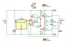
I don't really know what I am doing but after some trial and error this is the general concept that I came up with.

cfp and ef output stage.png


I am hoping that this thread will lead to some interesting discussion, and if this has been talked about somewhere before please let me know.

Alex

Peak Voltage Detector

I was planning to use the peak detector described on the Elliot Sounds website:
https://sound-au.com/appnotes/an014.htmSpecifically this one:

an014-f3.gif

However while simulating its response I noticed the maximum peak is limited by VCC/2, can anyone explain this to me?
The circuit in figure 2 is also showing as limited to VCC/2.

How could I alter this circuit to alter this response?
I have +/-5V and I'd like the peak detector to work from 20mV to 3V3 (3V is also acceptable).

I've also tried https://www.analog.com/en/technical-articles/ltc6244-high-speed-peak-detector.html but it is unable to monitor low voltages.

Resizing an image moves the page scroll

When I insert an image into a post, resizing using the image handle results in the web page scroll bar moving also.

To test:

Raise a new thread,
Insert an image,
Click off the image then click the image to get the resizing handles,
Grab the bottom right resizing handle with the mouse and drag,
-What I see is the web page scroll bar on the right hand side of the screen moves with the mouse motion.

Windows 10, Chrome, Logged in, Incognito and normal.

AUDIO XPRESS has been sold to Elektor

Fyi, and all that, I received an email from the marketing people at Audio Xpress, all of the publications have been sold to Elektor US.

I presume that this means that Ed Dell is either retiring or ill, I have no idea, but he is done with the mags.

Ed Dell certainly did a great thing for DIYers in the USA and around the world by starting Audio Amateur Magazine. For that I thank him...

_-_-bear

Active Sub + 3 Way Satellites with high order LR8 acoustic and BW 6 or BW 7 electrical filter

High all!
I am testing a lot this here:
IMG_0460-resized-rotated.jpg

and this here:
IMG_0448.JPG

the first idea to use this speaker chassis came from here:
Troels Gravensen The Loudspeaker II
I have made a lot of listening tests with acoustical LR2 LR4 and LR8 filters and stay now with LR8 - a little bit like what the guys from Gauder Akustik in Germany is doing:
Gauder Acoustic English Web Site under construction...
But of course not with high order passive crossovers, very difficult to develop, with miniDSP and a lot of listening tests for hobby diy audio doable.
Crossover frequencies:
SUB - bass mid woofer 150 Hz
bass mid - mid high horn 1200 Hz
mid high - super tweeter 7000 Hz

Transformer for a European Amplifier

I bought a 240V european amplifier (Ayon Spark Delta). As many of you know, there is a difference between US 240V and EU 240V. The US system has two 120V legs, out of phase with each other so that they measure 240V between legs. In europe they have a single hot leg that is 240V to ground (or neutral).

Some european amps will run just fine on the US system. However, my Ayon won't. It has a phase sensing circuit and expects to see a 0V leg and a 240V leg.

So I bought a transformer to step up the us 120 volt electricity (0V leg and 120V leg) to 240V. I expected to see the output legs to be 0V to ground and 240 to ground, just as in Europe. It even has European outlets on the front of it.

However, the output was 2 legs of 120V out of phase. I don't even know how it did this easily. It is a wound copper transformer (not SS).

My question is, how do I buy a transformer that will give me the EU standard (preferably something I can buy on Amazon to get this amp making music while I shop for a high quality transformer).

Jerry

Discrete Preamp Troubleshooting

I'm running into some stability problems with this preamp I'm building, and I'm wondering if anyone could give me some pointers on how to troubleshoot it.

When I first power it up, the output consistently goes to 20V DC. If I briefly short the output to ground, it will drop to zero and perform normally for awhile. If I don't do anything, it may eventually drop to zero, but it is inconsistent, and it may jump back to 20V DC and stay there. When it is performing normally, I was measuring about 0.02% THD at 1khz with a 5V output. I had it hooked up to my scope, and could get a clean looking 1khz sine wave, but it would eventually get stuck back at 20V as I increased the frequency to 10khz. I'm not sure if what I'm running into would be considered oscillation, or something else, because it just looks like DC on the output.

For background, I'm building this to drive a couple different single-stage amplifiers I built. One is just a follower, which is why this preamp is configured for 26dB of gain. I wanted a circuit that I could configure for anything between 6dB and 26dB. The goal of this particular circuit was to make it as simple as possible. I also have another PCB where I added input degeneration, a current mirror, and a buffered VAS, and I wanted to compare the difference between the two versions.

A couple things I'm wondering about:

- The current source configuration is rather simplistic, and there isn't anything to slow down or sequence the startup of the three current sources. I'm wondering if this is the source of my problem.

- I originally selected R2 to balance the current through both legs of my LTP in my spice simulation, but when I actually built the circuit I found that the voltage drop across the two resistors is rather uneven, so I think I need to go back and make an adjustment.

- I'm wondering if there is a "guess and test" method to selecting a value for C2 that works. I realize that this is something to be calculated, but all the math is a little bit beyond my level of understanding. I originally started out with a smaller value, but I noticed that I was seeing fluctuations in my THD measurements when I poked around with my finger, so I interpreted that as a sign of instability and kept increasing the value until it went away.


Discrete Preamp.png


IMG_3338.jpg

Attachments

Dual Kicker Hideaway install/setup

Hi there. I was hoping someone could help... I’ve had and was happy with the kicker hideaway 8” for almost a year now. Simple install. Decent sound.

I recently just got a deal on the hideaway 10”.

I unplugged the 8” and plugged the harness into the 10” under the driver seat and its just absolutely incredible. Crazy improvement, much more than I could have expected.

But now I want the 8” under the passenger seat.
My question is how is the dual setup recommended? Can I just tap into the wiring from the already installed hideaway
or
do I have to run all new wires to the head unit and another (2nd) the fuse line holder to the battery for the (2nd) hideaway?

Really hoping I could just splice into the wires already ran to the head unit and the battery... anyone know if is this even possible? Or how a dual kicker hideaway setup should go....

I’m not an expert. But I did install all the below on my own. I’m just unsure to to add to this.
If that makes no sense see below:
Setup in my Jeep
Alpine ILXW650 head unit (with piggy back alpine amp)
Kicker 6.5 x 4
Kicker 3.5 x 4

Kicker hideaway 10” sub (has own amp)
Fuse line holder to battery
Blue power to head unit
Speaker wire to RCA’s to head unit
Ground.

Simple.

Wanting to add - but not sure how? All new wires and setup? Or splice into current hideaway wires that are already ran?
Kicker hideaway 8” sub (has own sub)

Static/glitch? noise that doesn't increase with volume

Hi. I've just replaced all the electros and bias a Pioneer SA408. Nice little amp from late 70'.

There's a noise. It has two layers: an almost continuous "ptz" and another glitchy sound that comes in like every 2 seconds. Sometimes other artifacts can be heard. The noise is above the hum at the background. At night or at quiet moments it's annoying. That noise stays at the same level no matter the volume. The loudness and other switches don't affect it either. The bass & treble pots do affect it. At least, that's how it sounds like. I'm going to make some recordings. This noise was before all the recap and such, but I've always thought that it was due to aged components or so.

Cheers!

Wiring signal input

I'm re-wiring the input on my amplifier and I figured I should ask your opinion on which way to do it best, to avoid ground loop etc.
This is two single RCA inputs that's going to a DSP with one ground and two positive on the connector.
So there's two positive and two negative at the chassi in, two positive and one negative at the DSP connector.
The cable I bought has two conductors and a shield (with wire).
If I use one cable I would have to use the shield as ground, and I'm guessing that it could pick up interference (that the shield is meant to protect from).
Or I could use two cables (where I let the shield alone) and either:
1. Use just 3 out of the 4 wires, just use a short wire at the chassi input to connect the two negative.
2. Use all 4 wires and connect the two ground wires at the DSP connector.

This is a very short distance, but the whole ground loop thing seems to be an interesting phenomena that I don't fully grasp. 😂

Driving a capacitive load with a tube

Dear people,

When I am driving a capacitive load ( cable), does this means that the reactance of the capacitor is in parallel with the input impedance of the stage it feeds?

If this is the case then driving 15 meters ( 49.2 feet) of for example Belden 8412 gives 2850 pF. At 20kHz this has 2.79K Ohm of reactance.
Driving a 470 K Ohm input this would be 2.77 K Ohm total load. This would be very difficult to drive for a tube wouldn't it?

Are there any tricks that help tubes deal with capacitive loads?

Thanks and kind regards

Neurochrome Modulus 86 V3 For sale

I have up for sale my Neurochrome Modulus 86 v3 stereo amplifier. I used all the recommended components - no substitutions (I had to source parts from 9 different vendors). It's all in Neurochrome's custom built chassis and uses the Antek power supply. High quality wire and solder was used.

I purchased and installed the Speakon connectors and the 12v trigger, but those are not wired up.

Asking just what I paid for the parts and components - $1200 plus shipping.

Any questions, please email me at brian.terreau@gmail.com

Thanks!

Attachments

  • 20220305_130100.jpg
    20220305_130100.jpg
    477.6 KB · Views: 372
  • 20220305_130106.jpg
    20220305_130106.jpg
    401.9 KB · Views: 452
  • 20220305_130112.jpg
    20220305_130112.jpg
    409.1 KB · Views: 616
  • 20220305_130254.jpg
    20220305_130254.jpg
    294.4 KB · Views: 360
  • 20220305_130302.jpg
    20220305_130302.jpg
    358.7 KB · Views: 367
  • Like
Reactions: stretchneck

Over powering a small sub - how bad is it?

Recently my KLH 8" powered sub had a heart attack and the amplifier board is now dead. It seems one of the springs from the spring terminals popped loose on the inside, landed somewhere it shouldn't have, and now there is a large brown, burned spot on the amplification board. RIP.

I have a Dayton Audio SD215A-88 that I got from someone else's failed attempt to repair or upgrade a different powered subwoofer. I also have a two channel receiver collecting dust. What I would like to do is put the Dayton speaker in the KLH enclosure and power the Dayton with the two channel receiver. Since the Dayton sub is dual voice coil, I can power it with both channels of the receiver. I would have to split the subwoofer output from my 7.1 receiver and connect it to the two channel receivers CD or Aux input, and then use the two channel receivers volume as a gain for the (now passive) subwoofer.

In theory this should work fine, I've read about others doing the exact same thing on many forums. The problem that I'm concerned about is that the Dayton speaker is only rated at 80w RMS total, so 40w RMS per coil (dual 8ohm coils), while the two channel receiver is rated at 100w per channel. I've also read that overpowering speakers is much better (or less bad) than under powering them, but I'm concerned when it's 150% over the rated power handling. I'd like to hear some opinions or feedback on this idea.

PS: I'm not really interested in spending any money on this since I'd prefer to put money towards a larger sub instead of a Frankensub. If I can make this work for a while then I can save up to buy or build something better, eventually.

variuos Pass Labs based PCB(~30psc) XA.5, aleph-X, Aleph5, F-5,some stuffed.

I have stumbled on box in my workshop when did spring cleaning . Pass Labs or related stuff. most of them were prototpypes assembled to measure and listen (with resistors which I had on hand-so messy work)- before final assemblies ( which were made on new pcb, so those were “forgotten” for years)

Someone with basics skill can desolder and solder components more nicely ar leave as is and enjoy them rather than collecting dust. there is also used matched power mosfets if needed.


1) Aleph –x (Grey Rollins version) from 2007 one build with dale cfm-55. were working maybe some small parts missing matched irfp 044 and vishay 240 can be included
2) XA.5 based project from ~2014 , some changes were made comparing to original units ( like biasing circuits- termostablisation implemented with mosfet instead of thermistor) I can provide schematics with parts with condition not publish it. total 3 channels of complete amp (with reduced mosfets to 16psc to target more current per fet and 2psc main /driver board , 6 powerboards.
3) XA.5 based project from 2012 with stock bias circuit . 4 channels.one unansembled I should have somewhere parts schematics for it
4) aleph 5 3 chanels from ~2003. pcb condition is poor some pcb tracks are damaged.
5) first wat f5 pcb 2 chanels . should have schematics somewhere but its so simple that it could be assembled with oficial f5 schematics
6) XA.5 project from 2015, same as 2) just newer/better revision pcb. 4psc new+2 pcb new but already soldered most resistors

Attachments

  • DSC_1760.jpg
    DSC_1760.jpg
    473.1 KB · Views: 209
  • DSC_1761.jpg
    DSC_1761.jpg
    450.8 KB · Views: 197
  • DSC_1763.jpg
    DSC_1763.jpg
    606.6 KB · Views: 190
  • DSC_1764.jpg
    DSC_1764.jpg
    472.2 KB · Views: 215
  • DSC_1765.jpg
    DSC_1765.jpg
    442.6 KB · Views: 213
  • DSC_1768.jpg
    DSC_1768.jpg
    343.7 KB · Views: 201
  • DSC_1769.jpg
    DSC_1769.jpg
    323.4 KB · Views: 190
  • DSC_1770.jpg
    DSC_1770.jpg
    359.2 KB · Views: 201
  • DSC_1771.jpg
    DSC_1771.jpg
    485.3 KB · Views: 214
  • Like
Reactions: Mikerodrig27

Siglent SPD3303C Needs fix for 1 channel not floating

I bought 2 Siglent SPD3303C power supplies and one of them has a channel 2 that is not floating( - is tied to chassis ground). I did find one reference to another person that had the same issue and Siglent fixed it since both channels of the supply are supposed to float.
I contacted Siglent and I can return it but seems like I have to pay shipping at least 1 way across the US.
My question is, has anyone else seen this and can I fix it easily myself? Thx for any help.

Tweeter size: larger vs. smaller radiating area

I'm in the process of selecting drivers for a floorstanding 3-way speaker with an 8" bass, 4" mid and some tweeter. As for the tweeter I'm unsure what to use. I have two candidates in particular, because I already have them on hand. It's the Peerless XT25BG60 (1" ring radiator) and the SB Acoustics SB19ST (3/4" dome). My mids (Dayton RS125) are quite well behaved as far as cone breakup is concerned, so I don't have to cross too low.

In general smaller domes tend to have better off axis behavior, but need to be crossed somewhat higher to avoid excessive distortion. I haven't heard the SB19ST play yet, nor did I find many posts about it on various forums. Also, some favor larger tweeters over smaller ones, like Troels Gravesen. The XT25BG60 is a generally well regarded tweeter, yet also known for it's relatively bad off axis response. For aesthetic reasons I don't want to toe-in the speakers, even though my listening position is relatively close to the speakers (at an angle of about 30 degrees).

Which one would you use? Other recommendations are also welcome.

Virtual Ground Circuit: Which OpAmp to Choose?

Hi,

I am planning to build a virtual ground circuit as attached.
Now, the OpAmps that I have at hand are NE5534 and OP77. And I am really not sure, which one to prefer: The NE5534 is better at noise, the OP77 is better at bias current and PSRR/CMRR.
Can anybody give me a hint what the critical values are in this case? I really don't know 😢

Thank you!!

Attachments

  • Virtual_Ground.jpg
    Virtual_Ground.jpg
    29.9 KB · Views: 852

Source follower designs for a tube preamp?

Can I pick your collective brains for source follower designs for a simple tube preamp/driver stage?

I already know of Ale Moglia's source follower, which is one I will look at, but I would like to collect a variety of designs which offer a lower output impedance. I've seen simple designs with LND150 or other devices for instance.

The specimen tube stage is an ECC40, mu of around 30, with a B+ of 300v. Could be any similar triode. The goal would be a design that sounds as transparent as possible.

Any schematics or observations would be most welcome!


ECC40 resistor.png

Hermes-BBB/Botic cape for BeagleBone Black

Hi Folks,

The module/PCB is available here:
Cronus Reclocking

As promised here is more info on the Hermes-BBB for the Botic driver - it is part of an idea that Miero and I worked together to bring to fruition. Miero wrote the Linux driver/distro side and I worked on the hardware. Together we worked through the datasheets to decide how Botic should work. I am very thankful for the chance to work with Miero on this. It has been great fun.

Hermes-BBB is an open design. I will be sharing the design info (including gerbers etc) as soon as we figure out the logistics and licenses.

Here are some of the features:

  • Designed specifically to work with the Cronus - but can work with any other selectable clock source.
  • Exposes an isolated clock select output and master clock input.
  • Fully isolated audio signal with 1 -8 channels of PCM - 1 - 4 channels of DSD output. All I/O to the Cronus and/or DAC is fully isolated.
  • SPDIF output is possible.
  • Header for Switches/Rotary encoder
  • Header and drivers for indicator LEDs. These can be re-purposed for GPIO via the "FLAGS" header.
  • Auto selection of DSD vs PCM routing for DACs that multiplex the LRCK signal with a DSD channel. This means it works well with the BIII-B3SE etc.
  • Fully isolated and non-isolated access to I2C for interacting with DACs and other devices.
  • Jumpers for either powering the clean side of the I2C isolator from the Cronus or the DAC.
  • USART header
  • ADC header for analog control.
  • Headers for external power/reset switches.
  • Prototyping area (for fun!)
  • Provision for backup battery to protect the BBB on shutdown by providing a soft shutdown(self regulating battery not included in the kit - but very easy/cheap to obtain).

This module is one of a few Hermes module we have designed to connect directly to a Cronus module which provides the master clock and relocks the audio data to remove any phase noise.

It has been thoroughly tested and works with any audio signal which the BBB can generate. I have tested up to 384Khz 32-bit PCM. Similar data rates for DSD would be no problem.

The isolators can handle input and output in excess of 100Mhz without any issues.

We will be writing a comprehensive setup guide/manual.

It is designed to mate directly with with BBB and the Cronus for excellent signal integrity and no wiring mess.

This work is licensed under a Creative Commons Attribution-NonCommercial-ShareAlike 4.0 International License

Battery Selection

The Hermes comes with a 10K resistor across the NTC terminals for batteries that are self protected against overcharging/current/discharging - LiPo type "062535" (search ebay) are suggested. 250-500ma is more than adequate. This is the only type of battery we recommend!!!

It is possible to use other battery types - but it is not suggested - because the battery manager on the BBB does not protect from undervoltage nor accidental shorts (over current).

Cheers!
Russ

Attachments

  • hermes-bbb.jpg
    hermes-bbb.jpg
    54.2 KB · Views: 5,110

Scope with no AC mode?

So, my old Tektronix died. Don't need 100Mhz for audio, but storage would be handy. Bought a Hantek 6022 20 Mhz USB interface.
NO AC MODE! Unbelievable. I see there are hacks to convert to AC only, and one could stuff a big cap in the probe, but this is just plain stupid. I knew it did not have a separate external trigger.
Glad it was Amazon, as it goes right back.

Short of buying another real scope, do any on these USB boxes have AC and DC modes? I would never have dreamed no AC mode.

LED Bias in a CCS

I lifted this image off Jung's exciting paper in a 2007 issue published in Audio Express entitled Sources 101: Audio Current Regulator Tests for High Performance.


Q1) Does LED bias matter? Jung proposes about 1.6ma in this example, does decreasing it to 0.6ma change major characteristics of the CCS other than a lower Vf?


Q2) Does a lower bias lead to instablilty?

Q3) Are these characteristics similar, eg. Zo, stability, etc when put in contrast with a ring of two CCS.

Really appreciate any insight.

Cheers!


Screen Shot 2022-03-06 at 7.14.03 PM.png

FS: DAC AD1865: Almost THT, I2S input, NOS, R-2R board

Hello, I am selling this card, never used, as shown in the photos, due to a change of project. All components are new and come from Mouser. I also have the pcbs for I / V with OPA861.
The AD1865s have been in my possession for at least 15 years and have been used by me, never soldered. In the photograph you can see a red circle, a foot was broken and I re-soldered it. For this reason, the price is made thinking of only one working dac.
I sell for 60 euros + shipping + Paypal fees.
In the EU, I also accept free bank transfers.
Regards
Guglielmo

Attachments

  • 1.jpg
    1.jpg
    180.7 KB · Views: 197
  • 2.jpg
    2.jpg
    212.4 KB · Views: 195
  • 3.jpg
    3.jpg
    220.1 KB · Views: 178

Panasonic WM-61A Mic Capsule to be discontinued

I've seen innumerable references to this capsule for use in measurement mics and general DIY audio use over the years (see my post earlier today in "Sound Quality Vs Measurements" of a recording made with it), and I recall it being a replacement for an earlier Panasonic model that was discontinued and was also popular, and the one that got the original "Linkwitz Mod." Here's the Linkwitz page, the older one was WM-60AY:
System Test

I just got this from Digikey, and looking on their site ALL the Panasonic mic elements are being marked as "Limited quantity available, not recommended for new design" as is the WM61A, or "Obsolete Item."

Obsolete Parts Notification

You have purchased the following part number(s) from Digi-Key within the last two years. [I forget the exact date, I only got two, and STILL Haven't done anything with them] The manufacturer has announced this part(s) will become obsolete. Please click on the link below for more information on possible substitutes.

Manufacturer Details
PANASONIC ELECTRONIC COMPONENTS Description: MIC COND ANALOG OMNI -35DB
Manufacturer Part Number: WM-61A
Digi-Key Part Number: P9925-ND

For substitutes, please click here
Obsolete Part

The replacement part is by PUI Audio and in the same price range:
POM-3535L-3-R PUI Audio, Inc. | 668-1391-ND | DigiKey

I've ordered two of the replacement type to try them out.

Oh, and I've ordered 100 WM-61A's. That's more than enough for me to play with, and maybe they'll end up going for big bucks on ebay and can go toward my retirement. Digi-Key Stock shows 12,514. It could be interesting to see how fast that goes down.

Gale GS401 crossovers

I have a pair of Gale 401’s that need the xovers to be refurbished.
Had one tweeter repaired now to the xover dilemma (This could have possibly been the cause of the tweeter failure)
Seeking advice on replacing potentiometers with fixed resistors or a suitable replacement pots. (would need Circuit diag with values etc)
I would appreciate any assistance.
Regards.

Pioneer CS-77 Speaker Mod Suggestions

I'm new to this forum and after observing for some time how eager the group is to lend their knowledge. I decided to seek feedback on ways to get the most performance out of my newly acquired Pioneer CS-77 loudspeakers. I realize they are not extremely well thought of but for someone like myself who is new to hifi I thought they would make a good starting point.

My goals are:
1) Stay within a $300 budget for the pair.
2) Achieve very good sound quality (not necessarily audiophile performance)
3) Change the usual suspects like capacitors/ coils if suggested.
4) Change drivers if that is the preferred direction of the group. note: all drivers are in good working order.
5)* Drastically improve bass which is really lacking above all other ills.
6) Listen and learn from the responses I receive
7) Have fun with the project.

Thanks in advance! Look forward to hearing the ideas that are to come.

Sonic Benefit Bridged Mono v's Parallel Mono with ACA Amps.

Hello All

I have now finished my pair of Pass ACA Amps and am extremely happy with the result. My intention was to use them as Monoblocks. ( Not sure really why !)

I am playing around with the Mono Bridged and Mono Parallel Modes. I believe I have this right :

Bridged Mono - I get an increase in output voltage (x2) and potentially a x 4 increase in power ( knowing there are some losses) - Basically louder !

Parallel Mono - No increase in Voltage / Power (??) and each amplifier is driving each speaker.

I am using the Korg Nutube B1 Pre-amp with an old iPod as input and a pair of JBL ok speakers - Al sound pretty good !! , However Bridged Mono louder.

Is there any sonic improvement of one Mode over the other. Is there a longevity on the amps of one mode over the other ??

This has been a very rewarding project !

Cheers and thanks for your input

Bruce
Oz

Cannot Understand a Vintage Center Channel Amp Output Configuration

Hello all:

I am playing with this vintage amp that has 3 output transformers on the output stage. It is a small amp that sounds pretty nice for a desktop setup. As it is configured the center transformer sits behind a cap, that I believe is intended to filter out high frequencies for the center channel. The main problem I am having is that when the left and right channels are balanced, little to no sound reaches the center channel. If move the balance towards the left or right, you then get sound out of the center channel. I would not think that this is how it is supposed to work. My questions for the group follow.

  • Is the design such that it should work like this?
  • If so, are there solutions that I can do to improve this?
e.g
1 - a resistor somewhere in circuit to cause more current flow into the center xfrmr when the balance is centered?
2- can I bridge the speaker outputs?
3 - can I replace the 3 xfrmrs with 2 bigger xfrmrs? If so, any suggestions on xfrmr specs?
4 - can I replace the 3 xfrmrs with 1 big xfrmr (mono configuration)?If so, any suggestions on xfrmr specs?

Thanks in advance for any help here.

Attachments

  • sp27.JPG
    sp27.JPG
    116.2 KB · Views: 254

SD card music player without DAC

I'm looking to have some fun by creating a music player that can read floppy disks and send a signal to an external DAC/Amp stack. It doesn't have to be too fancy and if one already exists then I would be totally down to repurpose it. Ideally it would be wall powered and wouldn't be too expensive.

For other aspects of my project, I am looking to shuck a commercial player that can take an SD card and put it into a custom housing. I am also open to building my own, as I have seen many a tutorial of making SD card players online, but most of them have batteries or directly connect a speaker and do not have an optical or toslink output.

Any help would be greatly appreciated as I am a bit of an audio newbie. I am not 100% confident in designing my own electronics but am comfortable soldering. Thanks in advance!

Need help with DAC/HPA design

Hi all,

I've designed and built a combination DAC and headphone amp that I'm having trouble with. The DAC sounds great for the first few seconds when used, but after 5-10 seconds the audio quality seriously degrades to being unlistenable. It's basically a grubDac I changed the power supply on-I don't know why I'd have these problems using a proven circuit. Any insights?

Edit: It's not on the schematic, U6 is Wolfson WM8524

Attachments

spdif transceiver+COD problem

Hi Guys,
I bought a COD from twisted pear audio many years ago and i have changed the PCM1794 for 1798, because it's more easy for me to built a discret IV converter with a smallest output current. A few months ago i bought twisted pear spdif transceiver and i have a problem in output of COD, this a 1Khz and 400Hz with a 392ohms iv resistor. Someone can help me?

Thank you Maxpou

Attachments

  • 1khz-1.jpg
    1khz-1.jpg
    37.6 KB · Views: 233
  • 400hz-1.jpg
    400hz-1.jpg
    32.9 KB · Views: 228

Angling a subwoofer in the enclosure

In an upcoming build I would like to include a 12” woofer but the size of my tower is only 10” wide on the outside. I am considering downfiring the sun and angling the baffle to fit. I have the depth to do this just not the width.
My goal is to not have to put a sideways facing subwoofer.
My plan is to use an SVS sub because it is $600 and comes with the sub and the amp. I’m just going to rip it all apart and shove it into this cabinet. They only have 12s. It’s a cost savings and I have heard these sound really good.

Fixing Broken legs on rectifiers

These rectifiers stand up in the amp and use spring clips to keep them tight against the heatsink .
Pretty much all of the rectifiers have broken legs on them .

Would soldering need legs on them be a reliable repair since they stand up in the amp or will they break again and I should order new ones ?

Attachments

  • BB939BA5-3257-4735-8781-B9F13B4B0E2A.jpeg
    BB939BA5-3257-4735-8781-B9F13B4B0E2A.jpeg
    434.4 KB · Views: 98

Najda DSP board setup file - please help

Hi, I'm new here but figured I'd jump right in with a problem that is bugging me.

I have in my possession a Nadja DSP Preamp with a v1.3 board. This unit fixes all the time alignment issues with my system but I no longer have a copy of the .nsf Nadja Setup File. Is there a way to read the setup file from the board? Or is there some other way to derive the parameters from the board?

Thanks in advance for you help.

175L active two-way build. Again...

A bit of a re-start here because I previously had eyes on this a few years ago, but stuff like divorce got in the way and y'know, plans go off track... Long story short; Calpomos was the original plan but time and tech move on. I'm in a position to build and afford (within reasonable limits!) a large two-way to replace my Klipsch Forte IIIs and twin 96L 15" subs.

My "research" has me homing in on XT1464 horn (tweeter to be decided) but the question here is about the mid-bass driver. I started with the obvious Faital Pro 15PR400 but in terms of a domestic speaker, but I keep coming back to the Eighteen Sound 15W750. Decent Xmax, low Mms, low Le, 3" VC, curvilinear cone all adds up to a driver that (given that it'll have the DSP of a Hypex FA123 behind it) the ideal mid-bass driver for the job of reaching the proposed 800Hz crossover in a 175L ported box with low 30 something Hertz tune.

Happy to hear about something better as long as it is not assumed I'm a bottomless monetary pit!

Russ

Feedback - global or local?

Let's suppose we build a 50 Watt power amplifier that has 20 mV input sensitivity in open loop, with an open loop gain of 60 dB. Then we apply the proper amount of GNF to set the input sensitivity to 1V and reduce distortion.
The same input sensitivity can be achived by applying local negative feedback in each gain stages. The distortion of each stage will be lower, too. The end result will be the same input sensitivity as in the GNF case, and probably the distortion will be in the same magnitude of order.
I think the harmonic spectrum of the distortion will be different.
In the GNF case each stage gets badly distorted signal from the previous stage, and only using a huge amount of GNF can we manage to have a clean signal at the output. In contrast, in the local feedback case each stage will send a low-distortion signal to the next stage.
What is your opinion? Do we destroy the noise performance with local feedback? Do we have better gain distribution between stages? Which feedback will give better sound? (I think local feedback wins, but I don't have any hard evidence).

Klipsch KG1.2 woofer replacement

I have some KG1.2 2-way speakers (8 ohm) with dead woofers. Unfortunately, finding good K-1007-K drivers is not possible, unless I want to buy some KG1.2's with cosmetic issues and just use the woofers ... but that doesn't make $$ sense.

Rather than relegate these to the dump, I'm thinking about just replacing the woofers with cheapies from Parts Express and use these in my garage workshop where sound quality isn't a big deal.

I'm hoping someone here can chime in on things to consider, like the crossover point, which is 2200Hz. The two electrolytic caps are KSC 20uF/25uF, 100 VDC, 10%. I can get film replacements fairly cheap at PE.

Part of the problem may be the plastic front baffle. The tweeter opening is part of the plastic baffle. So if I were to make mdf front baffles, I'd have to deal with that ... or maybe just get "matching" tweeters for the woofers from PE. But then I get into crossover design, which I have no clue, and honestly, it's not something I'm planning on doing more of.

The oem drivers do not have an ohm rating on them and since they are dead, I can't get a reading. The baffle opening for the woofer is 5.75". Here is the woofer I'm looking at: GRS 6PR-8 6-1/2" Poly Cone Rubber Surround Woofer

Attachments

  • Screen Shot 2021-12-03 at 1.24.48 PM.jpg
    Screen Shot 2021-12-03 at 1.24.48 PM.jpg
    136.2 KB · Views: 474
  • IMG_4642.jpg
    IMG_4642.jpg
    644.3 KB · Views: 383
  • IMG_4493.jpg
    IMG_4493.jpg
    422.4 KB · Views: 354

Under Investigation New posts on home page not showing

On the home page, when new replies occur the page is not getting updated. Previously the new reply would appear at the top and shift the list down, but this does not seem to be happening now without manual refresh.

Related to this, when I leave the page for a few minutes and replies have happened in the background, clicking the 'load more' button results in a duplication of threads at the join between where the first list was and where the new list is appended:

Screen.PNG


Windows 10 on Chrome. Logged in and logged out. Incognito and usual.

JL Audio HD1200/1 parts identification needed urgently

I received a JL Audio HD1200/1 that had failed and a previous repair attempt was made. The prior repair attempt involved replacing one of the IR2010s output ICs and four of the output transistors which are driven by the same replaced IC. IRF540 was used as a replacement, but FDP2532 are the originals, which are what the other four outputs are. I replaced the IR201s again, replaced the IRF540s and remaining FDP2532s with 8 new FDP2532s, the four 0.1uf capacitors by the speaker terminals, and some of the smd capacitors connected to the IR2010s.

When powered up, the capacitors located in front of, and connected to the speaker terminals burn up in dramatic fashion. I really don't know the value of the smd capacitors, and also have no idea what L4 is. I need to order these items immediately as I am finalizing an order that should ship by tonight or tomorrow.

These are the locations of the items I need identified so I can order replacements:
C93- one side to + speaker terminal, other side to GND(same as C94)
C92- each side is connected to the + and - speaker terminals
C99- each side is connected to the + and - speaker terminals
C88- one side to pin6, other side to pin7 of IR2010s
C89- one side to pin2, other side to pin3 of IR2010s
C166- one side to pin2, other side to pin3 of IR2010s
C90-one side to pin11 of IR2010s, other side to GND
L4- one side to D16 diode, other side to C15 capacitor(220uf10v) which has its other side connected to GND

Attachments

  • IMG_20190325_235949.jpg
    IMG_20190325_235949.jpg
    327.8 KB · Views: 260
  • IMG_20190325_235903.jpg
    IMG_20190325_235903.jpg
    537.6 KB · Views: 251
  • IMG_20190325_235756.jpg
    IMG_20190325_235756.jpg
    981.5 KB · Views: 285
  • IMG_20190325_235711.jpg
    IMG_20190325_235711.jpg
    582.3 KB · Views: 280

Tweak/mod NAD C350

Has anybody moded this amp. I have changed the powercord and replaced it with an IEC jack and 1.5ml silver cable....wow what a sound! I also had the amp modded in switzerland by Mr Graff who opened the mid range up so much it was like a new amp. I would like to do more to it coz the basics of the amp are phenominal, its punch mainly.

What I'm looking to do is get a more realistic sound to instruments, and tighten up the bass. Everthing else is amazing! Can anyone suggest any mods?

Ps I hope this is the right section!!

Need Help with Amp Preamp Gain Matching/Staging

I've read a few things about amp preamp gain staging, but I still can't wrap my head around what I should be shooting for. The amp in question is a Parasound A21 and the pre a CODA CLX (specs for both attached), using the balanced connections. Right now, I have the gain controls on the A21 all the way clockwise and either leave the CLX at unity gain or add about 6dB when using one of my turntables (the cart is on the lowish output side and the phono amp doesn't have any provision for adjusting gain). Other than with this one table, this ends up with me having the CLX volume set at between 75 (for CD source) and 85 (for tape or phono).

A21 Specs.jpgCoda Specs.jpg

On/Off switch keeps on breaking

Hello,

I bought a couple of these on/off switches:
IMG_5327.jpg


I use one in an amplifier build as on/off switch. I wire the hot wire from the 220V mains to this switch. After a couple of on/off cycles, the switch breaks and remains 'on' regardless of its position (there is current flowing even when the switch is on 'off' position). Now this might be a single defective switch, but I have replaced it 3 times already and every time the same problem occurs - after a couple of cycles, the switch remains always 'on'.

Am I using this switch correctly?
Is is due to a bad batch of switches?

Goodbye Alps Pot! TU8600

Today I took out the Alps volume pot in my TU8600. I soldered the volume in and out pins together--one time on the right channel and one time on the left channel. I left the grounds open.

Disclaimer-- I'm human and guilty of subjectivity and confirmation bias.

That said, the 8600 sounds definitely better without the volume pot. Now, maybe a better resistor based and numerous stepped attenuator wouldn't degrade sound. But, I am confident the amp sounds better without that pot, in my setup and my room.

Need a simple, cheap bass/treble tone control.

Hi. So i am building a small portable speaker out of some drivers i have laying around.
I would like to add bass and treble boost and cut like old radios used to have. So i need some simple, cheap circuit either passive or able to work from single rail 5v supply, Input would be fed from Bluetooth module and output would go into small amplifier boards.
Also it has to be able to be built on perfboard easily or it could be something pre made but cheap.
Thanks in advance for any suggestions.

Need a way to convert a Shure Lav Microhone (TA4F) to XLR

Good afternoon.

I have a Countryman MEMWF05BSL with the TA4F connector. I no longer have the Shure transmitter/receiver, and would love to use it hardwired.

I have a ZOOM F4 recorder with XLR inputs that can be powered with either phantom or plugin power.

Is there a converter or a diagram available so that I can do my own connector?

Thanks guys,

David

Zed Audio Minotaur III amps (2)

I have two of these in for repair from a friend.

First amp powers and will play but at very high unloaded drive signal when the amp indicates about 3/4 amplification the upper waveform on the outputs squares out. Briefly the amp will draw excessive amperage out of my small PS set limit (5A) and the amp will reset. During this problem, some of the small LEDs on the ZED logo will flicker off.

IRS20957 driving IRFP4227

Type 3 amp

How can I check the output circuits in this, or should I look for a replacement 20957?

-------------------------------

Second amp had an open 1-ohm resistor very near the IRS20957, and also two small caps - one shorted down to 25 ohms. I replaced the caps and installed a new 1-ohm resistor. Most other components in this area seem OK from what I can measure on the PCB. Ohming out the 20957 devices between both amps made me think this 20957 is OK, but maybe not. Amp powers on with 4.5vDC on speaker terminals, and the ZED logo is only 15% lit up once the amp fully boots (But it DOES flash fully during soft start) - I think its indicating some kind of problem but have no idea what the ZED logo LEDs are trying to say. On this amp I'm thinking the 20957 is not operating correctly.

Quantization distortion in miniDSP with amp and DSP plate amps for super-tweeter channel

Hi all!
Without very very precise and distortion free measurement equipment difficult to find out. Maybe someone here have some kind of spectrum analyzer to check this out. I have this concern with my DSP active crossover as of the miniDSP 2 X 4 HD with listening tests with a high SPL super tweeter. Depending of the crossover frequency the time domain and frequency domain signal portion of the super tweeter channel get very low in amplitude. With 7 to 9 kHz crossover with lower listening level i sense putting my ear very close to the horn super tweeter with about 100db / meter sensitivity only a kind of contact noise and nothing else that reminds me of that what you can hear when you have massive quantization distortion. Have anybody figured it out with serious measurement equipment? Just apply a 443 Hz standard pitch square wave signal with smaller signal level in steps - let us say with 40, 30, 20,10,0 dB attenuation of the maximum input level and measure the small signal distortion level on the analog output of the DSP crossover with a crossover point in the steps let's say 6 kHz , 7 kHz, 8 kHz, 9 kHz and 10 kHz. For the low pass output no problem, for the high pass output the signal portion in my theory is so small that the A/D - PEQ - XO - volume attenuation - D/A section of the DSP crossover introduce a relatively significant amount of distortion to the high pass filtered small signal portion of the square wave signal. There are two variants of that with level attenuation already of the input signal in front of the A/D section and DSP based volume attenuation for the output level in front of the D/A section, this will be a significant difference for higher attenuation than for low attenuation - 0 db attenuation no difference, 40 dB attenuation bigger difference. I am a non native English speaker and i hope that i get the things explained in more or less plain English. Feedback is very appreciated, many thanks in advance.
P.S.: having said that i think the discussion whether a FIR or a IIR filter reconstruct better the original shape of a square wave signal is irrelevant for normal listening levels of the music program 30 or 40 dB below the maximum output of the system unless you have the analog volume attenuation between crossover and amp - definitely NOT what you have in a plate amp like the Hypex Fusion

The truth from a Velleman K4040 tube amp owner

I was doing some internet surfing (haven;t been on this board in a while ..was on an audio sabbatical...LOL) and I saw a thread talking down the Velleman K4040 (mostly down). As a proud owner I want to share some details that may give some folks HOPE who may have one laying around and not realize they are sitting on gold.
For the price and capabilities as a kit when these came out, it was really a steal. Maybe not so much straight out of the box as designed...where they could be a 10, they designed as a 7.

I actually purchased mine used about 10 years ago, pre-built for a very good price. That price was probably because one side crackled and the other had a hum. Not TOO bad but there and that would NOT do. So i did some research and enlisted the aid of a guy who could actually read schematics and teach me some things.

The first steps was donning an indiana jones hat and searching the WEB version of the amazon for details on what the heck. I stumbled upon some very detailed "fixes" that entailed mostly replacing certain caps, resistors and such with different values, a jumper wire at one location and some other mystical magical things. That worked really well but still had that subtle hum which after agonizing time turned out to be needing an additional ground. Now we had it clean.

Did that make it a 10 yet? Nope, the key to that was canning any thought of the stock type tubes (EL34's regardless of brand) and getting 6L6GC's. Bingo. In my case, I spent $90 EACH for 8 GE NOS form 1961. OMG. Amazing...there was the 10....but wait there is more
It uses 1 12AU7 and 2 12AX7's. The input tubes were another journey but well worth it. Tried Mullard, RCA, GE, Baldwin, you name it but the winner - a NOS matched pair of sylvania Black plates, square getter.
Now it went from 10 to 11 (like Spinal tap, its was 1 better ..lol)

So someone might ask, why got to all that trouble ? You could just buy one newer, etc. yada yada. NOTHING looks like this. Nothing evokes the sweetness from my vinyl than this. So if you have one lying around, dust it off. Pretend you are restoring a 66 Fastback mustang. It may look a bit rough, but when its done...WOW.

And just so you DONT have to play indiana jones, I have a step by step guide to upgrade and the original manual...shared on one drive. I would love to hear back - HEy this worked for me !!!

https://1drv.ms/u/s!AoQ15fY-JFvSpa1VIqlue-Qh60HRlA?e=O7s5SK
And also attached below

Attachments

Purifi vs. Pascal (Etc.)?

Has anyone compared the Purifi and Pascal class D modules (preferably with the Purifi stock input buffer)? I'm looking to buy one or the other from VTV. Internet searches have come up blank.

I recently picked up the ClassDAudio Mini GaN 5 out of curiosity and, in isolation, it's quite good. I want to compare it to either Pascal (which I'm told is a dark horse) or Purifi once I establish which is superior sonically. I'll also be able to compare it to a SS push pull class A amp once it arrives back to me early next week (although there is a10X power difference between the two).
Projects by fanatics, for fanatics
Get answers and advice for everyone wanting to learn the art of audio.
Join the Community
507,743
Members
7,886,345
Messages

Filter

Forum Statistics

Threads
406,147
Messages
7,886,345
Members
507,743
Latest member
Fitodiod