Swap item: Audio Research Analog Module Type AM-1

One piece "Audio Research Analog Module Type AM-1"
gain stage pulled from working channel in Audio Research D-100A.

Please read this thread for information on the two types of modules in D-100.
But if you need one original module, I have this one for spare.

I am in Copenhagen Denmark and can ship it to Europe, but I will be in Pennsylvania USA in mid septemper and can also bring it there.

Swap items could be: TO3 heatsinks, a bunch of J-Fets, mic-level audio transformer(s), remote-controlled pre-amp kit ...or?
You pay transport to me, I pay transport to you.

Litz coils or solid core?

Looking for feedback on if switching Solen 0.91 mH 18G solid core inductors on a pair of paralleled Focal 5K013L mid/woofers (speakers use an Accuton [Ceratech] C22-11 Tweeter) to respective 0.91 mH 16G {16G to achieve same DCR as solid core coils of 0.45 ohm} Solen Heptalitz coils would make any sonic difference in the midrange clarity? I had switched from standard Solen fast caps for the tweeters to Clarity CSA series and was a very nice upgrade in sound for tweeter! Speakers are in MTM -D'Appolito layout by the way. I understand Litz coils might only make a difference for very high frequency but might be a waste of time (and money) compared to standard solid core inductors for mid/woofer only used up to @2.5kHz. FYI using transmission line subwoofers on these these satellite speakers crossed over at 80 Hz.

Should I spend the $50 to get the Solen Heptalitz coils in replacement for standard solid core types as a final upgrade touch for the speakers...or not...?

Crossover diagram and snapshot of speakers attached for reference:

Thanks in advance for any feedback,
Gordon

Attachments

  • Aria 5 Crossover.jpg
    Aria 5 Crossover.jpg
    103.7 KB · Views: 261
  • Aria 5.jpg
    Aria 5.jpg
    444.7 KB · Views: 325

3e Audio TPA3255 2 channel amplifier

Decided to let this go to a new home. Has been my go to amp for a good while now and has never let me down.
I modified it slightly by changing the caps to Panasonic FC of bigger value and adding a 5th.
Output filter caps changed to Wima 0.47 film
Great little amp.
£30 plus shipping

Attachments

  • 20210217_072231.jpg
    20210217_072231.jpg
    940.1 KB · Views: 488
  • 20210217_072237.jpg
    20210217_072237.jpg
    948.4 KB · Views: 425
  • 20210217_072242.jpg
    20210217_072242.jpg
    615.9 KB · Views: 361
  • 20210217_072254.jpg
    20210217_072254.jpg
    768 KB · Views: 360
  • 20210217_072259.jpg
    20210217_072259.jpg
    591.7 KB · Views: 350

FS: Components for LX521.4: ASP4.0 and 2x Seas Upper Mid drivers

Recently upgraded my LX521.4 system.
These were ordered from Madisound and built in December 2020.

So have these for sale to someone interested in building a new LX521.4

1. Hairball audio ASP.4
I have upgraded these to have LT3045/3094 local regulators rated for 500mA per rail.
Also driven from an External 16V DC Linear power supply
Will also include 10x pseudo balanced RCA to XLR cable for connecting the ASP to amplifier channels.
These cables also have precision resistor added to provide pseudo impedance balancing on the hot and cold wires of XLR.

$900 + Shipping cost

2. Pair of Seas U22REX/P-SL (H1659-08) 8" Curv Cone Woofer Upper Mid drivers

$200 for the two drivers + Shipping cost

Steg 75.4 not working

Hello my Friends,i'm Peter from Hungary..
I have this amp.No power on,no protect.The fuse are okay.All fets is good condition.HEF4093 have no power on the 7-14 pin,and the SG3525 same.
When i connect 12V to sg3525 13-15 pins,the green light is on and the four buffer capacitor have DC 30V .Then i think power supply and the power amp is all right.
Then the current is 700mA.
Can anybody help me?

Attachments

  • IMG_7007.JPG
    IMG_7007.JPG
    448.4 KB · Views: 121
  • IMG_7008.JPG
    IMG_7008.JPG
    355.6 KB · Views: 108
  • IMG_7009.JPG
    IMG_7009.JPG
    385.4 KB · Views: 98
  • IMG_7010.JPG
    IMG_7010.JPG
    378.7 KB · Views: 112
  • IMG_7011.JPG
    IMG_7011.JPG
    493.4 KB · Views: 122
  • IMG_E7029.JPG
    IMG_E7029.JPG
    379.5 KB · Views: 107
  • IMG_E7030[1].JPG
    IMG_E7030[1].JPG
    454.9 KB · Views: 111

FS: B1 with Korg Triode/Bottlehead Quicksand - battery powered hybrid power amplifier

Price - $750

This is a modern DIY version of the amplifiers Redwine Audio used to sell. The preamplifier section is a PASS Labs B1 with Korg Triode (NuTube) kit. The amplifier section is a Bottlehead Quicksand kit. The battery is a 24v lithium ion. The chassis is a powder-coated and modded DAL audio replacement for Dynaco ST-120.

It was built to use a DAP as the source, which would mean there would be no wall powered components involved. I've successfully tested it with a wall powered source before.

The circuit works like this. When the switch is in the up position--amplifier is on, display/charging is off. When the switch is in the middle--everything is off. When the switch is down--amp is off, display is on/charging is enabled (charger is plugged in then); so down is used for charging and checking battery level.

The amp sounds great. Cosmetically, the amp is a 9. The battery used to last forever, but I let it get too low once. The battery is still good, probably a 7--most wouldn't need to charge it for week(s), I'm guessing. So I'd give it an 8 overall rating.

There are a few things to keep in mind. The amplifier has roughly 36dB of gain and therefore should be paired with a passive preamp or source with minimal gain. The B1 with Triode has built-in adjustments to shape the sound. This requires a screwdriver, voltmeter, and some intelligence to dial in best sound. NuTubes tend to be microphonic; this one has tamed over time and hardly ever reacts to anything now. Though, this is an open chassis and loud noises could vibrate the NuTube (think like a loud sneeze). Also, there is a startup thump--I went minimalist and opted not to install anything extra. That's the entire concept, no line noise and no extra parts detrimental to the circuit.

I can install a brand new battery for $150.

Optionally, I might part this out. It might be worth more money parted out if no one is interested in this type of build.

Comes with amplifier, smart charger, extra TPA3122 chip, and custom shipping box.

Attachments

  • IMG_0009.jpg
    IMG_0009.jpg
    417.3 KB · Views: 154
  • IMG_0018.jpg
    IMG_0018.jpg
    368.1 KB · Views: 146
  • IMG_0017.jpg
    IMG_0017.jpg
    314.9 KB · Views: 153
  • IMG_0016.jpg
    IMG_0016.jpg
    406.2 KB · Views: 158
  • IMG_0015.jpg
    IMG_0015.jpg
    393.4 KB · Views: 165
  • IMG_0014.jpg
    IMG_0014.jpg
    338.6 KB · Views: 164
  • IMG_0013.jpg
    IMG_0013.jpg
    395.4 KB · Views: 154
  • IMG_0012.jpg
    IMG_0012.jpg
    479.8 KB · Views: 160
  • IMG_0011.jpg
    IMG_0011.jpg
    336.9 KB · Views: 156
  • IMG_0010.jpg
    IMG_0010.jpg
    379.1 KB · Views: 137
  • Like
Reactions: yogiDIYbear

  • Locked
Reference satellite loudspeaker system

A truly unique opportunity!

Price is $1,600 OBO for the pair including stands.

This pair of satellite loudspeakers is designed to operate from 100Hz and up, and was considered to be the top internal reference loudspeaker system for one of the world's largest audio companies. It was designed and built by this company's senior loudspeaker transducer engineer for his personal system. They operate as dipoles up to 1.5kHz, and monopoles above there. The system must be equalized for correct performance and is being sold at a low price that is less than the cost of the replacement parts. This product is only for a serious owner who is comfortable taking acoustic measurements and creating EQ.

The all-aluminum transducers are upgraded from stock for improved performance and to attain extremely low distortion. Dr. Wolfang Klippel, who is one of the world's leading authorities on loudspeaker characterization and distortion, heard this system and judged "no discernible distortion" up to the maximum of the listening session, which was roughly 110 dB at the listening position. The arrays operate mostly as line sources in the Fresnel diffraction zone at a typical listening distance of roughly 3m and have very high sensitivity. Average impedance modulus is about 5 Ohms. Crossover is passive LR-4 at 1.5kHz and 7.3kHz.

They will perform best in large listening rooms where the satellites can be located at least four feet from the wall behind them. Imaging is precise and expansive, with a wonderful sense of space and depth, yet with excellent resolution, detail, and delicacy. This happens when we keep the Haas window mostly reflection-free (to 8ms at the very least,) hence the recommendation of a larger acoustic space. Dynamics are essentially unlimited with extremely low HD and IMD products and very high power handling.

Top attention was devoted to performance. While it passes an “Ikea level” of fit and finish, and will look fine in most living rooms, owners of equipment like some top-end turntables, for example, won't be satisfied.

Auditioning is welcome, but only for serious inquirers. Thank you!
_______________________________

Housekeeping:
Due to their size and weight, shipping is strongly discouraged and must be arranged separately. The speakers are in Yuma, AZ which is about 4.5hr from LA, 2.9hr from SD, and 2.9hr from PHX.

Attachments

  • DSCN0836-2.jpg
    DSCN0836-2.jpg
    296.9 KB · Views: 111
  • 032 (2).JPG
    032 (2).JPG
    417.7 KB · Views: 136
  • BOSE.png
    BOSE.png
    5.1 MB · Views: 117

Measurement Help

I've built several simple circuits to get my feet wet and learn the ropes ... schematic reading, soldering, basic design, etc. I am now about to embark on building the NP Zen amp, but before I begin I want to have all the info I need.

Perhaps this is a ridiculously basic question, but how exactly do you go about adjusting for symmetrical clipping? I have access to an oscilloscope and function generator, but have been unable to locate any good references for basic measurement techniques (proper hookup, what to lookfor, etc.). If anyone could provide guidance or direct me to some good reference sources (online or print)

I would greatly appreciate it.

Lithium battery causes deadly fire

I propose some debate about this terrible accident that we have suffered here.
The reason for this disaster - which took several lives, all from the same family - seems to be:

The lithium battery of an electric skateboard!

Among the millions of lithium batteries that exist, the percentage of accidents is insignificant, but that is no excuse to leave everything as it is. I think there is a lack of information / precautionary notices on the use of battery chargers, whether they are for the device they are?
In my town, a lady was absent from her home, leaving her cell phone on charge, thinking to wrap it up in a short time, unfortunately, it took longer than expected and her house caught fire.
The last NoteBook that I bought about two years ago, supported full charge of the lithium battery when it was recently purchased, that lasted a very short time, and then the /vs charge programming system was activated. performance etc The maximum programmable is 60%, it does not allow more load no matter how much you choose different settings. Good for that.
So, if it's all the fault of overcharging the Lithium batteries - as seems to be the most logical conclusion, they should affix caution notices in big red letters with a warning like this or something similar to the packaging and appliances:

Explosion hazard when charging the battery! " Read the instructions carefully, and return the form stating that you have read and understood this warning " We will not be held responsible in cases of explosion or its consequences "

PS: Here you can see the photo of the fire, the flames emerging from the apartment.
I haven't been able to attach it, I don't know if it's because of the new forum, it was easy for me before to upload photos from newspapers, now it's impossible ! 🤔

https://www.iprofesional.com/actual...-en-un-edificio-de-recoleta-hay-cinco-muertos
  • Like
Reactions: wiseoldtech

Frustration with Proton D1200 Amp

I am at my breaking point with this amp. I don't want to give up on it, but it may get shelved because I am lost. I haven't used it in some years so I decided to bring it out and recap it. I powered it up with a 150w DBT and it came out of protection. I powered right from the wall and it came out of protection. I didn't listen to it because I knew I put it away for a reason and replaced about 10-12 caps. (in hindsight I realize I should have powered it up along the way)

DBT powered on and then bulb went dark, whereas it stayed dim before the caps, and it won't come out of protection. I checked the idle current alignment and have no voltage across R651 or R652. I cleaned VR603 and 604 with deoxit and still nothing. I get intermittent 1.5mv-0mv on the meter and it seems mirrored on each channel.

With the power off I checked VR603 and 604 with a MM and the resistance seems smooth, but I know that these pots should be replaced. I don't want to throw more parts at this thing. I love it, but not that much.

I replaced ZD601 and 602 because the one diode was broken. I also replaced D601 and D602 along with a few resistors around C613 and C614 because some glue corroded the leads.

I am getting frustrated and chasing my tail. What is the first step in troubleshooting? I have walked away from this multiple times in the last few days and I am looking for help with a checklist of forward progress.
Scott

Attachments

  • Screenshot 2022-06-27 120050.png
    Screenshot 2022-06-27 120050.png
    223.8 KB · Views: 464
  • Screenshot 2022-06-24 153623.png
    Screenshot 2022-06-24 153623.png
    135.7 KB · Views: 372
  • Screenshot 2022-06-27 120216.png
    Screenshot 2022-06-27 120216.png
    156.6 KB · Views: 366

Purifi Passive Radiators PTT6.5PR-01B aka PTT6.5PR-NF1-01

New in box

PTT6.5PR-01B aka PTT6.5PR-NF1-01: $200 obo per pair+shipping and PP fee
Data Sheet: <https://purifi-audio.com/ptt6-5pr-nf1-01/>
Pair 1 Serials: SN00001; SN00002
Pair 2 Serials: SN00003; SN00004

Attachments

  • PR Pair One Driver One.JPEG
    PR Pair One Driver One.JPEG
    711.5 KB · Views: 111
  • PR Pair One Driver Two.JPEG
    PR Pair One Driver Two.JPEG
    713.2 KB · Views: 108
  • PR Pair Two.JPEG
    PR Pair Two.JPEG
    452.7 KB · Views: 113
  • PR Pair Two Driver One.JPEG
    PR Pair Two Driver One.JPEG
    722.2 KB · Views: 107
  • PTT6.5PR-NF1-01-Data-Sheet-2.00 (1).pdf
    PTT6.5PR-NF1-01-Data-Sheet-2.00 (1).pdf
    1.1 MB · Views: 59

"cheap soundboks" portable speaker

(A previous thread from like 2 days speak exactly about the same project but the guy started to add money to his build and now it's too expensive and complicated for me.)


Hello everyone,

I'm trying to build a portable speaker in the idea of the soundboks, because I don't have the money to buy a soundboks 3 (or 2). I need a speaker as loud as possible with the minimum sound quality for listening some electro and mainly some rap.(so no need for extra low frequency's)

**
I'm sorry to say that on an audio fan forum but I promise I will work on some way better speaker with DSP, high quality driver,... after my studies when I will have some money 😀
But now I need to play loud for minimum price to enjoy my youth.
**

Not too heavy but I'm not gonna walk miles with it, just need to be liftable for hundred of meters.

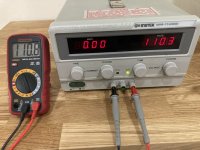
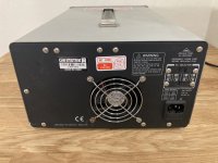
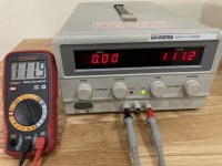
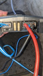
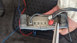
Actually I already have the battery and the knowledge to power the amp, I also have a carpenter dad so no worry for the box itself.
BUT
I have so many questions about audio. I have read so many things on internet and found so many ideas.


My first inspiration was the Russian YouTuber "Pasha Es" that build a pretty decent speaker with minimal price:
-(his video with the final result) УЛИЧНАЯ ОРАЛКА XPL VS SOUNDBOKS 2 - YouTube

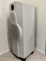
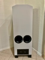
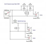
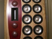
So my idea is to build a similar speaker with two 10'' sub/mid vertically and two tweeter between them (I like symetry), with one vent on each side like the soundboks 3. (But a bit more powerful than him. 50w --> 500w.)
I link a really basic draw of the front face so you don't have to look at the video:
k1KsPHn


To have a loud volume on a portable system I fast understood that I would need high sensitivity speakers to not drain the battery. So I looked at what he used and the problem is that he used speakers from xpl, an absolute unknown brand of speaker and I really doubt on the specs of these speakers.
The xpl xw10-403 would be able to 105db/w ?? (a 10 inch speaker)
Anyway even if they, in reality, only do like 95-97 db/w (what it seems to be in his video because he measured the db s.) They are cheap and cover the medium frequency.

I added two tweeters also from xpl because they cover the rest of the frequency
and they have high sensitivity (so the speakers will seems loud).

A 2x250w rms amp, a crossover for each output and a little preamp (with built-in bluetooth and an equalizer), from aliexpress. (I don't need stereo but by here I still kind of have it even if vertical speaker is not good xD.)


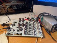
So here is my actual setup:
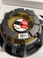
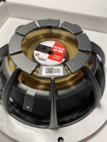
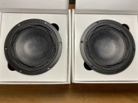
-2x 10'' drivers 1 MIDWOOFER XPL XW10-403 XW10 403 altoparlante diffusore medio basso 25,00 cm 250 mm 10" 200 watt rms 400 watt max 4 ohm 105 db auto nero, 1 pezzo : Amazon.it: Elettronica
-2x compression tweet XPL XTW4631 super tweeter driver 10 x 10 cm 200 watt rms 400 watt max sensibilita 110 db portiere sportelli auto spl bobina da 4,44 cm, 1 pezzo : Amazon.it: Elettronica
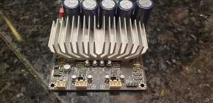
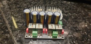
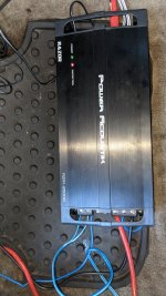
-2x 250w rms amp AIYIMA – amplificateur de puissance TPA3255 300Wx2 classe D, Audio numerique stereo, HiFi 2.0, haut parleur, cinema a la maison, bricolage | AliExpress
-2x crossovers AIYIMA – haut parleur 400W, reglage croise, 2 voies Audio, Tweeter, filtre de basse, diviseur de frequence pour haut parleur 2 16 Ohm, bricolage, 2 pieces | AliExpress
-pre amp with eq and bt https://fr.aliexpress.com/item/1005003331330014.html?spm=a2g0o.cart.0.0.4fac3c002k8sVL&mp=1
-and resistors to limit the tweeters if they sound too loud and the eq can't hold them.


So, I know these xpl speakers are sus but they're pretty cheap and loud and I didn't found others like this (with good wattage, good frequencies and sensitivity).


I won't post all of my questions but,

If you have any suggestions for others drivers or even the amp, by remembering I want cheap not good quality. It's just to play on partys for many friends.
Or if I said anything incorrect about audio (I just learned all the three last weeks)

Will this setup work or not at all ?

Will the tweeter be way too loud compared to the mid/bass ?

Should I go for one tweeter and how to wire it with two channel ?

Should I don't even try and wait for a real soundboks ? 🙁

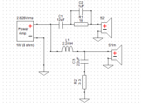
What really disturb me is how the Russian guy get this good result with 50w(rms) on 300w(rms) speakers with just capacitors to not blow his tweeter. ???


I will later ask myself about the box config, the vents,... now just the electronic parts.

btw, if there is someone form Switzerland that is also interested, contact me gladly.

Sorry for my English 🙂)


I hope you would be able to help me,
Have a really good day my future helpers. :hbeat::hbeat:

Two 20w studio monitors

Hi, Im making studio monitors and i dont know if 20w amp for each will be enought. My speakers are 4 inch. Also i have 150w sub, i know its over kill and that's why I'm afraid it won't be enough because 2x20w monitors with 150w is weird to me. When I read some posts they said that 20w for small room is enought. My room is abou 4x4 meters. Thanks for help.

Any info on TruTest TR117 Out-Put Transformer for Hi-Fi

Any info on this pair of Any info on TruTest TR117 Out-Put Transformer for Hi-Fi?

They look very similar to a pair of Sansui single ended HS-5 Output Transformer.

They also look very similar to some transformers I've seen installed in a Lafayette LA-240 (push pull EL84). The printouts on the power transformer of the Lafayette LA-240 were very similar to the ones of the power transformer of a Sansui Q-50.

Are the TruTest TR117 single ended as well?

IMG_1792.jpeg
IMG_1793.jpeg
IMG_1794.jpeg
IMG_1791.jpeg

For Sale DIY 3 Way 1" Seas, 6" PHL, 15" Ciare

Once you have heard a well designed, modern, speaker using a 15" woofer it's hard to go back. I am not a heavy bass person, I listen mostly to acoustic, vocals, some classic rock and electronic and it all just seems right through these speakers but the ability to reproduce deep bass is there if needed. Transparent, space around instruments, and detail. Never congested or edgy.


These speakers have a better than average sensitivity at about 90dB 1w/1m the impedance plot has a healthy 8 ohm load on average with an impedance minimum of 5 ohms at 39Hz. This shouldn't pose any problem for most amplifiers as the corresponding electrical phase is very smooth, staying within the +/-30 degrees range from 40Hz upwards and even in the bass it is within +35/-50 degrees. So your amplifier doesn't need to be very powerful although is it a lot of fun when it is! Even my 2 watt SE amp works well.


These 3-way speakers and components are based on Tony Gee’s “Mezzo Galactica”. Tony Gee is a respected speaker designer in the Netherlands. The cabinets are different than Tony's original and I was in contact with him about the design.

I used the same Seas Excel T29CF001-E0038 tweeter, the same PHL 1130 but, because of availability, I used Ciare’s NDH 15-4 instead of the NDH15-3 only because of availability. I did talked with Tony about this change. I used the same crossover design and the crossover is easily accessible in a sealed, separate compartment at the rear.


The cabinets are constructed using 1″ thick Baltic Birch plywood with extensive bracing. The front baffle is constructed of a double layer making it 2″ thick. I kept the interior volumes the same as the Mezzo Galactica design. I have used extensive interior cabinet bracing. This all adds up to some heavy cabinets. Each cabinet measures 46.25"h X 16.5"d X 18”w )


The interior of the bass cabinet is lined with 1/2" felt and mineral wool.


there are 2 rear ports that are tuned to 39hz.


The mid range cabinet is well braced, lined with 1/2” felt and filed with sheep's wool.


The crossover components are Jantzen Superior Z-Cap, Mundorf Supreme, Obligato, Jantzen and Mundorf inductors and Mundorf MOX resistors. It is a 3-way parallel crossover.

$1850.00

Attachments

  • tempImageXets84.gif
    tempImageXets84.gif
    1.5 MB · Views: 317
  • tempImagetptBjJ.gif
    tempImagetptBjJ.gif
    1.9 MB · Views: 250
  • A7BA69D3-4325-40FA-AF31-128996694CAF.jpeg
    A7BA69D3-4325-40FA-AF31-128996694CAF.jpeg
    395 KB · Views: 235
  • 16356895-A239-4969-9071-9524F051E5A4.jpeg
    16356895-A239-4969-9071-9524F051E5A4.jpeg
    343.7 KB · Views: 246
  • D200F856-26F9-4D16-AD27-5BB5D4D02675.png
    D200F856-26F9-4D16-AD27-5BB5D4D02675.png
    432 KB · Views: 203
  • 63737211-954A-447B-8E26-2CE29A7DC1D7.png
    63737211-954A-447B-8E26-2CE29A7DC1D7.png
    1.2 MB · Views: 224

For Sale FS: Tang Band W8-2145 Full-range 8" drivers

  • Pair of Tang Band 8" full-range speaker drivers.
  • In Like-New condition, these have an estimated 50 hours on them.
  • Used in a temporary speaker project, no longer needed.
  • Includes sturdy packaging
  • Original cost was $300+shipping for the pair, when purchased new from parts-express.com
  • asking $150

Available for local pickup in Boulder, CO ... or will work w/buyer to determine shipping.

https://www.parts-express.com/Tang-Band-W8-2145-8-Paper-Cone-Full-Range-Driver-8-Ohm-264-960

Attachments

  • PXL_20220308_013027775.jpg
    PXL_20220308_013027775.jpg
    374.7 KB · Views: 349
  • PXL_20220308_013041468.jpg
    PXL_20220308_013041468.jpg
    270.6 KB · Views: 218
  • PXL_20220308_013954409.jpg
    PXL_20220308_013954409.jpg
    456.2 KB · Views: 164
  • PXL_20220308_162537978 (1).jpg
    PXL_20220308_162537978 (1).jpg
    401.1 KB · Views: 185

For Sale Instek GPR-11H30D DC power Supply 0-110V_0-30A

Instek GPR-11H30D DC power supply. Maximum output 110V 3A Current selectable from 0 to 3A, output voltage selectable from 0V to 110V. In working order. comes with cord.

I have 2 of these and they can be connected in series for higher voltage and current rating. There are photos of both and price is $185.00 each. Buy 1 or both.
One of the units has some rust on the case as can be seen in the photo.

I have 1 manual but there are manuals for free online.

Attachments

  • AEF20F90-9B17-4B38-9CFA-7070C8F33059.jpeg
    AEF20F90-9B17-4B38-9CFA-7070C8F33059.jpeg
    471.6 KB · Views: 89
  • 70AF9872-8B2E-48AB-90F1-75F5AF04C9BA.jpeg
    70AF9872-8B2E-48AB-90F1-75F5AF04C9BA.jpeg
    415.7 KB · Views: 88
  • 18D84DEB-F27B-4473-833B-15285BCFB6CF.jpeg
    18D84DEB-F27B-4473-833B-15285BCFB6CF.jpeg
    376.4 KB · Views: 101
  • F0C6EB56-2622-4B5D-9192-D9FC64A023A2.jpeg
    F0C6EB56-2622-4B5D-9192-D9FC64A023A2.jpeg
    487.7 KB · Views: 89
  • E13BB183-9C22-43CA-9F1F-67AF48CD1D00.jpeg
    E13BB183-9C22-43CA-9F1F-67AF48CD1D00.jpeg
    424.8 KB · Views: 95
  • E6BF8699-057C-490F-AEB7-5452F505CB29.jpeg
    E6BF8699-057C-490F-AEB7-5452F505CB29.jpeg
    344.6 KB · Views: 92
  • 522AE380-84EC-4189-BC47-D90D281A3524.jpeg
    522AE380-84EC-4189-BC47-D90D281A3524.jpeg
    408.2 KB · Views: 90
  • 196810B9-CC42-44C2-A5E2-8923D3EF736B.jpeg
    196810B9-CC42-44C2-A5E2-8923D3EF736B.jpeg
    477.8 KB · Views: 103
  • BB8339F1-172A-459D-A3B1-6ECC84C2FBD2.jpeg
    BB8339F1-172A-459D-A3B1-6ECC84C2FBD2.jpeg
    386.7 KB · Views: 93
  • 44FC4430-19C4-4F5D-BEAF-4235C79DA3ED.jpeg
    44FC4430-19C4-4F5D-BEAF-4235C79DA3ED.jpeg
    377.4 KB · Views: 76
  • C62FADB9-BDB7-49C6-95CC-86B90A1499CA.jpeg
    C62FADB9-BDB7-49C6-95CC-86B90A1499CA.jpeg
    433.7 KB · Views: 77
  • D6360F7E-2867-4503-B68D-04D76C639055.jpeg
    D6360F7E-2867-4503-B68D-04D76C639055.jpeg
    359.7 KB · Views: 87

How to Use a DAC Evaluation Board?

Please forgive this extremely basic question, but I've been given a DAC evaluation board that I want to turn into a DAC I can use as line input to my speaker amplifier. I gather that I need to program it in order to to make sound. However, I've never used anything like this before and am not really sure how to go about it. I'd greatly appreciate any general advice, or if anyone happens to have set up DAC eval boards by AKM.

It's an Asahi Kasei 4413-SA (mfr. in 2012): coaxial and optical digital audio inputs, op-amp outputs, USB controller interface. It came with controller/measurement software that runs on Windows 2000. I had to dig out my 20-year old laptop in order to run the software and interface with the USB port on the board, which actually seems to work. But that's as far as I can get.

I've been trying to understand what it means to select or deselect the registers (things like "ACKS" that automatically detect input signal sample rates -- see attached pic). I'm guessing that I need to turn on the right ones by clicking their buttons and then "Writing" them to the processor via the software?

The manuals merely describe the features but provide no direction on how to set up a running DAC -- clearly it's meant for engineers or people who already know about these things.

I thought I'd turned on the ACKS and the four channel outputs. I've connected the CD player to the optical input, but no sound or even measurable voltage appears at the output BNC jacks.

Perhaps someone has set up an AKM eval board before? Any tips on getting started would be much appreciated.

Thanks!

Jeff

Attachments

  • eval-board.jpg
    eval-board.jpg
    542.9 KB · Views: 149
  • eval-software.jpg
    eval-software.jpg
    535.2 KB · Views: 145
  • laptop.jpg
    laptop.jpg
    500.7 KB · Views: 130

Waveguide/horn on cone tweeters

Anyone ever try it? It is quite common these days seeing dome tweets mounted behind a wave guide or horn but I wonder if anyone has ever tried it with cone tweeters. One of the big complaints with cones is directivity but the broad dispersion of the dome is negated to a degree when horn loaded or guided so perhaps the inexpensive cone might not be at a disadvantage in such conditions.

For Sale Bisesik transformer output hat for Ian Canada ES9038 dac hat

Hi

I have one of these boards surplus so may as well sell it on. I don't have any pictures to hand but it is the same as the board referenced in this post:

https://www.diyaudio.com/community/...ks-mods-and-hints.335881/page-54#post-5971440

and is the one with the round transformers in the photo there. Mine looks the same as that and is unmolested.

It cost £140 two years ago. I'm after £70 posted in UK.

NOW SOLD

DCM TF350 Refurbish

My quick refurbishing of our DCM TF350 Speakers. My goal was to save the originals as much as possible.
I only replaced the electrolytic caps since they were over 25 years old. The surrounds had died more
than five years ago. I forgot how laid back these speakers sound; It is a real pleasure to listen to them again.

New foam surrounds and electrolytic 47µF caps. Total cost about $35 [$25 surrounds, $10 caps]
Parts Suppliers: Simply Speakers & Parts Express

I did have to modify the inside lower area of the gasket. When placed in the basket with the new foam
surround it pushed on the foam and distorted its shape. A little dremel work to shave away a chamfer
on that inner edge to prevent the gasket from interfering with the movement of the foam surround.

The dark area on the cone is from the application of too much alcohol when softening the original
adhesive. It pulled the black adhesive down then promptly dried. It is behind the grill cloth so
there is no harm visually.

Foam Surround glued to paper cone
An externally hosted image should be here but it was not working when we last tested it.


Grill cloth rolled down exposing crossover
An externally hosted image should be here but it was not working when we last tested it.


Crossover rear
(Notice the hand drawn traces and sloppy soldering by DCM)
An externally hosted image should be here but it was not working when we last tested it.


Crossover top
(Notice the copper tube glued in the center of the inductor by DCM)
(Notice the new 47µF cap installed)
(Black/Red Woofer, Green/White Tweeter)
An externally hosted image should be here but it was not working when we last tested it.


Remounted driver
An externally hosted image should be here but it was not working when we last tested it.


Finished refurbish with original grill cloth
An externally hosted image should be here but it was not working when we last tested it.


Schematic for DCM TF350
An externally hosted image should be here but it was not working when we last tested it.

Subwoofer Amp - Fried resistor?

Hi all,

After a little help again.

Just purchased a second hand sub which I set about cleaning and checking visually just to make sure everything is ok before adding to my system. (Note I did hear the sub playing before purchasing and all sounded good)

I noticed on the amp board there is a resistor that looks a bit suspect. Could someone please confirm if this resistor is ok or if it would need changing before using?

There does seem to be alot of this the tan coloured goo over the board which in some areas, such as on this resistor, has turned black and charred. Excuse my ignorance as I'm not sure what the goo is actually for?

Many thanks,

IMG_20220626_225218__01.jpg
IMG_20220626_225321__01.jpg

Help pick the best transistor.

Im working on a DIY Amp Module.
The creator has given me this list of options.
Im sure for some of the wizards here with decades of exp they could look at it and go this or that.
But to somebody like me just starting out its taken a few days just to download all the data sheets and read them.
After that I dont even know what I need to be looking for in the datasheet to compare which is better.

Any help or guidance in helping me pic the right one would be appreciated.
If you cant cherry pic an option from the list then what parameters are critical in the data sheet. For me to look for.
Also if you have used any and have found it to work well that would be ok also.

@ all ASUS Xonar D2X owners

Hey people,

I'm using a Xonar D2X as one & only signal source for my speakers. It's all active and the channels are rerouted via EQ Apo, so I have 3 channels left, 3 channels right + Subwoofer. I've bought the Soundcard years ago at an online-auction for, at that time, just 30€ and I'm totally satisfied with the sound.
But, as the card was always in use, and sometimes I tried a mod here & there, I assume, it could be possible the card lost the one or other surface mounted part on the backside. As I've got nothing to compare, I'd like to ask you for some good pictures of the backside, so that I can compare, if there is something missing, or not. The card is still working, but I just want to be sure that everything is still at it's place.

best regards
J.

FS: Parts for Slagle autoformer pre with Goldpoint remote kit

A while ago, I bought parts for an all out preamp build using Dave Slagle's autoformers. Specifically, the 28 step bare autoformers that need to be wired up. Description as follows from Dave's site...

28 Step Autoformer Volume Control (AVC)
The Demand for more positions and finer attenuation steps has brought about a second product. This device has 28 steps and provides attenuation from 0dB to -52dB in 2dB steps.This uses a similar approach as the $200 kit but has a 28 pin bobbin in place of the 14 pin. When wiring this device to a switch with fewer than 28 taps you simply assess your gain structure and choose the appropriate steps.
Price: $500 a pair


I also bought a remote control solution from Intact Audio along with a Goldpoint stereo blank as well as a selector switch. The GP kit also has the stand-offs for balanced if you ever go 4 deck. Descriptions of these are as follows from the Intact Audio and Goldpoint sites:

The Intact Audio Goldpoint Remote Control Kit Specs:
  • Required voltage = 9Vdc to 12Vdc
  • Required Current = approx 1 Amp when turning.
  • Very low 4Ma standby current (when the motor is not turning)
  • Step Size is 15 degrees per step standard
Goldpoint Stepped Attenuator Remote kit Price.....................$160.00

$123.00 USD
Goldpoint Stereo V24C Custom Attenuator (blank), P/N V24C-2

$75.00 USD
Goldpoint Selector Switch, 2 Pole, 3 Position, 1 Deck, P/N 2P-3T-1D


So now I'm selling because I don't plan on using a dedicated preamp anymore. $858 in parts, selling for $700 shipped in the CONUS.

Also willing to sell stuff separately.

Thanks for looking!

RF Punch 40 DSM

I've got a Punch 40 DSM I am starting on. It has leaking electrolytic capacitors on the main board as well as the input/pre-amp board (2nd image). I will replace all of the smd electrolytic caps. I guess I also need to remove both LM833s to clean the electrolyte residue from under them. Is that correct?

But first I have a question about the P.S. driver board. I am trying to find out if I am missing parts or if some 40 dsm's did not have a LM393.

I have found one pic from a thread by @Dr Zeus https://www.diyaudio.com/community/threads/rockford-punch-40-dsm.371046/ that is missing the exact same parts I am missing other than he also was missing the LM339D which I have on mine.

All other photos I have found of the PS driver board show it fully populated. What gives?

Currently the gate drive on the PS FETs looks good and I have +/- 21 Vdc for the rails and +/- 12 Vdc for the secondary supply.

Attachments

  • Punch 40 DSM Driver Board 1.jpg
    Punch 40 DSM Driver Board 1.jpg
    313 KB · Views: 145
  • Punch 40 DSM Input Board.jpg
    Punch 40 DSM Input Board.jpg
    199.2 KB · Views: 162

REL T5X Clone

Hello,
Looking at building a REL T5X clone due to the positive reviews I've been reading. Can you recommend a plate amp and bass driver combo?
Requirements are:
1) Sealed box
2) 8" woofer
3) High level input
4) Not sure about the amp's power but I don't need much since my listening space is quite small (10ft X 12ft open back)
5) Plans with a proven design
I've built a few speakers, so the wood work is not a problem. I just need a woofer amp combo to come close to the abovementioned subwoofer.
Thanks for your imput.

A Fistful of Solder

This thread is dedicated to the discussion of simple amps. The only requirement is that it have about 12 or fewer components. These will usually all fit inside your fist, hence the thread title. For those using SMT parts, you could fit 2000 parts in your fist so that doesn't count! 🙂

I have built several myself, and I always find that they sound very good, honest, and oftentimes, very lifelike with a super quiet background.

I think my Pocket Class A amp was the first one.

616921d1495124663-xrk971-pocket-class-headamp-gb-pocket-class-schematic-v8-voltages.png


Hand etched PCB using Sharpie marker as acid resist:
591358d1484063759-bf862-based-se-class-headamp-without-heat-pocket-class-bf862-zvn5306-ha-v1-new-oscons.jpg


I think Adason made Juma's LU1014D headphone amp, that certainly qualifies.

have fun!
  • Like
Reactions: JMFahey

Recommendation of speakers for my living room - line arrays or?

My living room arrangement is really speaker unfriendly. Its dimensions are 578 x 391 x 250 cm (L x W x H) and there are basically only two places for speakers on the front wall.

1. in the ceiling corners - max box height ca 33 cm - or in the middle for some kind of single box stereo arrangement.
2. into the corners - line arrays 170 cm long starting at the ceiling, limited in width to about 15 cm or slightly more if built with angled baffle to avoid the heating pipes. Or small satellites (like Bose🙂 ) Or long thin DML panels masked as decorations...

There are some options for hiding subwoofers if necessary (TV table, lower right corner if made in a special shape to fit around the pipes somehow.

The listening position is ca 3 m from the front wall. There is an opening to another room on the left (ca 200 x 220 cm) and a window on the right of the corner.

The main use would be stereo music but they would be also used as TV speakers.

A commercial option would be a Bose sub/sat system with single/dual cubes slightly above ear height or a DSP soundbar above the TV. I heard the Bose dual cube sub/sat system as Jukebox speakers in a bar that is at least three times the size of my living room and it was quite adequate and the sound was not too bad when sitting at the correct position.

This should not be the best of the best, but the best compromise for my living room. I have two great systems around the house, this would be for the family to enjoy loud and clear sound as well. Exotic suggestions are very welcome🙂 and a CNC for cutting any weird shapes will be at my disposal. Using ceiling reflections, omnidirectional, Sonab style mounting, anything. WAF factor is something to consider, but unorthodox solutions may look attractive and decorative.

Attachments

  • FFB95362-9468-4E8D-8BC0-04975D604066.jpeg
    FFB95362-9468-4E8D-8BC0-04975D604066.jpeg
    209.5 KB · Views: 379
  • 0F4F7BE6-DF27-4DEF-A8CD-DAA9CCD0CB77.jpeg
    0F4F7BE6-DF27-4DEF-A8CD-DAA9CCD0CB77.jpeg
    84.5 KB · Views: 399
  • B5EAEC40-6033-4251-AE34-B864820BFA4A.jpeg
    B5EAEC40-6033-4251-AE34-B864820BFA4A.jpeg
    126.7 KB · Views: 365

Balanced Toroid Group Buy

Folks:

Toroid Corp has offered to extend discounted pricing to everyone in who participates in a balanced toroid group buy that I am willing to sponsor. You can get any model sold by Toroid Corp (i.e., 250W, 500W, 1000W, 1500W or 2000W; see https://toroid.com/balanced-transformers/ for information about the various models) and pricing will be based on the aggregate number of units sold through the group buy regardless of the model(s) selected. Pricing drops considerably fairly quickly, so this should be a great opportunity for every participant. When the time comes, you will pay Toroid Corp directly and they will ship directly to you. You'll be responsible for your toroid's shipping cost; Toroid Corp has facilities in the US (Salisbury, MD), Europe (Brno, Czech Republic) and Brazil (Parana), so factor that in. I am considering building two balanced power conditioners using Toroid Corporation model BT1000X balanced toroids (https://toroid.com/sku/BT1000X/), but you are free to get whatever size you want.

If interested, please add yourself to the list below. The deadline for participating is Saturday, June 18.

Name Model Quantity

SRMcGee BT1000X 2

Kontakt KT-7 ~ Grounding Conundrum!

Hello! I'm a newbie to this forum so I apologise if this isn't the right place to put this thread, and also for my lack of experience 😅

I'm no electrical engineer, just someone in their late teens without too much experience in vintage audio so any guidance / help would be appreciated on this 🙂

I've been super intrigued by valve amps for a little while now but I've been a bit picky and quite a cheapskate up to this point too 😅 I finally decided to dive in headfirst last week and picked up a Kontakt KT-7 Single Ended integrated from around 1967, Japanese made and sold in the Netherlands, in working condition but in need of a good service. There are a couple of variants out there but mine is the original 5 valve model (2x EL84, 2x 12AX7 and an EZ80 rectifier) without the additional MM phono stage and luckily I have access to a full schematic which I found online (Also attached below).

For it's age the amplifier is still surprisingly working alright, but the tone controls feel very non-linear with only a very small sweet spot and otherwise the music ends up sounding very shrill or very dull. It is manageable and I can still get the amp to sound just right but my biggest gripe at the moment is some audible background interference / hiss heard when there's nothing playing. It isn't 50hz / 100 hz humming and it does change with the volume control, if that helps 😅

All I've done for now is given the potentiometers some Deoxit fader lube and checked for any cold / corroded solder joints to no result. This amp still has all of it's original capacitors aside from two which seem newer than the rest (The 2 red WIMAs between the pre / power valves) and I intend on replacing the lot of them, one section at a time before I do any proper heavy listening with the amp. That's all fine and well, I've ordered some replacement parts from Mouser and they'll be in the UK within a few days but until then I find myself staring at the schematics and looking into the amp confronted with a new problem - the way the grounding is wired up. I don't have many complaints about the wiring of it as it does seem to be done as per the schematic, but it looks like one of the speaker terminals is being used as a star ground point (yikes!) and a lot of the design relies on the tag boards and their respective centre pins being soldered directly to the chasis for mounting meanwhile doubling up as a ground path, with the original main ground point (I believe) being at the 265v HT centre tap. At one point it looks like a previous owner has replaced whatever the original power lead was with a 3-core mains cable and has screwed down / soldered the earthing conductor to the chasis as you'd expect, but the original schematics don't have any reference to a CPC / earthing terminal and it doesn't look like this amp was designed with that kind of earthing in mind whatsoever. I'm not sure what Japanese / Dutch electrical standards at the time were like, but it makes me think that the "new" (Well, newer) earthing / grounding arrangements could be responsible for causing said interference on the amp, especially since it can change depending on what other appliances are plugged in / being used around the house.

I've looked into adding a grounding bus that would be connected back to the centre tap and it would be a possible modification for this amplifier without too much extra work so that the dependance on the chasis for ground could be addressed. I'm not ruling out the possibility that my interference issue could be caused by something else / an issue that gets solved during the recap, but at the very least it's an improvement I have in mind. I'm pretty happy with how I'd go about doing most of it, but I'm a bit stumped when it comes to the secondary side of the OPTs as some people claim the common (black / - speaker wires) wires must be grounded too for safety reasons. That's all fine by me and I understand the reasons for why this is done, but I've also heard claims that with a single ended setup like in my case, it's an optional choice to make and that it can affect the sound, etc etc etc.

So all of my rambles aside, here's my newbie question:

Whether I'd like to do it or not, I'm just wondering should I connect the common speaker terminals directly to the chasis earth point or to the power transformer's centre tapped ground? Assuming that they were no longer connected to one another by the chasis. And if I were to connect my hypothetical grounding bus in order of: centre tap > PSU / coupling caps > EL84 > 12AX7 > RCA terminals, where should the OPT common wire be connected between in that case? If not on the grounding bus, then just directly to the chasis earth wire? Please let me know your thoughts! 🙂

Photos of the amp attached below:
KT7 valves opts.jpg


KT7 2.jpg
KT7 3.jpg


20220628_153327.jpg


The OPT secondary wires should be as follows:

16 Ohm - White
8 Ohm - Yellow
Common - Black
And supposedly the blue severed ones are unused connections for a 4 Ohm tap that may have been intended for other amp models

Sorry for the poor-ish quality of the photos, but hopefully they're good enough to give a general idea, at least! Also take note of the black wires which all tend to go towards the grounded centre pins of the tag boards (Also yes, I do intend to touch the mains wire points up too once I start properly working on this thing. That cable tie is naaaasty)

Thanks for reading! 🙂

Attachments

  • Kontakt KT7 origineel (Japan).jpg
    Kontakt KT7 origineel (Japan).jpg
    549.3 KB · Views: 278

MN Speaker Builders - Can I have a listen?

I am still debating what the heck to do for my next speaker build and one big challenge is that I really haven't heard a lot of different speakers. If you happen to be in the twin cities area and willing to let me take a listen to your creation(s) I would love to hear what you have been building. I'm looking at bookshelves, monkey coffins, econowaves, floorstanders... interested in hearing it all.

I'm not normal, of course, but I can pass for it sometimes and will bring beverages of your choice if you let me know what you like. Please feel free to reach out by PM and I hope I can find time to connect with some of you.

Thanks much, Mike

For Sale 5V 3.5A external linear PSU, ultra-low noise

New in box: 220VAC to 5VDC external linear power supply, ultra-low noise. Voltage is fine-tunable with a screw on the back side. Maximum current is 3.5A. Asking price: € 50, shipping from The Netherlands.

Outputs:
  • 1x 5,5 x 2,1 mm jack plug
  • 2x USB-A (note: 5V only)

Of Chinese make but with high quality components:
  • 4x high speed diodes
  • Philips filter capacitors primary side
  • Panasonic FC and Siemens filter capacitors secondary side
  • includes EMI filter

Dimensions (b x l x h): 102 x 150 x 60 mm
Weight: 1,1 kg

Also available in 12V.

DD M5 got rained on

Have a DD m5 (older version) blown 1 out of 4 output sections, only about a month use on it, his hatch didn't fully close and rain and strong wind in the correct direction to wreak havoc rained in on the preamp side. Needless to say it didn't play, it didn't go in protect he said. This amp has the speaker terminals and power terminals on the same side and they were dry but the amp did blow 1 "output amplifier", all 6 fets were shorted in one way or another, only one exploded violently. I'm not seeing any evidence of water intrusion but it obviously had to have something unless rain getting on the RCAs could be the culprit? RCAs are the panel mounted style, has no pass thru "out" RCAs but does have master/slave independent terminals that did not have anything plugged into. The "In" obviously had connections so i don't foresee that being the cause. I'm looking for ideas on what to check or what would have caused just the one section to go but the 3 others are just fine and fets test the same as new on my tester (for whatever that's worth) I'm currently limited on supplies and am unable to install fets back in to test (to removed them,I cut the legs) can I check the pads to find out if anything else is potentially failed with the scope until i get my soldering gun in? Been a while since I've messed with amplifiers so I do not recall and would rather not find out on this 5k 😂

Thank you in advanced for any advice.

Transformer impedance and local feedback.

I am thinking primarily in terms of SET but I suspect the issues involved are kind of universal. Here is my thinking; please critique.

Load impedance on the output tube affects power output and distortion. Starting at some "optimum" load if one reduces the load impedance the maximum power delivery goes up but so does distortion. The question is simple but I suspect the answer is less so. Let us say that 5K is the normal load which gives good all around performance. If you were to reduce the load to say 4K but add local feedback such as plate to cathode could you get a best of both worlds situation with higher max output power but similar or even improved distortion due to the FB? Of course I am assuming sufficient gain.

On the one hand the plate curves are not changed (I don't think) but the local FB reduces effective driving impedance and reduces distortion in a brute force way.

So is this a reasonable way to make use of lower than optimal load trannies? Dumb idea?

Dynaco ST-150 PC-43 question

Hi, Gang,

I'm making a new PC-43 with Eagle and do not have an original board. I'm incorporating all of the Boak-Jung mods from AA plus a few other tweaks of my own.
I know that Q6 has to thermally track Q10 & Q11 by mounting on the same heat sink and have laid out the board for that.
Looking at the copy of the board fab in the assembly manual, Q8 and Q9 are adjacent.
Can anyone kindly provide a picture of a populated PC-43 or tell me if Q8 & Q9 should also share their own heatsink?
Also, does anyone know where to get the little TO-92 clamps Dynaco uses to attach Q6 (and other TO-92s) to a heatsink? These are used on the ST-150 and all versions of the ST-4xx, but I'm not finding anything like that in Digi-Key or Mouser.

Thank you!
Cheers,
Frank

Mackie SWA1801Z amplifier board

Hi everyone ! I have a problem with the amplifier of a Mackie SWA1801Z subwoofer! it does not have damaged transistors or mosfets, but the delivered power does not correspond to the characteristics and the output signal has a crossover distortion at low volume. Another strange thing is that if I try to send more input signal the output signal does not increase and the output value does not exceed about 30v RMS. Is it possible to have the wiring diagram? Thank you and good job to everybody

Attachments

  • 20220628_150605.jpg
    20220628_150605.jpg
    548 KB · Views: 266
  • 20220628_150559.jpg
    20220628_150559.jpg
    556.6 KB · Views: 262
  • 20220628_150541.jpg
    20220628_150541.jpg
    506.4 KB · Views: 207
  • 20220628_150822.jpg
    20220628_150822.jpg
    599.6 KB · Views: 206

  • Locked
The battle of the DACs, comparison of sound quality between some DACs

Hi guys!
given the cancellation of the last open threat without any explanation. I state that the material I was lucky enough to be able to bring is available on this site.
I also state that I have no interest in speaking well or someone might say promoting the following products.
I bought a lot of material from ian, ryanj, bisesik and of course also from andrea mori so I talk about my experience as most people do in every forum.
We did a listening day to compare various dacs, all with the same source,
usb-i2s andrea's fifo notebook.
we were 5 people one hifi enthusiast for years and a great listener of live music, two have come from over 40 years of DIY in hifi, I from 5, the last one also for a long time in DIY.
we all agreed on what I wrote below.

7) SABER the first of the participants - ES9038PRO sigma-delta driven in true sync. The worst we heard that day, flattened, lack of dynamics, grainy and veiled midrange, tight and shallow soundstage, lack of focus

6) Twisted Pear Buffalo III SE - ES9038PRO sigma-delta still true sync. slightly better, same defects, but far from what we were looking for

5) TWSDAC-AD5791 - AD5791 20-bit R2R dual mono sign magnitude. slightly better, but perhaps less dynamic than the saber.

4) DDDAC1794 - Doede Duma PCM1794A 24 bit sigma-delta dual mono sync NOS. Here the situation improves, nice musical to listen to but a too relaxed sound, lack of energy, the midrange remains a bit flattened, quite detailed but still narrow and shallow soundstage

3) TWSDAC-1862 - AD1862 20 bit multibit R2R dual mono sign magnitude NOS. At this point the qualitative leap starts to be significant, regular midrange, very detailed but never harsh high frequencies, deep and articulate solid bass, sufficient dynamics, bigger and more focused soundstage

2) TWSDAC-1541 - TDA1541A 16 bit mutibit R2R dual mono sign magnitude NOS. Further improvement compared to the previous one, one of the best medium ranges ever listened to, less wide but clear and soft high frequency, even more solid and extended bass, excellent dynamics, wider and deeper soundstage. the sonic planes begin to come into focus. definitely the best dac chip ever made.

1) TWSDAC-LT-DAC Lite. 24 bit multibit R2R NOS with digital calibration. The best we've heard, impressive dynamics, but never broken down, even smoother midrange, open, detailed, crisp and never harsh high frequency, deeper and more articulate bass, much wider and deeper soundstage than all DACs, no confusion between the floors and between the tools. here the result is truly incredible on every aspect. seeing is believing.


WhatsApp Image 2022-06-01 at 13.54.11.jpeg


WhatsApp Image 2022-06-01 at 13.54.10 (4).jpeg
WhatsApp Image 2022-06-01 at 13.54.10 (3).jpeg


WhatsApp Image 2022-06-01 at 13.54.09.jpeg
WhatsApp Image 2022-06-01 at 13.54.09 (2).jpeg


WhatsApp Image 2022-06-01 at 13.54.09 (1).jpeg
WhatsApp Image 2022-06-01 at 13.54.07.jpeg

Looking for source for 4.4mm plugs and jacks

I've been looking high and low for quality gold planted 4.4mm jacks and plugs, but i'm not having a lot of luck. I can find a few cheap as hell jacks with those damn pin terminals, but I'd like ones that have proper soldering tabs. I'm looking for both cable to cable male and female gold plated 4.4mm connectors as well as right angle through hole / panel mount female gold plated connectors. preferably a place where I can order 1 to start out with, and if I like it by the hundreds afterwards.

I've tried the usual digikey, mouser, arrow, octopart etc. looks like the only sellers are aliexpress / alibaba and resellers

Thanks.

Alpine PDX M6 - 43VDC Output

There is limited information on repairing only the Alpine PDX (gen2), so I figured make a thread only for the PDX. Long story short - I found out after getting my JL 13TW5V2 repaired by JL for $230 😡 that the amp was the reason why the sub failed (melted cone + snapped voice coil), not my occasional listening preference. If you hear a loud turn-on thump while using a PDX, turn your head-unit off immediately to preserve your speakers. The protection circuitry is only to prevent an over-current, over-voltage, and ultimately thermal runaway condition for safety and liability purposes - its not trying to protect your speakers.

My PDX M6 outputs a constant 43 VDC voltage, regardless of whether any signal input is provided to the RCA input. After reading through various other experiences with this amp, and the MRV (or MVR) which uses the same class D switching, I am planning or have already:

1. Done - Exercised the theory of having a loose subsonic switch 'in the middle' of the three state options. With only power/remote connected, the speaker output was still constantly 43VDC, while switching between 30 Hz to 15 Hz to off did nothing. It was set at 15 Hz.

2. Done - bench power the unit at 14.4VDC, then probe the audio driver ICs to check whether they are working properly. I've read through issues which other's have experienced on both amps, and it sounds like the original PWM audio driver ICs can go bad rather easily. I have the M6 Service Manual with all the test point voltages - so I may as well test. Update..PWM driver ICs were ok, all 8 FETs were ok, spot checked some other components on the bottom board and they were ok. I didn’t check anything on the top because that ribbon cable is so short...I’m sure a tech would have a longer ribbon cable for proper testing. Seems like the problem worked itself out once I fed it 14.4VDC.

3. To-Do - Replacing both 98-1036TRPbF PWM audio driver ICs with an IRS20965S, then test to see whether the 43VDC goes away. If it doesn't go away, I may end up just sending it in for repair.

4. Optional - Replacing all 4 Power Supply FETs and all 4 output FETs. If the amp resumes operation after replacing the IC's, I may still go ahead and replace the FETs to refresh the amplifier - hopefully clock in a higher true power rating. The FETS all look good (they aren't brown or cracked), don't have any shorting, but 'fail' a handful of FET tests - caveat is that they are still in-circuit.

If anyone else has any other thoughts or has experienced the same failure, please chime in to provide some assistance. Thank you in advance!

Micromega Tempo 1 schematics, draft

Hello, please see attached part of Micromega Tempo 1 power amplifier schematics.

I tried to reverse engineer it and draw circuit diagram of the power end.
It is DRAFT so it includes mistakes, wrong part numbers etc but maybe this encourage someone to finish it.

I made it using Kicad so if someone wants a Kicad file then let me know. The attachment is pdf.


Enjoy

Attachments

New OB project with Faital Pro 8" coax and 18"

I sold my house and won't probably have a dedicated hifi/TV room ever again. So I will build new speakers for the living room.

My latest effort was a two way OB (planar+15") plus IB subwoofer. See picture.

Planar combo was very clean sounding, but it was also a bit too polite at low volume.

I recently bought a pair of Faitalpro 8hx150 at a great price.
https://faitalpro.com/en/products/Coaxial_Loudspeakers/product_details/index.php?id=351030100
I plan a 3 way with OB coax on top supported by an H frame 18fh500 at bottom. DSP xo at 1700 and 160hz.

I already made a quick test with naked coax supported by a 15" and it was very promising. There was no ringing or harshness when the Tweeter was EQed and gain adjusted. Compared to planar combo, this setup has more dynamics, realism and body. It was a short test period, but to my surprise, I did not miss the dipole upper mid and treble. We will see how it goes once the build is complete.

Comments welcome on design and driver selection.
IMG_20220330_182155.jpg

Volt BM228.8 Tweeter pairing (Two-Way)

Hey everybody,

Over the last few weeks i've finaly been taking my first steps into making my own loudspeakers.
First project has been a crazy setup for a 16 channel sound installation, where i got to design all loudspeakers.
Notably where these coaxial SB Acoustics 5" and 6" variants, but maybe more on this another time.

Long story short: Great experience to built something, now let's find out what we can achieve with a little more budget.
The plan is to build a set of small studio monitors using the Volt BM228.8 woofers and i'm looking for a good pair of tweeters to go with them.
All will be powered and filtered by a Hypex FA123 (using two channels bridged to drive the woofer).

On the short list so far are:
Scan-Speak D2905-990000 (Have been used in this configuration before, as i found out)
blieSMa T34A-4

Both tweeter should be able to go low enough to cross them around 1.6; matching the Volt.
So here's the main question: Does anybody know any other tweeters to look at?
Any general advice about my plans are also quite welcome as well!

Thanks in advance!

_DSF3983Small.jpg

SOS help! Amp is in protection mode

Good morning everyone,
I purchased this power acoustik razor RZR1-2500D amp from Walmart, I had a friend of mine set up the amp . I come to find out that the amp isn't giving no sound and the amp is on protection mode. Can someone please guide me the right way.

Attachments

  • PXL_20220625_141333915.jpg
    PXL_20220625_141333915.jpg
    525 KB · Views: 1,334
  • PXL_20220625_141431366.jpg
    PXL_20220625_141431366.jpg
    354.8 KB · Views: 500
  • PXL_20220625_141506676.jpg
    PXL_20220625_141506676.jpg
    375.4 KB · Views: 885

Wiring for dodecahedron loudspeakers

Hi all! Hope you are well and keeping safe in these strange times!

I'm currently building a dodecahedron loudspeaker for acoustic measurement purposes, but I'm looking for some advice on wiring the 12 drivers.

I think that professional manufacturers use a combination of series and parallel wiring to prevent the resitance from getting too high / low, but I'm looking for any advice from this forum as to how many parallels and how many series connections 🙂

The speakers I'm using are 4 ohm, (12 of them, obviously 🙂 ) and the amplifier I'm planning to use has an output of 2x400w @ 4 ohm.

My main concern is safety, and not setting the house on fire!

Any advice is greatly appreciated and will be repaid with beers if you are ever near Wigan UK 😀

Altec 605B crossover

Hi all,

I have been using this crossover on my 605Bs for a while, favouring it over the Markwart version. My question however is : what's the correct/nicest way to pad the horn 1-2db? 2 resistors in an LPad configuration after the all-pass filter? a series resistor before or after? anything else? I have calculated several lpad values and tried them, but usually feel it brings some messiness in the crossover region.

Attachments

  • xsim_605B_sch.png
    xsim_605B_sch.png
    3.7 KB · Views: 123

Hi-Fi amplifier using STK4042Xi

Hello,

I have made this amplifier (Fig. 1) out of pure curiosity – I wanted to test a pair of brand new STK4042Xi ICs sold by Reichelt GmbH from Germany. My tests indicate that rumors about fake STK ICs are wrong, at least if you purchase them from reputable supplier. I don’t know who is producer and where the ICs were produced, but I can conclude, that the measurement data are consistent with the original SANYO technical documentation.

The product came as a positive surprise: both subjective impressions and measurement results are quite fine.

From the results below (Fig. 2) one can conclude, that based of these ICs it is possible to build a fine 80W Hi-Fi amplifier.

Measurements indicate that THD is consistently much lower than 0,1% and also that there is a very low noise floor. Measurement results of harmonic distortion present in a 1KHz and 10 KHz signal at 30W output are presented in Fig. 3 and 4, respectively.

To make this amplifier I have used:

2X STK4042Xi (Note that the suffix Xi indicates High Fidelity product)​
1X PCB from Aliexpress (Tianle HiFi STK 4040-4050)​
1X 400VA/230V toroidal transformer with double 30V secondaries​
1X Heat sink (Fischer Electronics SK56 100, 0.4K/W)​
List of components is in the attached .7z file​

For testing I have used:

Oscilloscope Rigol DS1074Z-S Plus​
Arta software​
Sound card: Xonar U7 Mk II​

Figures

Fig 1. A photo of the amplifier on the test bench
STK4042Xi-Amplifier-01-Resized.png

Fif. 2. Measurement results THD (+N) values at different power outputs, at 1KHz

Measurements-01.JPG

Fig. 3. Measurement of the harmonic distortion present in a 1KHz signal at 30W output
STK-01-1KHz-Resized.png


Fig. 4. Measurement of the harmonic distortion present in a 10 KHz signal at 30W output
10 KHz-Resized.png

Attachments

Projects by fanatics, for fanatics
Get answers and advice for everyone wanting to learn the art of audio.
Join the Community
507,683
Members
7,884,100
Messages

Filter

Forum Statistics

Threads
406,027
Messages
7,884,100
Members
507,683
Latest member
NenoCaldas