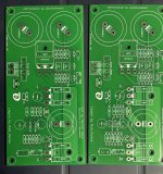
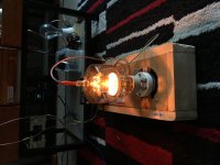
Abbas Audio- wow

have you guys seen this company? looks like audionote philosophy taken to the extremes- tubes and vintage components, overkill.

no doubt it sounds something special. 'different', at least.

no matter how sensible the design is i see a lot of passion in that and i admire that.

what do you guys think?

germanium i/v?

????? ?????????? ?? ???? ??????? ?????? abbasaudio.com

?????????? ??????? ??? ?????-?????????? ??????????????? Abbas Audio - Abbas audio

Cyrus Quattro(dAD3) CD player skip

I have Cyrus Quattro very similar to dAD3. It did not recognise any CDs but after cleaning the laser it does now. However it skips the track here and there for a part of a second. It does not mute and doesn't make the usual click sound - just small part of the sound gets missing. Is this rather laser(digital) problem or mechanical? My Cyrus dAD1 I am working on still has serious dried grease problem. So maybe this Quattro that shares the same transporter model has it too.

Current source low voltage amp bridged with big voltage amp

I've been toying around for a while with current source amps and I found some interesting threads when lurking around: https://www.diyaudio.com/community/threads/better-amp-configuration.108208/post-1298721

My idea is to combine that concept with a current source amplifier as the flea amp instead of a voltage amp. Basically use this topology (https://www.current-drive.info/9, https://www.current-drive.info/projects/45) but instead of having a modest -1.15x gain on the bridging amp to have say -10x gain.

If I've understood correctly I should be able to basically just take any off the shelf half bridge voltage amp with sufficient closed loop gain (I have a few 20x (26 dB) gain Class D amps lying around) and just hook up the following topology and it will just work?

Current source boosted flea amp.png


I don't want to have to modify the bridge amplifier. I've done experiments where I've tried to wrap feedback loops around closed loop class D voltage amps but they have all been pretty unstable. If I as much breathe on them they starts to oscillate like crazy.

This topology would in theory be much more simple. No complex current feedback and I could even build the flea amp without feedback making it even more simple.

But will it work? The original amp is DC coupled, this on is capacitively coupled but should still work right? And if it should work, do the resistors seem appropriate? I just copied them from https://www.current-drive.info/projects/45 but adjusted the R1/R2 ratio to get a ratio of 10x gain instead of 1.15x.

Can any of the DIY First Watt amps be 'derated'?

I'm very pleased with the sound of my ACA 1.6/8 (in stereo mode) even into my 85dB, nominal 6 ohm, speakers, but would like to build something a little bigger (but not another ACA), say 15 watts per channel, with more into a 4 ohm load. Hopefully also saving on enclosure size (important in my typically small UK room). Do any of the First Watt designs lend themselves to such a 'derating' without losing their sonic signature, and if so, how? Many thanks.

IG-18 THD Mod Question

Hello,

I picked up an IG-18 audio signal generator and am applying the THD mod available from HeathKit. I cannot figure out where to connect the VCC wire. The instructions are here: http://www.d8apro.com/IGA-18-1.pdf The VCC arrow seems to just be pointing to a blank spot on the wave generator board. My guess is to connect it to "A" in the upper right corner but would appreciate if someone could confirm or correct. Thank you.

For Sale Neurochrome 21st Century Maida Regulator Rev 2.12

SOLD

Asking $100 including continental USA shipping.


This is a kit, ready to build, of the previous generation of the 21st Century Maida Regulator for Tube amplifier B+ supplies.

The board is as bought with the surface mount components already factory soldered.

I am including all the other board components necessary to build it up for 315VDC. It uses some nice DC Link power capacitors.

It only takes two resistor changes for other voltages up 500v, wattage max of 230 Watts.

I am also including a heatsink that should take care of sinking most typical voltage/current applications.

IMG_0688.JPGIMG_0689.JPGIMG_0690.JPGIMG_0691.JPG

F/S First watt B1 preamp

Brought this about 6 weeks ago i was hoping to swap out the volume pots and try some AVC volume controls as a experiment but they are to big to fit in the case work (would foul the pcb).This is the better R2 version direct coupled (no coupling caps) is in very good condition only a few very minor marks.Sounds good for the price point but i think it would be even better with decent volume pots (the ones in there dont look very good) and a good power supply.Comes with a UK 24V wall wart.
Looking for £450.00 with free UK shipping.
_DSC7157_6340_copy.jpg
_DSC7158_6341_copy.jpg
_DSC7155_6338_copy.jpg

SSE channel "cross-talk"

I have a weird one I could use some brain trust ideas with.

Many moons ago I built an SSE to see if I liked it. It worked beautifully and I built another one with a nice enclosure and that has been my primary amp since around 2011.
The first one went on the shelf until a friend's (and tube lover) house burned down in CO last year and I sent it to him along with two bookshelf speakers, so he could have some tunes while he and his family got back on their feet.

He just noticed that the amp doesn't really play stereo. Unplugging one of the channels still produces sound on both speakers; it just gets a bit louder when both are plugged in.
Suspecting a faulty 12AT7, he replaced it. No change. Measuring resistance across signal inputs on the board (10 and 50 on the board) shows no continuity at all, so inputs are not shorted.
Next, he took volume pot out of the equation and hard-wired input RCA jacks directly to the board. No change. Single channel input drives both output tubes.

Looking at the schematic, I don't really see any other way for the two channels to interfere like that, except for the 12AT7 plate supply via the CCS IC. Is it possible that those failed in a way that would cause them to pass audio from the other channel?

What am I missing in terms of troubleshooting steps? I am trying to help remotely, but I am running out of ideas.
Any thoughts are welcome!

Happy 4th to all!
Stefan

First Watt F3 Clone - Partially Assembled and Bare PCBs

BOTH ARE NOW SOLD. THANK YOU, GENTS!

I ended up getting a factory First Watt F3 recently, and my DIY version was partially done and in a long queue of partially done and not-started projects. Rather than having this take up shelf space forever, I'm offering up 2 "kits".

Original F3 Group Buy thread is here:
https://www.diyaudio.com/community/threads/f3-clone-board-set-group-buy.373750/

Original Lu Group Buy thread is here:
https://www.diyaudio.com/community/threads/lovoltech-lu1014-power-jfet-group-buy.371283/

Kit #1 - F3 Partially Assembled + Transformer - SOLD
NOTE: I got this mocked up on the bench, but it needed some work to finalize. I never got the R5 dialed in.

1 pair main boards - Assembled. See pix. Nichcon Muse caps. Panasonic 3W resistors. Matched semis.
1 pair cap expansion boards - Mix of Silmic and Nichicon Fine Golds
1 PSU board
1 Antek AN-4438 donut & mounting hardware
1 pair bridge of rectifiers with snubbers for the Antek donut
2 5W 10R pots for setting R5
Bunch of resistors for R5 once set. Mix / match with clip leads. Then solder in. I have some soldered in already, but I suggest re-testing.
1 spare pair XRK Lu PCB's + SMD resistors (SMD PCB to main board connectors NOT INCLUDED)
1 spare pair LU's
$175+ shipping


Kit #2 - F3 Bare PCB's + LU's - SOLD
1 pair main boards
1 pair cap expansion boards
1 PSU board
1 pair XRK Lu PCB's + SMD resistors (SMD PCB to main board connectors NOT INCLUDED)
1 pair LU's
$45+ shipping

Attachments

  • C3445955-3D57-49D4-B87A-DFBEE0D2E780.jpeg
    C3445955-3D57-49D4-B87A-DFBEE0D2E780.jpeg
    683.6 KB · Views: 169
  • DA2DACD1-097D-4D8B-9043-AE72DA0ACC13.jpeg
    DA2DACD1-097D-4D8B-9043-AE72DA0ACC13.jpeg
    666.3 KB · Views: 152
  • B54EDC30-474A-4817-8A16-CDDDA977C897.jpeg
    B54EDC30-474A-4817-8A16-CDDDA977C897.jpeg
    508.5 KB · Views: 165
  • F627E1D9-DB27-4ED9-B428-AF1492B433EF.jpeg
    F627E1D9-DB27-4ED9-B428-AF1492B433EF.jpeg
    443.1 KB · Views: 163

Any ecig / vapers on here?.

So just back from the market a hellish day going from shop to shop trying to buy components nobody stocks or uses anymore. But well worth the effort cause sometimes you do find old stock rare stuff.
Only bummer was nobody had the 1 to 5 ohm 5 watt resistors.
I fell asleep thinking about how to solve this problem and in the morning I had this idea. As I'm going steam punk anyway.
What about hand wound ecig coils I have all the gauges from 32 down to 22.
I have them in nichrome, kanthal, ss.
I could do a fused Clapton. With an accuracy off 0.01 ohms.
Anybody ever thought of this idea ?.
You can get as fancy or as simple as you like.
And 5, 10, 20 or more watt resistors are possible. You could either show off your coil building skills or you could encase them.
What material do you think I should try first. ?.

My first transformer purchase mistake.

So I was kinda uneducated to the fact that when you buy a transformer what you order and what you get dont match.
All I knew is that your asking for a/c and to convert it to d/c you need to multiply it by 1.4.
What I did not know was that without a load the voltage would be nowhere near what you wanted.
So say I placed an order for a 26-0-26 or a 15-0-15 with zero load I am getting 10-15 volts higher than the number asked for.
Anybody else had this issue. i.e. higher or too high zero load voltage.
Is it an issue that I need to worry about ?.When will it drop to the right voltage under full load / some load.
Is there anyway for me to drop this voltage.
My audio guides tell me you cant regulate transformer output this.
Would just adding a few bridge rectifiers or diodes like 4-5 help like each one would drop my voltage by a volt.
This is a 15 amp supposed to be 26-0-26 but in fact giving 38-0-38 Its to drive 4 chan lm3886 or 4 chan tda7294.
(38x1.4=53.2 DC).
As per datasheet both are supposed to be able to handle 53v fine but guys in my group say you will blow it. Heat sink heat will be monitored and power cut if it goes too high. With a cheap 2$ circuit
Just curious how people handle such an issue.

FS: First Watt F7 clone assembled boards

I have a pair of First watt F7 boards, designed by me, and power supply with 12 capacitors.
The schematic is based on simulation and tips and hints from forum members, you can read in First Watt F7 review thread.
The boards are symmetrical and can accept another pair of output transistors to make it a Turbo version.
The output transistors are Exicon lateral Fets.
Compare to original I added some decoupling electrolytic capacitors on the board, to further reduce the noise. I have bare boards also if interested
This sound very good so I have built 2 of these, in fact this is the best sounding First watt amplifier in my opinion, mostly because it has the highest dumping factor of all, 100.
The bass is amazing compare to the others, and I have built a lot like F3 , F5, F6 etc.
If you want to try an F7 now is your chance.

Attachments

  • IMG_2010 (1).jpg
    IMG_2010 (1).jpg
    273.4 KB · Views: 712
  • Photo 2022-01-23, 1 49 14 PM.jpg
    Photo 2022-01-23, 1 49 14 PM.jpg
    346 KB · Views: 504
  • Photo 2022-01-23, 1 50 17 PM.jpg
    Photo 2022-01-23, 1 50 17 PM.jpg
    367.1 KB · Views: 484

OPH-31, 32, 34 and similar laser pickup. General thread.

I open this thread for to talk about this kind of laser pickup experiences.
My experiences are not good. Main problems are:

-. Fungus.
-. Prisma moved due to corrupted glue.

Laser usually to be in well state. I've found one bad due to a bad repair.

This laser pickup perform is very bad, even when is new. I've repaired one with a bad laser diode. I have some that the reparation is not enought, because RF is very bad.

So, the last chance is to do a Frankenstein. To place a KSS-210 or a Optima-6 and to adapt. Is a good challenge.

The main problem is that all laser pickup I've seen, are with M laser diode, and OPH uses a N laser diode, so APC(automatic power control) is not compatible, and is more problematic, more work, more stuff...

So. I ask to the forum members, do you know a laser pickup, with a photodiode detector with diodes, that uses a N diode?

The ideal is that can fit, not to be difficult to find, and cheap, off course.


Another thing, the invent I did for to replace the laser diode in KSS-272a and similars, does not run well for to replace laser diode and adjust OPH laser pickups. You find a lot of moments that you think you find a good adjust, but then doesn't work. However, a good OPH shows a good RF signal. I don't know what I do bad, thre is some trick that I don't realize for to adjust. So, I give up and I'm gointg to try a "Frankenstein".

Wisdom of reusing power transistors pulled from damaged amps?

Would you reuse output transistors pulled from a blown output stage, if they test OK? What tests are "enough" (if any) to prove they're safe and effective?

I have a dead Lafayette LR-9090 receiver on the bench. Whatever happened to it hit both channels, which have identical damage -- right down to a burnt trace in the same spot on both sides. This is a head scratcher. There's a lot of damage: the bias spreader STV-4H diodes are open. All driver transistors are shorted or close to it. Surprisingly, all output stage resistors measure OK.

On each channel, both NPN outputs and one PNP output test OK; the other PNP output is cooked. "Test OK" means: all the basic diode junction tests, plus I did a Vceo leak test with 100V across collector to emitter, with the base open, and a 33K resistor in series. No voltage appeared across that resistor for any of the surviving 6 outputs so they all hold back 100V.

Now that MJ21195s and -6s cost >$8 apiece, it'd be nice not to buy all 8 new.

5.1 desktop setup

Not sure if this is the right place for this question, Mods please feel free to move if not...
I've been using a Logitech Z-5500 5.1 setup on my desktop for many years now, and I'm super happy with it. A while back, I replaced the main front R/L speakers with a pair I built with help from the awesome folks here.
Recently, I've started to notice a few little quirks that leads me to believe my beloved Z-5500 may be on its last leg, so I'm planning ahead now for how to replace it.
After searching around, it doesn't really seem that there's much in the way of a boxed product that will match the performance of this old system.
I'm thinking about building something myself. My computer runs a dedicated (Creative Sound Blaster Audigy 5/RX) sound card, so I have separate 3.5mm outputs for each channel. What sort of amp and sub setup could I buy or build that would accept input from my computer and allow me to run 5.1 like I have now?
I want to keep my current L/R speakers, and I have some small home theater speakers that I'll probably use for the other channels. As for the sub, I'm open to suggestions. I have a decent amount of room under my desk, so I'm thinking about maybe a Polk PSW10 or something similar.
I don't really have room for a full size home theater-type receiver, though, and that's what's got me stumped.
Any advice appreciated!

EDIT: Wow, not a single response?! Am I in the wrong forum section? 🤔
EDIT 2: Must be. Oh well. 🙁

JLSOUNDS I2S over USB v. III - use with ES9038Q2M

I have three questions, I couldn’t resolve reading through the setup pdf:

1) what would be the scheme to connect I2SoverUSB v. III board to an ES9038 DAC in I2S mode using internal clock (configuration: J1: closed, J2: ?, J3, J4, B1-B5: open, according to configuration table), in the pdf there’s no specific scheme for this type of DAC. I have GND/LRCLK/DATA/BCLK to connect (no MCLK since I am using internal)

2) when I configure it for ES90XX DAC in I2S mode, can I still use the S/PDIF output (for this B1 and B3 should be closed according to the table)?

3) I remember, I read that I2S and S/PDIF is active in parallel. The board shows up in LibreELEC (Linux Distro) as JLSounds Analog and JLSounds S/PDIF, two options. I guess I have to use Analog for I2S?

So, I am a bit lost…

Attached for reference the setup PDF.

Attachments

Preamp project, DAC+BT+phono+Dirac

Hello all!

I am planning to build a Frankenstein of a preamp, of sorts, and I'm looking for some suggestions and help.

I have a setup that functions and sounds great to me. The problem is the sheer amount of individual appliances with the associated wiring is driving me crazy. Yeah, I'm a bit OCD like that. So, what we currently have is:

  • Khozmo Acoustics passive preamp for input selection and volume control
  • Hagerman Cornet3 phono stage
  • Fiio BTA30 mainly for Bluetooth by currently also functions as a DAC
  • MiniDSP DDRC-24 for room handles room correction

My plan is to combine these into one unit inside one chassis. Basically to have a preamp that has both analogue and digital inputs, LDAC Bluetooth and Dirac Live built in.

As far as I understand I already possess most of the components I need:

  • The Khozmo preamp will provide the input selector and volume control with a remote controlled stepped attenuator
  • Cornet 3 is a nice phono preamp, would incorporate as-is
  • BTA30 would be used as Bluetooth only
  • DDRC-24 would be installed between the volume control and RCA outputs.

What I'm missing is:

  • Power supply. The BTA-30 needs 5V, everything else is 12V.
  • DAC module to provide the digital inputs. I'd like a good quality HIFI sound, but no need for reference level, per se. A simple unit would do, no volume controls needed etc. No need to manually choose between digital sources, it is enough that the DAC automatically chooses the one where signal is coming from. If this is not possible, then a single optical input will suffice.

I'm willing to DIY the needed modules, but I don't know how to design them. That is to say, I have built a few working tube amps, a speed controller for the turntable etc. However, all of these have been projects where the PCB, parts list and at least some sort of build guide have existed. I am not knowledgeable enough to work based on schematics alone. I'm not totally against buying ready-made modules either, if those serve the purpose.

There are so many options, particularly when it comes to the DACs, I'm totally overwhelmed. Could you perhaps point me in the right direction? Also, any feedback about my plan in general is much appreciated!

Sony str-km55 repair (diy)

Hi I have an issue with my centre channel. The output transistors blew and amp was displaying protect mode and the display went off.

I replaced the 2 output transistors and the 2 100ohm resistors that got damaged when it blew.

Now the amp just turns on by itself when ever it is plugged in and the fans just spin but no display. I checked all the fuses and they seem fine. Could it be a faulty relay?

Help with active filter design

Hi,

I'm looking for some help regarding shelving high pass filter design.
I've got an open baffle speakers, with two large (identical) woofers and a small full range driver. Two LF woofers combined are about 5 dB more sensitive, compared to the full range.
Simulating in VituixCad, high pass shelf with -6dB (at around 100ish Hz) output lowers the SPL of LF woofers to FR's level, while not altering the frequency below 100Hz.

The idea is to avoid a simple driver attenuation (that would require then significant bass boost - since it's an open baffle roll-off), but to simply cut the LF driver excess SPL.

Is is possible to design such an active filter, using op amps?

For Sale First Watt Inspired F7 amplifier

I’ve Watt inspired F7 amplifier available for sale with details : Class A push-pull, MOSFET, 30W/4Ohm, 20W/8Ohm, the F7 is a warm-tilting amp in the First Watt lineup. However, Slightly warmer than a J2, less warm than a M2 and this one is a quality build.

Meanwhile, used this amp with HD800 SDR, and it's a good match and also used it with 84dB monitors in nearfield without any issue and could give you a %100 functional operation on this amplifier.

You can contact me through my for further questions: Malcolmcarey@email.com
£/$550

Attachments

  • A6A6579F-8CB1-4A4D-B209-8CABE4C74616.jpeg
    A6A6579F-8CB1-4A4D-B209-8CABE4C74616.jpeg
    264.9 KB · Views: 292
  • 4CC14DEA-6FAF-49F8-B510-E8DE089CADAD.jpeg
    4CC14DEA-6FAF-49F8-B510-E8DE089CADAD.jpeg
    763 KB · Views: 331
  • Like
Reactions: Alexdlss

  • Poll Poll
Shui Yuan TPA3255 vs AIYIMA A07 TPA3255

Best sounding, minimum effort.

  • Shui Yuan NE5532P

    Votes: 4 20.0%
  • Shui Yuan LME49720NA

    Votes: 4 20.0%
  • AIYIMA 07 LM4562NA

    Votes: 10 50.0%
  • AIYIMA 07 NE5532

    Votes: 2 10.0%

I've been wanting to get a value amp to power my Classix II and Hitmakers for quite a while, and the TPA3255 seem to fit my budget and power requirements perfectly.
Problem is there has been multiple opinions about which boards are best and what mods to make which unfortunately confuses me a lot. I've only dabbled a bit modding the TPA3116s but I'm looking for the least minimum modding effort and the best value.
The two boards that are available now on Aliexpress are the AIYIMA A07 and the Shui Yuan.

1- For the Shui Yuan there are two versions, one with the NE5532P op amp and 3200uf caps and another with LME49720NA op amps and "nichicon" caps. Which one should I get? I haven't heard neither op amps before so I'm not sure if there would be much difference, specially for these midrange speakers.
2- For the AIYIMA A07 there is also two versions, one also with the NE5532 and another with the LM4562NA. No clue about the sound difference either.
3- Overall would you recommend the AIYIMA A07 or the Shui Yuan board? I don't care about the casing, I'm really only looking for pure performance.

I don't mind doing simple mods to the amp, just looking for the best value for my money here.

Thank you!

early LED project

I was there then but do not remember. What was the first LED which we could buy?

Me, I was cheap, I waited for the price to fall to 10 for a dollar. Late 1970s.

I had heard tales of RCA asking hundreds of bucks each in the 1960s.

Here is a 1970 Electronics Illustrated article using one LED which you can buy at four and a half dollars.
LED-1970-5bucks----2--------------42.gif

For reference, a tightly selected neon lamp was $0.55 then. See my paste-in.

$4.50 was a full fill-up for a 1967 Mustang. The gas gauge had four quarters. One dollar bought almost one quarter tank. If you had really run it dry (girlfriend in another state) it would be a little more. So $4.50 then is almost exactly like $60 today.
  • Like
Reactions: AllenB

Combining split digital PCM data lines using shift registers?

Hello,

I am attempting to mod a Yamaha MU80 to produce S/PDIF digital output. I have previously modded a Yamaha MU100 by using an AK4103A DIT. This was fairly simple; the digital audio stream going to the DAC (NEC UPD63200) on the MU100 is a 18-bit right-aligned PCM stream with a single data line, which the ak4103a supports, and I didn’t need any extra circuitry besides a few capacitors.

Below is a screenshot from a capture that I did of the MU100's digital audio stream:

1F7AD1E5-B71E-40DC-8D22-4C79B85E51BB.png


1656124468113.png


  • 18-bit right aligned PCM stream
  • MSB first
  • Sample rate is 44100Hz
  • bit clock is 64fs (64*44.1KHz = ~2.822MHz)
  • word clock is 2*44.1KHz
  • 32 bit cycles per word transition
  • Word high is left channel, word low is right channel

I'd like to also add a SPDIF mod to the MU80, but the digital audio stream going to the DAC is a bit different:

1656124816195.png


Everything else is the same, but the data is split into separate left and right data streams and are sent simultaneously.

I know of no DIT that can take in left/right channels on separate lines, so, I figured what I would do is use a shift register to shift the right channel 32-bits, then multiplex them using something like the 74fst3257. I was looking at the CD4517B for the shift register; This does 64 bits and has a 32-bit output, and it seems to be rated to do at minimum 3Mhz at +5V (unlike the HEF4517 or the MC14557), but I am concerned about the propagation delay:

1656125662811.png


In particular, the variance between the typical and maximum at +5v concerns me; the difference is greater than the bit clock pulse width. Would this still be an appropriate choice for this, or would I be better served with another IC(s)?

Recommendations for a Valve Kit

I'm looking to build a valve amplifier but not costing above £600.
Are there any U.K. companies that offer Valve kits? I've seen numerous Japanese companies offering kits - e.g. Elekit.
There is this one https://www.rs-online.com/designspark/building-a-valve-amplifier-part-1-design-components-and-layout
RS Components no longer sell Valves not valve sockets! (04-07-2022)

Where should a VBE multiplier transistor be installed?

Fresh simulations have shown using a VBE multiplier transistor in very good thermal contact with the output pairs provides very good bias stability from 10C to 55C. The quiescent current starts from its lowest of 12.1mA per pair at 10 Celcius to 16.58mA per pair at 55 Celcius. I think, this can be used to avoid having to use a thermistor and making things more complicated.

The actual physical circuit is shown as my avatar.

Why am I asking?
At present, the VBE multiplier is installed between output transistor 4 and output transistor number 5. The transistors on the sides of the multiplier are however, not output devices, but the drivers. So, the VBE multiplier senses the drivers' temperature. I think, this may be contributing greatly to the amplifier's bias instability issues.

Help to simulate an open baffle

Hello Friends

I have a pair of SB Acoustics SB Audience BIANCO-18SW450 18" Subwoofer and Pair of Tang Band W8-1808. I have no knowledge of simulation software please can someone guide me what size OB can I make. I have a carpenter who can do all my cutting. Also have miniDSP 2x4HD I have no talent to make passive crossover can only buy the components and get it soldered but can't design a crossover.

My listen to variety of music Pop Rock I have not had great experience with money for nothing and Micheal Jackson songs on many speakers I heard.

I want to feel the punch in my chest and I sit approx 8 ft from the speakers. Oh on amp I have Hypex Ncore modules 100 watts and 500 watts stereo.

regrads
anand

Front loaded horn design for 12 inch mid woofer?

Has anybody come across an Altec 5 or 7 type front loaded plus vented design for 12 inch drivers.I was hoping to mate this to my Edgar midrange horn at around 500-600Hz.
There are plenty of designs for 15 inch but not 12s.I have a pair of Fostex FW 305 woofers to use.
If not a back loaded type with the horn mouth firing at the back might be an alternative-something like the Frugal horns but they all seem to be designed for smaller drivers.

Increase cooling of tubes Project Tube Box S2

I have noticed that the 12AX7 tubes are "submerged" inside the case, and the filaments radiate a lot of heat into the cabinet. Literally, there is more heat retained inside than dissipated by the upper rings, because the heat rises only through the installation hole of each tube. Very little.
In summer, when we rest our hand on the box, we find that the accumulated heat is enough to shorten the life of this MM/MC preamplifier, which, by the way, works wonderfully.
This pre RIAA is touted as "tube rolling" and I have something to say about that.
To change the tubes, a small Allen key is needed to disassemble the protection baskets of the tubes, and take out the housing, which has two screws at the bottom and then slides easily.
All good so far, but (as with all tube preamps/amps) handling will cause wear on the pressure terminals. It's not to do "Tube Rolling" once a week. On the PJ Tube Box S2, the sockets press firmly onto the pins, and must be handled with extreme care, exerting a slight circular and upward motion simultaneously. Let's not forget that it is a PCB, fragile by nature to mechanical traction. So since it's summer here, I used it these months without the box, but I decided to overcome the inconvenience of ventilation and definitely leave the original tubes provided by Pro Ject. It looks like the item I received is JJ Electronics. They are good tubes, and if I don't get a (unlikely) gift of two NOS tubes from some prestigious brand, they will stay in place until they show signs of exhaustion.

Well , let 's get to work then !

Thyristor output shunt combined with MOSFET SSR ideas.

So I have this protection circuit from some time ago that I built from Apex schematic. I decided to add mosfet output instead of relay. I want to add also a thyristor output clamp so that after the MOSFET turn off the current from the speaker coil and filter doesn't cause spike in the output. So to short circuit the output after relay shuts off.
The idea is to use a thyristor in series with a 16ohm or some other low value resistor for safety so that in case the thyristor closes during amplifier operation the output isn't shorted but instead simply provided a load.

I have attached the schematic where you can see the mosfet output and a ground symbol. What would be your ideas for a circuit that would switch on a thyristor when the output relay shuts off?

APEX Protect Stereo schematic with MOSFET output.jpg

Where are input capacitors for MFA Magus phono stage

Hello all,
Just want to preface this post by saying i have very little experience
building or repairing any tube gear, so i’m reaching out to the experts for help.
My objective here is to lower the capacitance load my MM phono cartridge sees. According to its specs, it likes 100pF. As things are right now, the 1.2 meter cable and the tone arm wiring are 200pF. Additionally my preamp’s (MFA Magus) phono section has 200pF shunted by 47K according to the manual. So total it’s 400uF not including any Miller Capacitance. I can swap out or shorten the cable as i don’t need 1.2 meters and knock off 100pF.
My issue is the caps in the phono section. I’d like to remove them or replace them with a lower value. Only trouble is i can seem to locate them, either by looking at the board or the schematic. The closest i’ve seen is a pair of .22k caps (C3 & C 11). I’m attaching the schematic hoping someone can take a look and advise. I’d appreciate any guidance. Thanks

Attachments

  • 5446CD4D-4375-49C3-B473-DC4516BFFC7D.jpeg
    5446CD4D-4375-49C3-B473-DC4516BFFC7D.jpeg
    363 KB · Views: 146
  • 597315ED-0BCD-42E9-921D-4C158B7976E7.jpeg
    597315ED-0BCD-42E9-921D-4C158B7976E7.jpeg
    356.4 KB · Views: 140

How perfect is your sound system to your personal hearing?

How close is it to "perfection"? Or has it reached perfection? No precision read outs, strictly judging by your capable listening power. Lets say base it out of a 1 - 10 scale. A ten being perfect.

I'm going to rate mine 9, solid 9 I figure I could use something else. I am using large stand mounts that could easily use good sounding subwoofer help at times. It could just as easily bring sq on the down spiral. For now I give mine a solid 9 rating, hovering by 10 often.

replacing burnt resistors on tube amp

I have a few resistors that burnt out on my cheapie tube amp

three 820Ω
one 560Ω
uc


Obviously I want to replace them and not have to worry about it later on. Coincidentally the KT88 that was connected to those burnt out, but I don't know which occurred first. I ordered replacement KT88s and when that didn't work that's when I knew I had to dig deeper.


My questions:


1. What wattage would be appropriate? They are about ½" long (~13mm) long each. (the 560Ω is just a little bit shorter). I want to replace them just this once and not have to worry about them ever again.

2. What type of resistor would be an "upgrade" ? I believe these are standard metal-film resistors?

Thanks for your help

Woden Design 3" Box Designs, BabyLabs & more

Scott for the last while has generated a whack of designs for 3" drivers.

I will post them as i get them drawn up. To start Harpoon, a DCR (double chamber reflex) and Lance, a Labyrinth/TL for the Fostex FF85wk.

Scott sent Chris & i an email with the specifications for these, before either Scott or i could turn around Chris had churned out prototypes.

Harpoon-FF85-DBR.jpg


Lance-FF85-laby.jpg


These sound quite good, not the finese of the uFonkenSET, but a bit more extension on the bottom and considerably easier to build.

Double Chamber Reflex Plan
Baby Labs Labyrinth/TL Planset (FF85/105wk, FE103 SOL, Alpair 5.2/6.2p/6.2m, CHN-70, Pluvia 7, Aura NS3)

dave

Edit: plans updated 24-october-2018, now includes Pluvia 7

Using KiCad.

I am trying to update PCB from schematic but I am receiving errors that footprint libraries are not found. The errors are the following:
Code:
Info: Processing component “R3:/627FF10F:Resistors_THT:R_Axial_DIN0414_L11.9mm_D4.5mm_P15.24mm_Horizontal”.
Add C1 (footprint “Capacitors_THT:CP_Axial_L18.0mm_D8.0mm_P25.00mm_Horizontal”).
Add R1 (footprint “Resistors_THT:R_Axial_DIN0414_L11.9mm_D4.5mm_P15.24mm_Horizontal”).
Add R2 (footprint “Resistors_THT:R_Axial_DIN0414_L11.9mm_D4.5mm_P15.24mm_Horizontal”).
Add R3 (footprint “Resistors_THT:R_Axial_DIN0414_L11.9mm_D4.5mm_P15.24mm_Horizontal”).
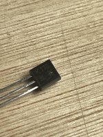
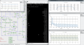
Error: Cannot add Q1 (footprint “Package_TO_SOT_THT:TO-92_Inline” not found).

Total warnings: 0, errors: 1.
Error: Errors occurred during the netlist update. Unless you fix them your board will not be consistent with the schematics.

The following is the version information:
Code:
Application: KiCad
Version: 5.1.9+dfsg1-1, release build
Libraries:
    wxWidgets 3.0.5
    libcurl/7.74.0 OpenSSL/1.1.1n zlib/1.2.11 brotli/1.0.9 libidn2/2.3.0 libpsl/0.21.0 (+libidn2/2.3.0) libssh2/1.9.0 nghttp2/1.43.0 librtmp/2.3
Platform: Linux 5.10.0-14-amd64 x86_64, 64 bit, Little endian, wxGTK
Build Info:
    wxWidgets: 3.0.5 (wchar_t,wx containers,compatible with 2.8) GTK+ 3.24
    Boost: 1.74.0
    OpenCASCADE Technology: 7.5.0
    Curl: 7.72.0
    Compiler: GCC 10.2.1 with C++ ABI 1014
Build settings:
    USE_WX_GRAPHICS_CONTEXT=OFF
    USE_WX_OVERLAY=ON
    KICAD_SCRIPTING=ON
    KICAD_SCRIPTING_MODULES=ON
    KICAD_SCRIPTING_PYTHON3=ON
    KICAD_SCRIPTING_WXPYTHON=ON
    KICAD_SCRIPTING_WXPYTHON_PHOENIX=ON
    KICAD_SCRIPTING_ACTION_MENU=ON
    BUILD_GITHUB_PLUGIN=ON
    KICAD_USE_OCE=OFF
    KICAD_USE_OCC=ON
    KICAD_SPICE=ON

Testing 8045G Tubes on a Heathkit IT-17 without scroll data

The Heathkit IT-17 tube tester has a section on testing unknown tubes; it ways to hold the line adjust short test switch in the test position, and adjust the plate control to bring pointer to the middle of the good scale. Is there a more accurate way of testing the plate setting on my tester? Perhaps setting it to the same number as a similar tube?

For Sale 12V 2A external linear PSU, ultra-low noise

New in box: 230VAC to 12VDC external linear power supply, ultra-low noise. Voltage is fine-tunable with a screw on the back side. Maximum current is 2A. Asking price: € 70, shipping from The Netherlands.

Outputs:
  • 2x 5,5 x 2,1 mm jack plug
Of Chinese make but with high quality components:
  • Talema transformer
  • 4x high speed diodes
  • Philips filter capacitors primary side
  • Panasonic FC and Siemens filter capacitors secondary side
  • includes EMI filter
Dimensions (b x l x h): 102 x 150 x 60 mm
Weight: 1,1 kg

Also available in 5V.

Image uploads are somehow not working, here are the pictures:

DIY RCA Switch Box - Common vs Switched Grounds

Hello everyone! I recently built a small sound system in my office with passive Edifier P12s and an old subwoofer, powered by a Fosi Audio BT30D. My sources are an Echo Dot with a aux jack to RCA cable as well as an Audio Technica AT-LP60X-BK turntable. It works and sounds great, but my the BT30D only has one set of RCA jacks, so whenever I want to listen to a record instead of streaming music, I have to open my cabinet and manually switch the RCA jacks.

To that end, I need an RCA switch. I was originally looking at the SOLUPEAK S1, but it's a bit expensive and it seemed like an easy enough project to build on my own. My biggest issue is that I'm not sure whether I should tie my ground together, or if I should switch them along with the RED and BLK lines. I've attached two schematics to illustrate the two different designs. I've seen several threads about doing exactly this, and it seems like most people use common grounds and only switch the RED/BLK lines. I don't think that would cause any issues, but I'm very far from an expert on electronics/audio equipment.

So, diyAudio, what do you think? Should source grounds be common or separately switched? Please provide some reasoning as to why you believe it should be one way or the other.

Attachments

  • Common Grounds.png
    Common Grounds.png
    50 KB · Views: 760
  • Switched Grounds.png
    Switched Grounds.png
    55.4 KB · Views: 680

Importing drivers from Germany to the USA.

I am in India, and previously imported a pair of drivers from Germany, directly to India... it was tremendously troublesome, with customs and bank requirements... A year down the line, I'm still being asked to submit some documents (I did take delivery after a couple of weeks of haggling with customs).

I want to import a pair of drivers into the USA, from where I have friends coming to India on a regular basis.

What is the customs situation in the USA for stuff like this... Assume the value is 700 Euros, for the pair..., how much will I have to pay for Customs clearance?

Thanks,

Sonus Faber Concerto and Grand Piano Speakers for Sale

Sonus Faber Concerto and Grand Piano Speakers for Sale. Circa 1999 -2000.
In good condition and sound great. The Concerto monitors include metal stands and are bi-wire and bi-amp capable. Baffle driver arrangement is mirror image.
Grand Piano floor-standing speakers have out-rigger spikes. Grand Piano are a single speaker connection type.

Concerto monitors are $800 pair.

SOLD Grand Piano floorstander are $800 pair. SOLD

Pickup only.
No crate or boxes available.
Located outside Philadelphia in Wayne PA.
Selling because I'm moving into smaller home.

Currently on sale at usaudionmart.com.

Thanks for looking.

Vince

Attachments

  • 20220601_201749_resized.jpg
    20220601_201749_resized.jpg
    225.7 KB · Views: 242
  • 20220601_201757_resized.jpg
    20220601_201757_resized.jpg
    197.8 KB · Views: 216
  • 20220601_201805_resized.jpg
    20220601_201805_resized.jpg
    294 KB · Views: 208
  • 20220601_201915_resized.jpg
    20220601_201915_resized.jpg
    222.3 KB · Views: 205
  • 20220601_201925_resized_1.jpg
    20220601_201925_resized_1.jpg
    244.7 KB · Views: 209
  • 20220601_201935_resized_1.jpg
    20220601_201935_resized_1.jpg
    161.4 KB · Views: 212

Premium ACA with CapMX PSU with idss matched pair of 2SK170BL

2x Premium ACA boards with CapMX PSU onboards with the required matched pair 2SK170BL idss 6.3

£40 for the lot postage included

for more info: https://www.diyaudio.com/community/threads/premium-aca-with-capmx-psu.347732/

Attachments

  • IMG_5493.JPG
    IMG_5493.JPG
    563.4 KB · Views: 151
  • IMG_5494.jpg
    IMG_5494.jpg
    779.7 KB · Views: 171
  • IMG_5495.jpg
    IMG_5495.jpg
    653.5 KB · Views: 151

no sound in output of DAC

hello,

i'm installing Mood Audio Player on raspberry pi 3 whit a DAC audiophonics Sabre 9023:
AUDIOPHONICS DAC Sabre ES9023 V2.2 I2S vers Analogique 24bit/192kHz - Audiophonics

I have setted the OS mood after have connected raspberry pi 3 to DAC ...
I have succeeded in controlled the raspberry remotely with diyAudio server HTTPS page (wireless)
I have succeeded in product sound by hdmi
But i am blocked when i want product sound by i2S output of the DAC ...


I have restarted the system for save the configuration many times ...
If you have ideas ... suggestions ... ?


An externally hosted image should be here but it was not working when we last tested it.

An externally hosted image should be here but it was not working when we last tested it.

An externally hosted image should be here but it was not working when we last tested it.

An externally hosted image should be here but it was not working when we last tested it.


PS= relied in Double RCA to Jack 3,5 (little jack) on my ampli

Class A and Pass amp questions

I built an ACP+ to use as a preamp (to go with the B1 and DCB1) and it is glorious. I've got a lot of experience with class AB and class D amps, but less with class A.

The ACP+ has definitely made me think about building one of Nelson's amps.

At our house, we start out the day by turning the system on and then making coffee. You have to have your priorities.

The ACP+ definitely sounds best when warmed up, but is still workable right away.

Would a full sized class A amplifier operate the same way (decent sound at first, best when warmed up) or would there be a waiting period before we could play the amp?

We are running Elac Unifi UF5 (first series) speakers, which go down to 4 ohm and all of 85 db efficiency. I am not particularly worried about volume as we are using a NAD C326BEE and it has plenty of power and I have put smaller amps on it yet and been fine. While there are occasional drunken Friday's where we play the Dead at full volume, that is not the case 99% of the time.

I was thinking about either the M2x or F6 because of their ability to run 4 ohm. My tastes run toward a warmer and romantic sound rather than brighter and more analytic.

Would the M2x fit better here than the F6?

Does anyone know the power consumption of these amps at idle?

I live in a part of the world that is genuinely cold (-35F/-37C being the coldest I have experienced while living here), but it is also very warm in summer (up to 100F/38C), so heat production would probably limit use of class A to winter, but it would be good to know roughly what kind of power the amp will consume.

Thank you for any information you can give!

Cambridge Azur 640A V1 Buzz

Still working on other stuff on this forum. Thought the following would be a no brainer. Sigh... 🙂

Looking to fix my son's integrated. It buzz's upon start-up then (mostly) goes away after about 30 minutes.

Buzz is there without any signal, only speakers hooked up.

Observed that if you turn the volume up, the buzz disappears around the 9 to 11 o'clock area, then starts again.

I have tried cleaning the volume control pot, and all other pots for good measure to no effect. (MG Chemicals zero residue spray)

I still thinking the volume control, but weird that after warm up the buzz fades.

Any help would be appreciated.

Ed

Waveguide "acoustical loading"

Hi,

Thanks for reading my post.

I came across something that I don't know how to "translate" into the real world.

On parts express, there is a waveguide that has a minimum frequency response. I notice that every waveguide has a frequency range listed.

My question is about what happens if a speaker is crossed below the "minimum" that is shown for the waveguide.

Is that where the "honk" sound comes from in horn drivers? I mean, is that honk created by improperly matched crossover frequencies on those drivers? (edited: because this was me rambling)

This is the waveguide that got me to thinking about it: https://www.parts-express.com/Dayton-Audio-H08RW-8-Round-Waveguide-1-3-8-18-TPI-270-308

Thanks again for reading my post.

Dan

Classical music anyone?

Hey everyone, I was wondering if any of you listen to classical music, maybe opera? I'm a huge fan of Renee Fleming, who is an amazing classical singer. So I'd thought I'd share this info with all other fans or anyone who's interested. Universal is auctioning off signed CD's of Renee's BY REQUEST, it's available at http://www.universalmusicstore.com/reneefleming

if you're interested, please go and support her! Thanks everyone, i'm sure you will enjoy this great cd!

😀
  • Like
Reactions: mp9 and head_unit

Installing and using ngspice - an opensource simulator

ngspice - an opensource circuit simulator - should have it's thread to discuss some basics from installing to simulate a complete amplifier.

Attached a picture with ngspice version 30 in action.

This first post will be updated from time to time.

BTW: ngspice V30 manual (v30 has been released 01.01.2019) contains Dave Zan's IXTH48P20P model as a VDMOS example - p146. :up:


BR, Toni

Attachments

  • Screenshot_20181225_230246.png
    Screenshot_20181225_230246.png
    265.7 KB · Views: 1,441

Help restoring Marantz 6370Q

Where to start....
Years ago I bought a dead Marantz 6370Q for parts without the arm and a few other bits (legs comes to mind) and on top of that it was damages a bit more in transit but only cosmetic but at least it was cheap.
To start I bought some Technics 1210 gel feet/legs and they were a strait fit so no issues there and 1 issue solved.
Next in line was the tone arm and I find out that finding an original Marantz/Jelco arm for this TT is close to impossible so I went ahead and fitted my vintage SME 3009 to it and removes the auto functions for the original arm (have that subchassis stashed away).
Perspex lid was missing so used the one I had and it does the job.
Now I call this little gem my Frankenstein and it sound beautiful...
So lets go to the "cosmetic" part of it
Anybody know where I can get a Fascia for 6370Q in good condition ?
I can live with the issue but if I could find one for a reasonable price it would be great.
(yes I looked online but didn't found anything)
Any help is appreciated.

Analogue line level hafler circuit (surround from 2ch)

Hello

Using 1:1 15kOhm line transformers salvaged from standard audio ground loop isolator filters and a bunch of 10kOhm resistors one can put together a crude yet functional and experience boosting surround "decoder" generating both rear and centre mono channel line outputs from standard 2ch stereo speaker level inputs.

This is far from a new approach, and I'm sure you guys here could draw a correct schematic in dark if so inclined, in its basic form these circuits are very simple.

But now I'm wondering if there is a way to get rear right and left channel separation as this signal is in its basic form simply the difference between the left and right channels, a mono signal, one channel, but I'm not sure how to accomplish this, perhaps mixing in a bit of the original left channel in the rear left channel and vice versa, could this work?

This circuit is completely passive, only transformers and resistors are used.

I will post some schematics later to aid understanding.

Help me with this date code

Hi!

I have some TI NE5534P opamps I bought years ago, with the following date code: 84AJL3M. The TI datasheet does not make it clear...🙄

On semiconductor also makes their version of the NE5534P. And on their datasheets, they specify the date code. Despite being in another format, the first two numbers MAY specify the YEAR of fabrication, but i'm not sure at all. This is why i ask here. ¿Is this opamp from TI (texas instruments), from the year 1984?

Thanks a lot!!

Jay x

Output Mosfets on A75

After 13 years of reliable and pleasing operation, my A75 started to make crackling sounds, faintly on the left but strongly on the right channel.

After replacing all caps except for the big cans - they measured like new - everything was ok for a few weeks, then the noises came back.

Now that i´ve replaced all trimmpots and started re-commisioning, on the first channel 2 output FETs (IRF630 by IR) have 2x resp. 3x more bias current than the other 10, whose currents are quite close.
On matching back then, the 12 N-FETs had 3,43-3,44V UGS at 180mA.

Now i´m wondering if this is normal MOSFET behaviour, aging, brand-dependent or whatever. So if anybody could share their experience, i´d be glad to hear.

Thanks
Norb

Small Apartment Speakers Setup

Hi Friends,

I am asking for your suggestions of a better location/arrangement to set up my speakers.
Right now they're sitting on top of a study desk that folds out and I listen near field. I have a pair of small bookshelf (3 inch midwoofer) and a 12 inch sub. Depending on the space and possible setup, I either go full stereo and build a new pair with 6 inch woofers, or stay 2.1 with a 8 inch sub for better integration with the mid.
Since you guys are taking the time to help me, I make it easier by providing an up-to-scale drawing, showing my current setup. The bedroom is off-limits but the living room is quite flexible at the moment. Glass surfaces are marked in blue.
If more info about the room is needed please let me know. I am open to any suggestion for the best musical enjoyment. Thanks in advance!

Attachments

  • Current Layout.png
    Current Layout.png
    10.3 KB · Views: 197

15" woofer in <100 Liters with sensibility >95 dB

15" woofer, what about Faital 15FH500 (or 520) ? listening impression ?

Hello Evryone,

I have done my choice on my design. A 4 ways 15"/12"/6.5/Tweeter.
I have the medium and the tweeter, for now a couple "PR170Z0 + HT958PA" and another couple "PHL 1140 + tw034". And in the future, an AMT Heil ESS 🙂
My choices were driven by size and sensibility

So well I'm looking for a good woofer, with sensibility close to 95 dB / W / m, inside less than 100 Liters. Can you help me please ?


For now, I have two faital on my short list : 15FH500 and 15FH520. Any opinion about them ? listening impressions ?

By the way, how to choose between thme ?

Thank you in advance !

Does Linux have to be so frustrating?

I'm not that kind of conspiracy follower and definitely not technophobic. I just don't use more technology than I need... My -not a smartphone- cellphone is already 12 years old and comes second to my 15 years old PC! The later starting with WinXP and lately moving to Win7 run without any sign of deterioration until 5 days ago. Then black screen and it refused to boot. First thought was that the mobo hit a record and it deserved a place on the "wall of fame". I ordered new parts to rebuild the machine in the same case 🙂 but just before disassembling the old I tried it off line... and it boots:scratch1: Anyway, I proceed to the new built. New hardware is compatible only with Win10/11 so, this is my adios to Microsoft once and for all! I'll keep a sweet memory from early days of WinXP and that's all!

New entry, Linux Ubuntu! I've tried this before for fun but never as my main machine. I can see it is improved now.👍Actually, impressions are mixed... It runs fast and flawless for "native" applications and these cover almost everything and then it comes to some minor details that make it PIA to use. Changing keyboard language from English to Greek is a daily routine for me but now I can't do it in one sentence... And my printer is recognized but not printing... And my scanner is not recognized at all... And there are countless sites about "troubleshooting for beginners" that do not look like that in the eyes of a newbie...

That said, I'm willing to stay with Ubuntu! I may bother you with some naive questions and the foreword was to let you know that I'm even more clueless with this than with audio electronics...
  • Like
Reactions: weissi

Avalon VT-747sp Module

Some products are hard to find teardown images, and Avalon is one of them.
I recently found these images of the VT-747sp and noticed this small module mounted on a small pcb called "Avalon AD2101".

It is used on all stages, inputs and outputs, eq and compressor.
Is that a small buffer?
Did anyone already know? Have you tested?

I appreciate any information.

Attachments

  • avalon input-output.JPG
    avalon input-output.JPG
    531.9 KB · Views: 235
  • avalon eq01.JPG
    avalon eq01.JPG
    476.9 KB · Views: 205
  • avalon eq02.JPG
    avalon eq02.JPG
    634.1 KB · Views: 251

For everyones information on the word "Aleph" and delayed PP payments

This is just for information purposes for those who use PP when buying / selling Nelson Pass components from the Aleph lines. If you include the word Aleph in any part of the PP transaction, PP will hold up the payment for a minimum of 24 hours, sometimes up to 5 days, and sometimes they will decline the transaction. They say it is for security reasons.

It is not due to the standard meaning of the word in the Hebrew alphabet, but rather due to the word also being the name of a Japanese doomsday cult. Quite a stretch on the part of PP, in my opinion.

Anyway, to save yourself headaches, do not use the word Aleph in PP transactions.

Moderators feel free to remove this discussion if it is not pertinent to this forum.
Projects by fanatics, for fanatics
Get answers and advice for everyone wanting to learn the art of audio.
Join the Community
507,685
Members
7,884,223
Messages

Filter

Forum Statistics

Threads
406,035
Messages
7,884,223
Members
507,685
Latest member
EvenLouder