WAW / FAST MTM MLTL crossover point/s

Evening Gents

Is it possible to have a FAST MTM MLTL speaker using two 6.5" woofers with a small fullranger and vary the crossover point depending on music played, say if using the MA 7.3, from 120 to 320 hz allowing one to optimize for the genre of music being played or does bsc have to be built in to the design thus determining physical dimensions resulting in only one crossover point that works?

Thanks,

Sheldon

Test equipment for loudspeaker measurements?

Hi all,

what test equipment is recommended for meusurements of speakers to tine tune the design (open baffle --> shape) and crossover design?
I already bought a mic (omnitronic mm-1c) with stand.
I want to do the measurements with my laptop, so I need an audio-interface for output (ideally cinch) to amp--> speakers and input for the mic.
Most audio interfaces with mic preamp seem to have only line (6.3 mm) in/ouputs but not cinch.
What is better: "Standalone" mic-preamp and very simple audio-interface with cinch, or an audio-interface like Steinberg ur12?
Are the outputs independant so that I can use them for the e.g. sweep output and record the mic simultaneously?

6N15N-EB confusion

Hello to all, I have a Hughes & Kettner 25th Anniversary guitar amp that came stock with 6n15n-EB tubes and one has a crack in the glass and it still functions but I don't trust it. I bought the amp used from the original owner and it is like new and it has never been apart so it must've come this way from the factory. I understand that these are not EL84 tubes yet H&K says the amp has EL84's. I called H&K to get a replacement and they said to use any EL84 tubes. Terrible customer support lacking any details. They rarely answer email. The earlier versions of this amp both had EL84's in them. I don't know why they used these 6n15n-EB tubes instead of regular EL84's but they do brag about them in their advertisements as hand picked military top drawer tubes, and they do seem to sound pretty good. I would however like to try some EL84's like JJ Teslas to compare the sound but I'm not sure if standard ones can handle the 400V plate voltage that I've read this has. It seems that most standard EL84 tubes can only handle 300V max. I can't find any spec's on the 6n15n tubes to see if they are rated higher than 300V and I don't know what type EL84 tubes the earlier version amps came with. I'd like to know if I can go with standard EL84's or if I have to limit myself to the small amount of higher voltage ones available, or should I just stay with the 6N15N-EB type even though they seem to be difficult to find and maybe not as desirable as EL84's for guitar tone. Thanks for any input.

Arcam A70 can't adjust bias

Hi guys.
I need help with the Arcam A70.
The amp runs very very hot. Bias is 250-300mV for both channels and does not tolerate adjustment.
There is no service manual for this model, but there is one for the A80, which according to some users is the same as the A70, but with a larger transformer.
What do you think the problem might be? I read that it could be the emitter resistors that are built into the SAP15N/P transistors.

scheme for A80:
a80_SM  ====== A70 was an A80 with a smaller power-transformer_011.png

PAM8406 (and PAM8403)

I had a need for a 5V amplifier, and a quick search showed the easiest commonly available module is based upon the PAM8403, and cost about $0.50 per unit.

10 Pcs PAM8403 2X3W Mini Audio Class D Amplifier Board 2 5 5V Input US SHIP M323 | eBay

Having played with these for a few days now, I can safely say, if you only need a few watts, you will not find a better amplifier for under $1.00. The sound is very good, and the board layout is not terrible. However that is not what this thread is about, just a bit of back story.

After being very satisfied with these I looked into other Diodes inc PAM based amplifiers, and discovered the PAM8406 which is pin compatable, supports down to 2R loads at 5W/ch running 5V. That is all well and good, but you might be saying "I don't use any 2R speakers that will run well at 5W", and you would be correct. The real thing about this chip that caught my eye, was the "mode" selection that the PAM8403 does not have. This chip can be operated in Class AB mode!

After inspecting the layout for the $0.50 boards, I found the mode pin (listed as NC for PAM8403), is already tied to ground, so a simple chip swap will give a PAM8406 amp ready to run in Class AB. So that is what I did, and I can report that it is a fairly significant upgrade from the PAM8403, at the cost of a much lower efficiency.

Now, since this chip is such a simple layout, I thought maybe I can do better, which brings me to the real reason for this thread. I have done an initial layout for a PAM stamp, and would like some feedback. I based my layout on the Chinese board, but made several improvements.

1.) Increased input decoupling. Was already fairly good, but can always be better.
2.) Eliminated external 10kR resistor from input, instead relying on input impedence to form the input filter.
3.) Added ground plane everywhere for noise suppression and EMI
4.) Added ferrite bead filter on the output for EMI
5.) Cleaned up the input and output headers (IMO, this is a personal preference thing)

Please note in these photos, the signal input ground should connect to the ground planes surrounding it, I need to fix the copper there. The bottom of the board is a solid ground plane.

Would love to hear the opinion of those with more experience laying out boards, I basically have no clue what I am doing. I will try to get some high res pics of the Chinese board I started with for comparison tomorrow. I can post component values for the passives if anyone wants to know.

Attachments

  • PAM8406.PNG
    PAM8406.PNG
    74.9 KB · Views: 1,613
  • PAM8406 Copper.PNG
    PAM8406 Copper.PNG
    25.2 KB · Views: 1,421
  • PAM8406 Mask.PNG
    PAM8406 Mask.PNG
    20.8 KB · Views: 1,383

Osprey-BR parts Eminence Beta 10CX and Selenium D220Ti and crossovers

I have
2) Eminence Beta 10CX
2) D220Ti
2) completed crossovers
with a few weeks use.
$450 $425 $400 includes shipping within continental US. (ships from Northern California)

https://ampslab-spk.com/2021/04/25/osprey-br/
If you email him he will send build plans for the box.

pictures added below.

feel free to make an offer, especially if on the west coast where shipping would be cheaper.

For Sale Two Crossover PCBs for Liionidas Open Baffle speakers, boards by Ale Moglia of Bartola Valves

SOLD

Alas, another project that will not happen.

Asking $40 $30 for the pair, including shipping to Continental USA

If you are contemplating building the Liionidas Open Baffle speakers, I have two crossover bare boards for super premium part mounting as designed by Ale.

Liionidas speaker link:

http://www.modelpromo.nl/audio-dandy/reviews/The Liiondias Open Baffle Speaker/The Liionidas Open Baffle speaker.pdf

Each board is 198 x 120mm.

It calls out for

Jantzen C-Coil Torroidal Inductors
Mundorf M-Cap Evo-Oil Cap
Mundorf M-Resist Supreme 20W Resistors

I will include for the new owner my correspondence with Ale about the crossovers and boards.

IMG_0714.JPGIMG_0715.JPGIMG_0716.JPG

  • Locked
For Sale Class A FirstWatt F3 amplifier

I’ve stayed long on this and built it many years ago and I must tell it has served me well and still operates as expected. This amp is 12W class A - single ended, 10k input impedence m also it’s Power JFETs on the output.

Then a little building details it’s has 5U chassis
with Dual mono power supply (2x 300VA transformers, and 68000uF capacitance per channel in CLC configuration. Includes Soft start circuit and it’s built on High quality parts.

I’m interested in selling it for $1200

USB Audio interface for measurement

Hi All,

I've been inactive in the DIY speaker world (and on this forum!) for a few years but time and opportunity has finally come to finish some speakers that have been half finished in bits in storage for years for lack of time, working space and money... 🙂

Years ago (since 2003) I used a Desktop Windows XP PC with a Sound Blaster Audigy 2 ZS as my measurement card - one of the few prosumer cards in the early 2000's that supported true 24 bit 192Khz recording and playback without re-sampling and had very good analogue performance, and I used it extensively for speaker / crossover measurement with various software including most recently ARTA.

Unfortunately in the last year that PC has gone belly up, and as the card was an original 32 bit PCI card that most PC's today won't support I can't really put it in anything else, even if I had another desktop PC to put it in...

Besides, it was very inconvenient using a large, noisy desktop PC for speaker measurements!

Nowadays I use a Windows 7 Laptop but it only has a single shared mic/speaker socket, and even if it had both I'm sure the quality would be dreadful compared to my old card anyway and inadequate for precise speaker/crossover measurement.

So I'm in the market for a USB sound card, and my requirements are:

1) Preferably under £100, in the UK.

2) Full duplex, naturally.

3) True 192Khz 24 bit without any re-sampling or other post processing, and the flat frequency response and low distortion/noise floor that you would expect of a good quality 192/24 card.

4) Must work well with ARTA.

5) Inputs that support both XLR with phantom power for the measurement microphone, and line level input for direct connection to crossovers, making impedance measurements etc.

6) Inputs must be fully independent - eg independent selection of XLR or Line, independent gain control etc.

This is important to be able to make proper use of dual channel mode in ARTA - typically you would connect the measurement microphone to Left in XLR mode with phantom power, and connect the right input in line level mode (possibly with a suitable L-Pad) to the input terminals of the speaker to cancel out any response errors in the amplifier, random delay variations in the sound card that might affect phase measurement etc.

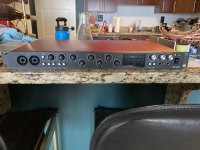
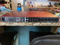
I did a quick 10 minute browse tonight and came across one promising candidate at about half the maximum I'm prepared to spend, the Behringer U-PHORIA UMC202HD USB Audio Interface:


Behringer U-PHORIA UMC202HD USB Audio Interface | DV247


It seems to meet all my requirements above, and seems almost too good to be true for the price. Is it ? (Or have things just moved on a long way in the 10 years since I last looked at USB sound cards!)

The only thing it seems to be missing that would be good is a "high impedance" mode for the inputs, which would be useful for more accurate measurement of crossover outputs without loading them down, and also be necessary for impedance measurements.

I'm assuming it will have an input impedance of about 600 ohms or so in line level mode ?

Another interface that does have a high impedance mode for one of its inputs and thus would be better for impedance measurements and direct crossover measurements is the Steinberg UR-22 MkII:

Steinberg UR-22 MkII | DV247

It's also pretty similar in other regards, however it's about twice the price.

Am I going to run into problems with impedance and component measurements without a high impedance mode ?

I don't have access to an RLC bridge anymore so I would quite like to be able to measure crossover coils and caps (mainly coils, as my multimeter can do caps) using ARTA as well using an RL / RC test configuration.

Any thoughts and an opinions of these two boxes, or recommendations of other ones to check out in my price range ?

On a related note - in the house I currently live in I won't be making most of the measurements in the living room (not enough reflection free window time) and whilst my laptop and a USB interface are far more portable than my old system for measurements I still have the issue of the amplifier.

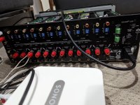
I now only have one amplifier and it is well and truly fixed in place in the main AV cabinet, getting it out to take to another room to do speaker measurements would be a major PITA.

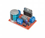
So it occurs to me that a small, portable amplifier that I can use with the USB audio interface purely for the purpose of driving a single speaker to take a frequency response measurement would be extremely handy, if not essential.

It doesn't have to be fancy - it doesn't really need anything more than a volume control, doesn't need to be stereo, doesn't need tone controls, lights etc. What it does need is very flat frequency response, low output impedance and an output of about 10 watts. Something that is not much bigger than the USB audio interface would be great, as together with the laptop and USB audio interface it would make it possible for me to measure just about anywhere including the holy grail - outdoors!

Is anybody using a small portable amplifier for measurement tasks and have a recommendation ?

Looking for a nice 50-100W Class AB Amp design with Onboard PSU

Hi
I am looking for a small class AB or B Amplifier with around 50-100W with an onboard PSU where I only need to connect the transformer and do not need a separate PSU. The idea is to convert my nice small studio monitors from passive to active. Each Speaker would have his own mono Amp, and the Filtering will (in this case) be passive. I tried with class D modules but I miss a bit the musicality. Class G would also be OK. If the PCB artwork has already be done, even better as I am not the master PCB designer.
Any suggestions would be warmly welcomed.
Best regards
Christoph

Building a Dynaco PAS4 clone

A long time a go a friend made a comment about the Dynaco PAS4 that the triodes on a ECC83 was parallelled. He did not understand why, i did neither
at the time. Now i know better.
The issue has been a thorn in my mind, especially as none of these amps
ever came to sweden, thus we had no experience of the amp and could
not say if it was good or bad.
A few years ago in a discussion with roy mottram a decision was to
make a few boards, i eagerly bought one.
Now time has come to realize this amp.

See Dynaco PAS4 klon where the build process is documented.
( it is a test-features amp, not all features will be implemented at this time)
Anyone with experience of a read PAS4 is welcome with experience of
a real pas4. Everyone else is of course welcome with comments.
One detail has interested me : the loop output.

The loop is a way to loop the signal thru an external tonecontrol box or
equalizer , where the loop itself is enabled with a switch. Thus for anyone
that don't want tonecontrol will not connect anything here. Others can
buy or build a tonecontrol box, connect it and use it at will. The nice with
this is that one can always disconnect the tonecontrol with a switch when
it is not wanted.

I have populated the board, done some repairs and slightly changed the
circuit by a few LED used to bias instead of the original somewhat
"kludgy" way of obtaining a small negative voltage.

Within a month i hope to have the box ready for use. I'll update the above
link as build progresses.

Beolab 6000 - repair, Bluetooth conversion and damping upgrade - Basotect?

So I was taking my daily walk a few days ago and stumbled upon some discarded Bang and Olufsen Beolab 6000 speakers.

One had been kicked over and lightly urinated on by a local fox and considering where I live London I was surprised this was the limit of neighbourhood interference. Rule of thumb around here is, if its not bolted down its stripped for parts and then what’s left is set alight, I suspect the rain that day slowed proceedings.

FE44A4A7-21D8-4291-8D8F-E407F2027C48.jpg

2A6D3385-EF9E-4446-BB5E-A0E5F9C09997.jpg

It seems they were discarded as they has suffered which now I understand to be a common problem of cracking rubber speaker surrounds.

ED7F18C4-DA1E-48C4-A455-6D854C9792B7.jpg

As they were wet, dirty and smelling of fox urine I decided to strip them down, dry out the damp electronics and then wash the contaminated parts. Turns out the scent of a fox is very tricky to get rid of, something I hadn't anticipated.
Once dried with a hair dryer it was time to move onto testing them.

291DEC6F-FE59-4CAB-B7E3-86705ED3A2D7.jpg

844001B4-5D29-45CF-B4FB-582DC32F4D64.jpg

491083BE-2E94-4D63-BD86-DBBF19F32967.jpg

When launched in 1992 these speakers retailed for $2500 which is an incredible amount of money considering, although they seem to be well made using a cast aluminium chassis which doubles as a heatsink, fibre reinforced composite for the driver and tweeter housing and branded components for example Hitachi wires and Elna caps.

Both speakers are working so I ordered some replacement rubber speaker surrounds from Audiofriends in the Netherlands, the kit includes 4x surrounds, glue and fitting instructions for £24 including delivery, very reasonable. These replacement rubber surrounds apparently also add a little extra bass, I’m not sure how though.

I then proceeded to remove the old surrounds and adhesive in preparation.

5F3AA521-5944-4EF7-AB48-DD7479E4F00C.jpg

B969E40C-8150-444A-B95B-B13AB3FE70A5.jpg

Having used Beolab 8000’s in the past I’m fully prepared to be underwhelmed by these speakers, however in London space is a premium and these speakers would would work well as bedroom units given the small footprint and active design.

I have a Bluetooth 5.0 module lying around and noticed that it would fit perfectly attached to the back of the MOSFET unit, the screws are correctly spaced and the threads are the right diameter with some spacers to move the board off the back of the MOSFET unit and with longer screws to accommodate the spacer it should fit well (could the switching frequency of the mosfets effect Bluetooth?..

There’s a few challenges to overcome, one will be finding a 12v - 24v DC supply from the board, ideally I’d like to fit the module with minimal hackery so as to keep the speakers looking stock externally.

C8CCCDCE-41B1-4FC0-AFCE-5D2232574D16.jpg

These Bluetooth modules have an auto sensing line-in input meaning the aux input on the bottom of the unit can be retained keeping inline with my minimal hacking ethos.

The second somewhat easier challenge is routing the second channel of the Bluetooth DAC module to the other speaker whilst also retaining the aux input. As I understand it these speakers can be daisy chained using the B&O power link connector (a proprietary DIN based connection) but this only works when a B&O preamp with a power link connection is used. On the bottom of each speaker is a toggle switch which allows setting to left or right depending on the positioning of the speaker within the room.

When using something other than a B&O source with Powerlink, each speaker would then have to be sent one channel each using an single channel RCA, as each speaker has a a single RCA aux input. For example the left speaker is fed a the Left channel using an RCA cable and the right speaker is fed the Right channel using an RCA cable.

My assumption is that it would be tricky to utilise the Powerlink connection as my interconnect whilst still keeping it working as a powerlink connection as it’s proprietary. As I don’t have any B&O sources and don’t intend to I guess I can remove the connections on the internal amp side of it and just use it as a DIN based interconnect assuming I make modifications to the other speaker.

My question is, what would be maximum cable run I could use to send that line level signal from the tiny Bluetooth DAC module to the other speaker? I presume a few meters will be fine.

Whilst looking inside the speakers I noticed a severe lack of damping material. My knowledge on this area is limited but I suspect due to the small internal volume of these speakers (3 litres) any extra damping would reduce the internal volume too much, hampering the already limited bass performance. Would adding something like thin layers of basotect (cut up magic eraser) instead of the grey foam already in there improve things at all. I’m not sure what I’m looking to improve to be honest, maybe reduce any resonance of the aluminium housing?

50F69F80-ED43-4696-BD4F-5573B4044D14.jpg

Lastly I’ve ordered some adhesive backed foam tape to replace the horrible disintegrated stuff in there. Apparently a known fault with these speakers and beolab 8000’s is something coined as foam rot.

Help Quad 33 and 303 setup no right channel output

I have recently purchased a quad 33 and 303 in original condition.
The only problem is that i am not getting right channel sound.
I have ruled out cabling issues.
I am connecting to tape replay using an rca cable to DIN which i connect to my laptop.
I have tried all stereo left and right buttons. but simply not getting audio from the right channel on the 303. The speakers work.
I am going to confirm soon to rule out the 33 by measuring the output from the 4 pin DIN output cable.
I've opened up the 303 and the only obvious issue i can see visually is the C104 cap on the left driver is blown (as in the top casing of the capacitor is gone and i see the yellow internals) but the left channel works. the right channel driver components look fine. everything else also looks fine visually

Please could you provide a fault finding instruction to identify the fault causing the right channel not to work?

any help would be appreciated

Would my existing JBL Enclosures be suitable for 2216nd or is this a crazy idea?

Hello,

I was hoping for some advice as I may be above my head in my enclosure knowledge.

I have some AM6200/95 Mid/High compression horns which I like the sound of, and I sat them on top of some existing JBL bass units I have.

These are the JBL 4637 - not to be confused with the much more expensive 4367
https://usermanual.wiki/JBL/4637.1891637758

These are made up of a 2035HPL driver in a C4507 cabinet - cabinet info here:
https://jblpro.com/en/products/4507-4508-4518-4550bka-4560bka

The bass response sounds a little sloppy now compared to the mid/highs on top, which are a much higher grade speaker from JBL.

My question is because I don't understand enclosures enough to know if this is a crazy idea, but I can easily buy some JBL 2216nd which I know are great models as per the M2 and funnily enough a variant is on the 4367.

I think the 2035HPL can be swapped for a 2226H without issue, and I saw mention of using a 2216nd instead of a 2226H in many threads which got me thinking.

I assume I would get a much better response immediately than the 2035HPL, but I don't know if my enclosures can 'handle' it.

The enclosure specs as per the link:
Lowest Usable Frequency - 40 Hz

Q
500Hz - 4
800Hz - 8

140L - 5 cu ft

546 x 775 x 448 mm

Not knowing about enclosure design I wondered if anyone could tell me if this was an insane idea.

Speakers would be for general purpose stereo use, movies and music.

Thanks for any help!

Phase noise in DS dacs

In the thread (now closed) "The battle of the DACs, comparison of sound quality between some DACs" there was some discussion (or debating) about the impact of close-in phase noise on DAC output.
One way to measure the phase noise is to look at the noise skirts in FFT spectrum as JosephK did here: https://www.diyaudio.com/community/...jitter-crystal-oscillator.261651/post-6710439. This requires a very small bin size. I decided to make similar measurements with REW albeit the FFT size in REW is limited to 4M. But anybody with REW, DAC and ADC can repeat these measurements.
I used my own boards for the measurement:
  • AK4490 DAC
  • ES9822PRO ADC
  • USBI2S bridge
The master clock was on ADC board and DAC used the same clock.

First 11.025k sine of -1.5dBFS at 44k1. This uses 22.5792MHz ECS-2520MVLC clock having phase noise in datasheet as -89dBc/Hz @10hz (https://www.mouser.fi/datasheet/2/122/ECS_2520MVLC-1903379.pdf).

AK4490_ES9822PRO_11k025@44k1.png

Note the horizontal scale (+/-10Hz). Not bad for a $1 clock.

Next up 12k sine of -1.5dBFS @48k. This uses a 24.576MHz NZ2520SDA clock with presumably lower close-in phase noise.

AK4490_ES9822PRO_12k@48k.png

Clearly better but whether or not audibly better is another story.

Besides clock there are other factors that affect phase noise. One is Vref. In my AK4490 DAC Vref is fed by LT3042 regulator (separate L/R).
Here is the same measurement as above but with slightly altered Vref implementation.

AK4490_ES9822PRO_12k@48k-X5R.png

Clearly much worse and a much bigger impact than clocks.
The only difference between graphs 2 and 3 was that Cset capacitor of LT3042 was changed from 22uF/15V tantalum polymer to 22uF/25V X5R. The result is understandable as Cset affects the 1/f noise of LT3042. Input and output capacitors of LT3042 are not critical for Vref phase noise.
  • Like
Reactions: YashN and chris719

Flight case boombox project

So, my 7yr old daughter has been blasting some old CDs we had in the basement, and I have meant to build her some sort of audio system but life, work, etc etc... When I exclaimed at how crappy it was, she got upset that I was threatening her precious lil music box, so I had to explain to her WHY it was so bad and that I wanted to do a project together. That got her interest piqued! I did look into off the shelf units, but at $3-600+ for anything halfway decent, I figured we can learn and build a project together for that and have a much better system in the end.

I was initially planning to build the PE blast box into an armored case she could carry around, but reviews were not kind. Then I remembered the armored flight case I had lying around in my garage for years. It's about 15"w x 20"t and each half is 4.5" deep. The handle takes up a little extra volume on one side, but I can balance that out. With that and other components taking up space internally, it'll be about 0.5cuft which is perfect for an 8" sub.
IMG_20220504_205337_01.jpgIMG_20220504_205232600.jpg
I wanted to keep it simple, and I've been thinking about full range for a while, but there's obviously no way I could stick a voigt pipe in there. I found the Dayton Epique 7" extended range sub which seemed perfect. If I put the electronics outside the box, it's just big enough for a ported box with that driver and a low response tweeter, but the availability went from "in stock any day" to "in stock in July." Her birthday is May 20. Then I started finding and learning about open baffle which would have been perfect. I'll not go into details here, but it would have been really cool to have dual long throw 12s bumping on either side with the magnets hanging out the back, not to mention the ease of building it. I had an entire plan worked out, but every component was like, "well that's a little more than I wanted to spend, but for my daughter..." until I decided to add up what I had planned and came to a whopping $1500!!! My budget was supposed to be about $500 max.

So then I decided to go back to the drawing board for the umpteen millionth iteration, but this time with a strict budget in mind, and no complicated modification of the box (bigger than 8" driver would require the handle to be worked around or removed). I found what looks like a very decent sub-mid range driver capable of well into 1500hz in the $50 Dayton 8" DVC sub. Handles 80W with the same on the 1,1/8" aluminum dome tweeter at 4ohms (with built in grate/guard), perfect for a US Acoustics Lisa car audio amp which has really nice built in crossovers that go remarkably high for a car amp (3.5khz). Along with a 350W meanwell supply and a lithium car battery, this should be quite flexible in use, from home to car to battery powered at the park, etc.

All I want is decent sound with some nice thump with bluetooth 5.0 or headphone input. No volume knobs, no controls, nothing complicated, based on common 12V car audio. Just set it so you can connect to it and use the source for volume control. I think this will work nicely. Here's the component list so far, should be in this week in time for her birthday on the 20th:
  • Dayton Audio bluetooth 5.0 module (small amp built in, but I'm only interested in the RCA output). I plan to install and wire this inside of the amp leaving it's inputs open.
  • Dayton 8" DVC sub
  • Dayton 1.125" reference aluminum dome tweeter
  • US Acoustics "Lisa" 200W A/B car amp crossed over at 1500hz.
  • Meanwell 15V 350W power supply, adjusted down to 14.6V
  • Valence U1-12RT battery, 12.8V 40AH with continuous discharge of 30A, 80A peak. These come from medical carts replaced every year regardless of use and often not much at that for just $170 on ebay.
  • A 2F power cap with volt meter. I know these are passé for car audio when you really just need a bigger alternator, but the meanwell doesn't have very big power caps in it, and it may not be able to keep up with peak power drains on heavy bass which could cause the volume to waver a bit and/or stress out the supply, so this is actually a very good use for these otherwise useless car audio pieces. Bonus with the volt meter to display battery voltage.
  • And, instead of wiring in a dedicated 3.5mm jack, I figured, with the RCA inputs exposed and the BT module tucked away inside the amp, it would be better to have a 3.5mm to RCA cable anyway that can simply be tucked away when not in use.
Then we just need to cut material to complete the boxes inside. To keep enough space inside and to simplify the build without complicated structures inside, I may put the electronics outside the back of the case (woofer has to be on the bottom anyway leaving plenty of real estate above the tweeter). That way it can still be played with it closed up if need be, plus it matches the car sub aesthetic. It also frees up nearly 0.7cuft which is enough to port it to really get some low end thump out of it.
  • Like
Reactions: GM

Polystyrene panels

Anyone experimented with flat panel actuator driven speakers. Saw YouTube video tech information "world's best speaker? Integer by the concept and of course cheap me price. Cheap $20 40 watt actuators or excitors are adhered to poly styrene ceiling panels at 2/5 3/5 ratio o counter resonance peaks. Sound like a very cheap fun audio challenge to try. Other material like cardboard aluminum balsa wood you name it are fair game. Challenge some of you to try different media. Can't go wrong with $40 both actuators and practically throw out material to make. Give me some feed back on any results or ideas. I will order a couple to just have fun with. Michael

FS: Group of filament or low power transformers

SOLD

Asking $35 for the lot including Ground CONUS shipping


Selling as a lot, maybe you will have a need for a few of them:

Antek AS-0507, shortened leads 0-7, 0-7 vac, 50 VA

Hammond 166G9, short leads, 9 VCT 500mA

Pair of Hammond 166L10, one new in box, one with shortened leads, 10 VCT 2A

Triad C-14x 6H, 200mA choke added to lot

IMG_0697.JPGIMG_0698.JPGIMG_0703.JPGIMG_0704.JPGIMG_0706.JPGIMG_0707.JPGIMG_0708.JPG

Attachments

  • IMG_0700.JPG
    IMG_0700.JPG
    638.7 KB · Views: 75
  • IMG_0701.JPG
    IMG_0701.JPG
    626.5 KB · Views: 77
  • IMG_0702.JPG
    IMG_0702.JPG
    568 KB · Views: 74

Sziklai pair collector resistance

I have not been able to find any information, either online or in textbooks regarding the resistance looking into the collector of a Sziklai pair; I have assumed that it is, to a reasonable approximation, neglecting early effect, the product of the two transistors’ betas multiplied by the (degeneration) resistance in the emitter circuit, but can’t find any confirmation of this. The reason I am interested in this is that I wish to put a riaa network directly after a Sziklai pair. Many thanks.

Totally Crazy OT Question

OK, here's a totally crazy OT question . . . which I presume won't work, but I'll ask anyway.

Someone on another forum recently posted a link to an old thread here about cheap output transformers. I had seen this before but it's been years. Anyway, in one post someone asked about using a PP OT in a SE amp.

One response was "In a PP application, the tube bias current flows through the primary winding from the center tap to the ends, which cancels out any magnetic flux in the core due to this DC current. In an SE application, this DC current flows from one end of the primary to the other, which will saturate the core resulting in poor performance. Manufacturers get around this by introducing an air gap in the core."

This made me wonder . . . if current flowing in only one direction through the primary of a SE OT is what creates the core saturation problem, would it possible to use a PP OT for SE with the B+ connected "in reverse"?

So, B+ to the ends of the primary winding and have the center of the winding connected to the plate of the tube. Since the current would not all be flowing in the same direction, would this cancel the magnetic flux in the core and make the transformer usable for SE operation without the need for an air gap?

McAudi LA201 opamp

I'm looking for information on a couple obscure vintage Japanese McAudi 2520/990 opamps. Does anyone have any information from these? There is basically no information online, but what I pieced together is that it's either a API 2520 clone or Jensen 990 clone. Possibly to have been used in a Sony MXP recording console I'm guessing or standalone microphone preamps. I have no idea what the voltage is for them. Is there any way to find it if this is 16v or 24v?


s-l1600 (1).jpg

Rockford Fosgate 12 inch R1S412 enclosure

trying to figure out enclosure size reports shows it hits 20 hz by many users---

https://www.amazon.in/Rockford-Fosgate-Prime-Subwoofer-R1-S412/dp/B001P804A2-specs pdf attached please download

or you can search rockford r1s412 in amazon

i just need 20 hz at good db level subwoofer in cheapest price ported or ......

trying to design in winisd

1656865821577.png


1656865856591.png


1656865886547.png


i would prefer a enclosure around 70-90 litres but not getting proper results in winisd

i dont like 70 hz bass boom boom type only 20 hz to 40 hz what can be felt only

-----please help me enclosure size and aeroport size length

Attachments

2 way MEH with GRS PT6816-8 - initial design considerations

Even though my Grand Heil MEH project is still not finished, I just had to buy the GRS PT6816-8 planar drivers since they could be a base of a more "living room friendly" MEH / Synergy with a single or maximum two mid/bass drivers. My thoughts on the design:

1) The woofer. While playing around in Hornresp, I have no problem with the upper end of the mid driver(s). What I cannot really simulate is the low end response. I discovered the LaVoce WSF081.82-8, which seems to be a suitable driver for the task. I am simulating the worst case port distance and up to 10" sized driver could be used. I am really lost here and I do not know what should the ideal parameters be for a two way MEH woofer. The crossover will be DSP and ideally, I would like the horns to be able to play on their own, they would be helped by a mono subwoofer if needed, sort of a 2.1 system.

2) Coverage angles. The planar driver will beam vertically - that is common knowledge - but from which frequency and how severe is that? That would dictate the vertical coverage. Other projects using planar drivers on horns choose usually 30 - 40 degrees, and 30 degrees seems to work fine on my AMT based project. When listening, I do not really move vertically, so narrow vertical dispersion would not be a problem. Horizontally, I see typically something between 60 and 90 degrees, with the preference closer to 90 degrees. A 80 H x 30 V pattern should work fine.

3) Secondary flare - yes or no. Reading of other builders' experience gives me the impression that a secondary flare is not really necessary. Not having one makes the build easier. Would it make any sense to make a secondary expansion in one direction only? What would then be the preference - dual expansion horizontal or vertical and why? I am considering if large radius a la onni's compact Synergy would be a better option - at least visually it looks good, athough I have no issue with the classical bwaslo-spreadsheed-designed style look.

4) Size. I would be glad if the resulting box could be about the size of a Bose 901 cabinet, SPL Runt outer dimensions being the absolute limit. I see that the Hornresp record I posted is quite larger than that.

Any input on the topic will be welcome as this project is in a very early stage and as usual with my other projects, it will take quite a long time before it will materialize🙂

Attachments

Crossover considerations for biamping?

I'm looking to build a TMW setup and am considering biamping it between the MT and W for flexibility and giggles (not interested in active crossover). MT would just be a normal crossover, but my question is, do I need to make any special consideration on the high-pass circuit for the MT and the low-pass for the W with a full range signal to both circuits?

My initial thought was that, in a full range, the signal gets 'divided' up between the M, W, and T, so every part of the signal has a place to go. If I were to biamp it and send a full range signal to both the W and MT circuits, the low end on the MT wouldn't have a dedicated W to handle the low end of the signal like it would in a MWT. Would I need to beef up my components to handle what would otherwise be the 'W' part of the signal since it doesn't actually have a W to handle that part of the incoming signal?

Arcam AVR350 Service Manual (or help) needed

Got this Arcam AVR350 on the bench, which has problems with speaker relays (the blue ones incircled in red).
I can't find a service manual for this unit, and as I need to remove several other boards with tons of wires to get access, I would like to have the manual in order to get it correct assembled again.....
Anyone here able to provide the manual or guide me??
Thanks in advance 🙂

Attachments

  • Arcam AVR350 front.jpg
    Arcam AVR350 front.jpg
    217.4 KB · Views: 438
  • Arcam AVR350 open.jpg
    Arcam AVR350 open.jpg
    308.2 KB · Views: 508
  • Arcam AVR350 relays.jpg
    Arcam AVR350 relays.jpg
    358.7 KB · Views: 422

Altec Lansing Bias 550 Advise

Greetings,

I have a pair of Altec Lansing Bias 550's. To make a long story short, I've not been able to satisfactorily sell them, and like an aging Great Dane, they are too big to keep in our new home.

So, I was thinking of repurposing them into something more wall-mount/bookshelf sized. Any recommendations for how to proceed, or is this a totally infeasible undertaking?

Thanks.

Looking for info on variable cross overs. Akai SW-177

Im trying to replicate the controls on this speaker.Not even sure what such a setup is called. Whats the technical term for it.
Is there a schematic somewhere that would give me an idea as to how something like this works ?.
If I could get the technical term for what such a setup is I could probably have better luck looking for info.
Sorry for the Noob question.
Have been able to locate some old 15 inch paper cone philips speakers. Want to use this kind of cross over.

https://www.hifispeaker.wiki/item/a...v01k3uBjnFSTPLMVijRTKmbOVZNKwrW_Uf3IOQHKRJ0Yw

RQ: dBTechnologies DVA T12 schematic / service data?

Hello,

I'm looking for schematics / service data for dBTechnologies DVA T12 amplifier module. It stays in protect mode and doesn't want to switch on main PSU.
One green LED on the PRE_MAN_BOARD is flashing five times, pause, five times and so on. On the PSU board only the LED2 is on (PSU auxiliary 5V is present).

Thank you very much!

Best regards,
Boris.

What to do? Wharfedale KH-2110 Issues

Hi, I've got an issue with some new to me speakers that I'm hoping I can get help with here.

I was recently gifted an amplifier and a pair of speakers which has been sitting around for at least 10 years.

The amplifier that I was gifted wasn't anything special and had some issues so I got rid of it. I then bought a used Denon UPA-F88 as a replacement, it's small size perfect for the location I want to place it.

The speakers are Wharfedale KH-2110 towers. From the info I've been able to find on them, which isn't much, they're marketed as an home audio/theater and karaoke speaker.

When hooked up to the Denon amp the speakers sound muddy. This is a similar sound to the old amp, but that had more issues as well, the Denon amp sounds much better in general. Curious as to why the speakers sound so muddy I tested each speaker. These are bi-wire speakers and the bridges are installed fine. I removed the bridges to test the high and low drivers separately. What I found was that the low drivers, the midrange and bass sound great, the volume goes as high as I need it to, and doesn't have any issues from what I can tell. The high driver, the tweeter, sounds terrible. It makes sounds, but seems like its muffled, and the volume, no matter how high I turned up the amp doesn't get loud at all.

I think that's what must make the speaker sound muddy, the complete lack of highs, and just mid to low end playing at a higher volume.

Then, I pulled all the speakers and tested them. The nominal impedance is suppose to be 4 ohms, though I'm not sure what that means when testing the speakers directly.

All the midranges and woofers tested pretty much right at 4 ohm. The tweeters though both tested at 4.8 ohm.

I then hooked up the tweeters directly to the amp, turning the bass down and the treble up, with the volume at 0 to start with.
Both tweeters played music, but as I slowly raised the volume, one of them sounded like it was muffled.
The volume on both tweeters though was relatively low when compared to hooking up a midrange or woofer for comparison.

This has been the case too when the tweeters are installed in the speaker box. The tweeter volume relative to the midranges and woofers are very low. So much so, that even if the amp is turned up all the way the tweeters volume isn't room filling. Where the midrange and woofer volume even with the amp turn up only slightly can fill the room with sound.

Based on this, it seems to me that both the tweeters and crossovers might be bad. I'd say the tweeters for sure, but I'm not sure about the crossovers.

In order to test the crossovers I purchased some cheap 4 ohm tweeters to hook up so see if they play fine. They too played when installed played at a very low volume, but when played directly from the amp played at a normal volume. Based on this it seems to me that the crossovers are bad too.

So, it seems that I'll be needed new tweeters and new crossovers.

My question to you is what is the best way to go about this? Should I try to get the tweeters and crossovers repaired? Or buy replacement tweeters and crossovers? Or any other suggestions?

Wharfedale doesn't sell replacement parts for these speakers anymore so I can't get new stock from them.

Any advice or comment is greatly appreciated, thanks!

Attachments

  • P_20220616_141104.jpg
    P_20220616_141104.jpg
    263.2 KB · Views: 277
  • P_20220616_141112.jpg
    P_20220616_141112.jpg
    256.8 KB · Views: 211
  • P_20220616_141118.jpg
    P_20220616_141118.jpg
    247.2 KB · Views: 207
  • P_20220616_140717.jpg
    P_20220616_140717.jpg
    415.8 KB · Views: 215
  • P_20220616_140713.jpg
    P_20220616_140713.jpg
    328.7 KB · Views: 218
  • P_20220620_105346.jpg
    P_20220620_105346.jpg
    458.6 KB · Views: 231
  • P_20220620_105324.jpg
    P_20220620_105324.jpg
    350.9 KB · Views: 259
  • P_20220617_152544.jpg
    P_20220617_152544.jpg
    354.9 KB · Views: 251
  • P_20220620_105417.jpg
    P_20220620_105417.jpg
    328.9 KB · Views: 246

Class AB2 Amplifier Clipping. Why?

I'm new to designing with tubes, and have just built and tested my first project, a P-P amplifier using a pair of 2E26 beam power tubes. The datasheet indicates that a class AB2 audio amplifier can achieve 40W or 50W output depending on the anode supply voltage, and output transformer impedance. I chose the more conservative 40W.

Although the amplifier works and sounds nice to my ears, I am having trouble understanding why I can't achieve more than 32W output before there is clipping. When I probe both the output voltage and the cathode current, you can see from the scope screenshots that the output is clipping, but the current into the transformer still appears sinusoidal.

This looks like saturation in the output transformer, no? Initially I was using an Antek 40W toroid with 6.6K primary, so I figured I would try an Edcor 50W with the same winding ratios, and hopefully the problem would go away. The new transformer made no difference!

After studying the signals for a while, I noticed the output signal was asymmetrical. I figured this was causing a DC current to run through the primary. The lopsided waveform turned out to be distortion from the pentode amplifier, which I replaced with a different circuit using a current source for bias (not shown in attached schematic). Although there is now much less distortion (2nd harmonic 40db down), the clipping remains.

I've adjusted the bias so there is 20mA idle current, as specified in the datasheet.

I'm testing the amplifier using a resistor load, and verified that its value is 8 Ohms. I'm measuring the RMS voltage on the output with a Fluke meter.

I'm thinking there might be something obvious that I'm missing. Any ideas?

2E26 Datasheet

Attachments

  • 2E26 P-P Amplifier.pdf
    2E26 P-P Amplifier.pdf
    12.6 KB · Views: 244
  • OutputAndCathodeCurrentBeforeClipping.JPG
    OutputAndCathodeCurrentBeforeClipping.JPG
    89.3 KB · Views: 171
  • OutputAndCathodeCurrentWhenClipping.JPG
    OutputAndCathodeCurrentWhenClipping.JPG
    80.9 KB · Views: 198

Humble Five. 10 Watt Poweramp with MJL4281A/MJL4302A in CFP Output

Take a look at the Simplified schematic.
There is nothing strange, but the difference is the CFP output.

The distortion is low when we finetune the quiescent current.
THD 0.000058% at 1 Watt in 8 Ohm.

The circuit uses only transistors that are possible to buy.

Power Supply should be a transformer 2x22VAC.
Each winding rectified for each channel.

Attachments

  • Humble Five Simplified.jpg
    Humble Five Simplified.jpg
    45.5 KB · Views: 360
  • 2N5551_Poweramp_30V_10W_09_CFP.jpg
    2N5551_Poweramp_30V_10W_09_CFP.jpg
    156.1 KB · Views: 375

Time For An Oscilloscope

I'm thinking about adding an Oscilloscope to my bench as I dive deeper into building audio amplifier and power supplies. I have no idea how much I'll be using it. Amazon offers a scope with built in signal generator for under $200. Specs below. Would this serve a home hobbiest well? How about these little handheld scopes that sell for around $50...Waste of money? Will the built in signal generator be enough or should I add a signal generator to the cart?

Function​

* Analog band width: 100MHz * 2

* Number of channels:2 channels

* Maximum real time sampling rate: 1GSa/s

* Vertical sensitivity: 50 mV/div ~ 500 V/div

* Horizontal time base range: 50S/div ~ 10nS/div

* Maximum test voltage: 40 V (1X probe), 400 V (10X probe)

* Storage depth: 240Kbit

* Input resistance: 1MΩ

* ADC precision: 8bits

* Coupling mode: AC/DC

* Trigger mode: Single, Normal, Auto

* Trigger edge: Rising edge/Falling edge

* External trigger voltage 0 – 40 V

* Extension ports:USB picture export

https://www.amazon.com/Oscilloscope...e&qid=1646224765&sprefix=oscill,aps,88&sr=8-6

Dolby History

Electronics Illustrated, 1971, May, has two Dolby articles. One about the man and his life. The other about Dolby A and B processors which had just become available.
https://worldradiohistory.com/Electronics _Illustrated_Master_Page.htm
https://worldradiohistory.com/Archive-Electronics-Illustrated/Electronics-Illustrated-1971-05.pdf
RappingWithRayDolby-1971.gif Dolby'sWonderfulSystem.gif
The schematic of a Dolby B circuit has one error for sure (1000uFd 1% has to be 1000uuFd 1%), and maybe others.

BTW: Art Margolis was a very regular byline in EI and in bookstores, but Sylvia Margolis (I assume wife or other family) only seems to have two credits.

Working on BOM for 24ch amp to use with active line array

Hi Solid State-
Starting to search for parts to assemble a 24ch amplifier.

I'm not an EE but I've worked with class D boards on other projects, and made a few PCB for my LED projects.

I was hoping to either find and upgrade or build my own like the attached TDA7377 board: low BOM count, mostly thru hole parts. Use +-DC.

I'm a pretty good scavenger/bargain hunter so I have the drivers, DSP box, a 24x9x2" heavy heatsink, and Meanwell SMPS in 24v and 48v x 700W that have been getting dusty on my shelves.

All that said, here's what i'm after:
-Your favorite solid state amplifier chip for a low power build?
and
-Are there issues with arranging parts in parallel on the same power supply? for example - I had to set Master/Slave on tpa3118 boards to use them in parallel on a single power supply.

Just feeling things out. Any tips/ideas are appreciated. Thanks.

Attachments

  • ali-amp.jpeg
    ali-amp.jpeg
    115.2 KB · Views: 79

Would a manufacturer add doping to the inside cone edge to dampen Resonance?

I'm sorry this is a bit of a repost. But I"m really hoping to get a few fresh eyes on this question.
I have here a Peerless poly cone 6.5 mid driver. The vendor assures me this bead of tacky sealant is added by the manufacturer to dampen edge resonance on Peerless's poly coned drivers. Legit? It is evidently hand applied. I wonder a bit at the likelihood of Peerless opting to hand apply this remedy in production of a 50USD mid woofer. Anyone at all out there that can verify this is the case?
SDC13029.JPGSDC13033.JPG

'Splain this to me pleeze....

I have a Tube SE phono amp I bought that I have been using. It has adjustable gain buttons on the front of it and with the high output MC Denon cart i have I noticed I needed to run it near the bottom of the range to match the volume of my DAC. (PS Audio Directstream). So I got to thinking that instead of running the 12 AX7 that it came with I would try out a 12AU7 and maybe the reduced gain would put me in the middle of my adjustability. So I swap the 12AX7s out with an NOS pair of Mullard 12AU7s. expecting to have to turn the gain up on the amp to get back in the neighborhood of where I was at. WRONG... Its the same damn volume it was with the 12AX7s. How can I go from a gain of 100 to a gain of 20 without any reduction in volume? Is it the secondary half of the hybrid circuit that is compensating for it? And I am now running my output transistors on the phono amp harder? I am confused. it sounds less "rushed" with these tubes. I kind of like it actually. The immediacy of the sound seems lessened. Hard to describe what I mean. But I am curious why its the same volume. with a 80% reduction in gain.

FTC Seeks Public Comment on Amplifier Rule Amendments

FTC Seeks Public Comment on Amplifier Rule Amendments to Make Testing Methods More Useful to Consumers

Text of the Notice of Proposed Rulemaking Regarding the Amplifier Rule

"Rated power shall be obtainable at all frequencies within the rated power band of 20
Hz to 20 kHz without exceeding 0.1% of total harmonic distortion after input signals at said
frequencies have been continuously applied at full rated power for not less than five (5) minutes
at the amplifier's auxiliary input, or if not provided, at the phono input."

Continuous rated power for 5 minutes is going to be difficult for many audio amplifiers.
Full power at 20KHz may be useful for testing a smoke detector.
  • Like
Reactions: dazcwl and MrKlinky

Question about the TPA3255/50 Bluetooth 5.0 with DSP Processing Integrated Power Supply All in One HiFi Amplifier

Hello all...

I just purchased this amplifier from Alie Express (see link below).

https://www.aliexpress.com/item/3256801663270859.html?spm=a2g0o.order_list.0.0.25281802vqUYVO

In the specifications, it states that this amplifier goes into standby mode after 20 minutes or so. But the specifications also state that it can be changed to NOT go into standby mode, and just remain on all the time (unless you turn the amp off).

What do you do (instructions) on how to stop this amplifier from going into standby mode? I like to keep my amps on all of the time.

Also, in the specifications, it says that the OpAmp can be changed out. Does this amplifier have easy interchangeable OpAmp capabilities (just plug in)?
I like to put in Discrete Op Amps in my amps.

Thank you in advance...

Ben Herrmann
Fuquay-Varina, North Carolina, USA

power management

Hi everyone,
I'm trying to design an EQ and want to have separate line in/out PCB's and separate PCB's for each frequency band. I have been trying to design a pretty straightforward ±15V PSU with the LM815 and LM915 voltage regulators, but I have some questions.
First of all, is there any convenient/cost effective options of premade external PSU's that fit those characteristics for EU plugs so I don't have to worry about that?
Secondly, if I have +15V, -15V and 0V (PWR GND) as outputs of my homemade PSU, how do I wire the cables to make sure everything is safe? Every board will have +15V and -15V pins connected to the positive and negative pins of the IC's with two 100nF bypass caps going from each rail to 0V for each IC. Do I need a 47uF electrolytic cap on each board from rail to rail for decoupling or just once? Do I wire the 0V (PWR GND) to the signal ground (GND)? Do I run wires from the PSU outputs (+15V, -15V, 0V) to each board?
Last question, are SMD X-Caps and bridge rectifiers reliable for an audio PSU?
Thanks in advance,
Raw Coniine

T/S parameters for transient response

I'm jumping into the deeper end of TS and looking to find some transient response information but this is very hard to come by and does not look like they are included in the original T/S parameters.

My understanding is that transient response is the time it would take for a note/signal to go from 0-100 and back to 0. I have seen some impulse response graphs that are supposed to help, but no T/S parameters.

So I had a thought that a loose approximation is at least possible. For instance we have the BL which is the 'motor strength' which is like the muscle of the speaker, then we have the MMS, which is the mass of the moving parts. Then we have the CMS, which is the strength of the suspension system, surround and spider. Between these we should be able to find SOME approximation of the ability of the BL to pull along the MMS and the CMS, right? The question is what are the equations.

The MMS is weight, the BL is strength, so lower weight and higher strength would be amazing, then we have CMS and something about CMS is that I cannot confirm is higher is tighter or looser suspension? So in a perfect world we would have high BL, low MMS and a medium CMS (so that the speaker doesnt rip itself apart?), or loose CMS. But is lower number looser or tighter?

I am currently compairing a 5 1/4 sub to a 10" sub and it looks like the 5 1/4 would be "faster" a .248 vs a .13, sound about right, right? Keep in mind I am simply looking at response rates not SPL. This does not take into account CMS, which is the X factor in this. Has anyone else tried to do this?

For Sale Furutech FI-11(Cu) and FI-11M(Cu) AC power connectors

New Furutech AC power plugs. Perfect for DIY power cable. These are the copper version. Previously purchased from Furutech distributor. I have a few of each available. They are $60 each new. $40 each plus shipping. Please PM or start private conversation if interested.

1) Furutech FI-11(Cu) - Nema 5-15 plug
2) Furutech FI-11M(Cu) - IEC female

IMG_8536.jpeg
IMG_8533.jpeg

How to get good sound from a Sony KD43 TV receiver

I have a Sony KD43 TV set. It provides me with TV (of course) and radio broadcast.
- Provider is KPN in the Netherlands.
I took the output from the TOSLINK output. To a GD-Audio non-oversampling PCM1704 player. Superb when driven by coax from player.

Some stations are good (that is : one mostly really good, KLARA) but many differ in quality. Such as Hilversum 4 (sorry couldn’t resist, radio vier guys).

—> often it is just a squemish hashbash.
Someone said this is typical of the low quality Toslink, and that I should insert a reclocker/de-jitterer directly at the output port (for instance like a plug that incorporates the box with electronics)

So I now take the signal from the decoder. Same quality difference really.

So twice Toslink output port garbage? Would surprise me.

Question:
- is the Dutch broadcast via KPN such a poor state of affairs that they do not care to ensure their input is good and only KLARA really has a well-clocked input?

I have an old pc with internet and usb out. Worth the try to dind internet-based streams?

Is that reclocker agood thing? Which?

Hammond and Edcor SE X'fmrs compared

I want to build a single ended KT88 amp and/or an 807. In the UK I can source the Hammond 1628SEA and the Edcore CXSE25-8-5K. I've seen some discussion of these two. There have been some disparaging remarks about the Hammond's top end. If anyone has experience of these I'd appreciate hearing about it. I would have liked to chose the Hammond as they have several output windings/taps, that give matching flexibility and are considerably cheaper than the Edcors. However I don't want to sacrifice sound quality if there is a big difference. Cheers. Matt

DIY Acoustic wood absorber

I just got a new place to live and thought it would also be a great opportunity to do some room treatment before I move in.

My idea is to cover the front an back wall in wood panels like this one here:
resources%2fimages%2f2035578_1_large.jpg


The front wall would be made with the wood on an acoustic fabric and act mostly as a diffuser and just giving a symmetrical look. The back wall would have the same wood and acoustic fabric, but here I plan to put 50-70mm of rockwool behind the wool wall.

The question is: I can imagine that the spacing between the wood strips would have an effect on what frequencies is reflected or maybe diffused and what frequencies that are passing through to be dampened by the rockwool. How do I find the correct spacing between the strips?

I have looked at some measurements of the store bought panels and they seem to have a fairly flat response in the mid to high frequency area, and i would expect that I can extend this to lower frequencies by adding the rockwool.

For Sale Cardas RCA and binding posts (new)

Cardas CCGR binding posts. These are silver/rhodium plated tellurium copper, (60μ Ag, ≤3μ Rh) with gold plated lock nut.
Short version for panel thickness up to 0.175". I have 2 stereo pairs (as pictured). SOLD.

Cardas GRFA chassic mount RCA connectors. Silver/rhodium plated brass (60μ Ag, ≤3μ Rh) Teflon dielectric. Short version with thick nut for panel up to 0.10" thick.
I have 6 pairs for sale. $35 per pair.

$10 shipping via USPS priority mail.

Please PM or private conversation if interested.
IMG_8531.jpeg
IMG_8532.jpeg

Help me choose between Prelude (Sander Sanssen) and Relaixed2 (Jos van Eijndhoven)

I would like to build a pre-amplifier and came across these two versions:

I don't know which one is the better quality one. But the prelude has a very expensive DCAT.

I would like to hear your arguments.

Mark Levinson 26 pre-amp schematics

Hi fellow audio enthusiasts

I have drawn the schematics of my ML26 out of interest and it may be useful should I ever have to repair it 🙂 I would like to share as it may be useful for others as well. Use at your own risk. It is correct to the best of my knowledge, some component type number were unreadable though, mostly diodes and a few transistors on heatsinks.

Greetings,

PrimeEvil

Attachments

  • ML26_Top.jpg
    ML26_Top.jpg
    776.7 KB · Views: 3,864
  • ML26_Opamp.jpg
    ML26_Opamp.jpg
    993.6 KB · Views: 4,340
  • ML26_Pos_regulator.jpg
    ML26_Pos_regulator.jpg
    661.6 KB · Views: 3,377
  • ML26_Neg_regulator.jpg
    ML26_Neg_regulator.jpg
    661.6 KB · Views: 3,152
  • ML26_PLS-226.png
    ML26_PLS-226.png
    146.6 KB · Views: 3,653
  • ML26_Power.jpg
    ML26_Power.jpg
    419.2 KB · Views: 2,109
  • ML26_Gain.jpg
    ML26_Gain.jpg
    928.7 KB · Views: 2,340
  • ML26_Select.jpg
    ML26_Select.jpg
    1 MB · Views: 2,523
  • Like
Reactions: stoneku

For Sale DIY Neurochrome Modulus-86 R2.4 power amplifier

SOLD

Asking $600 $500 / best offer, plus Continental USA ground shipping


For sale is a DIY build of the Neurochrome Modulus-86. This is using the previous version of the signal boards R2.4. It does use the LM3886 chip to provide very low distortion power of 40 Watts into 8 ohms and 70 Watts into 4 ohms. It has about 100 hours of worry free use so far. I was going to use this in an active crossover speaker project but have changed plans. I am keeping the brother to this amp for day to day listening.

https://neurochrome.com/collections/power-amplifiers/products/modulus-86

This is a revealing amp, producing what the upstream components give it without added distortion or coloration. Solid bass and extended highs as you would expect.

This is a balanced circuit amplifier and has XLR input jacks only. You can use rca input easily by adding a male xlr to rca adapter to the back of the amp. I WILL include a pair of the adapters with the sale.

The background noise is essentially not there on my 97dB sensitive speakers.

Input sensitivity is 1.8 V to full power.

The power supply uses an Antek transformer into the Neurochrome Power-86 R1.2 board. The mains fuse is inside the amp, and I use the lowest recommended amperage fuse, 5A slo-blo and have never had turn on surge or other variations blow a fuse.

The amp is in a Modushop 2U tall x 300mm deep steel and aluminum chassis. The heatsinks barely warm up with normal listening. The front panel is 10mm thick, with a red on status LED.

There are no surge suppression or speaker out protection, but I have never needed it with these level Neurochrome products.

Weight of the amp is 22 pounds, and it will ship in a 20 x 20 x 12 inch box to the Continental USA only.

IMG_0612.JPGIMG_0613.JPGIMG_0614.JPGIMG_0615.JPGIMG_0616.JPGIMG_0617.JPGIMG_0618.JPGIMG_0620.JPGIMG_0621.JPG

Taramps bass 3k repair

So I ran across a Taramps Bass 3k used on egay for cheap and bought it to either have a spare
8CFDF5D0-9DFF-4C24-B300-AA8EACDC1FD7.jpeg
6D3053F8-F06A-4E89-8FF9-7C18D5D4EEAC.jpeg
74C3A5BC-159D-45BF-A950-972F0DE2B595.jpeg
B80FDB49-E8AD-4C33-B71C-E5C9FB963AE6.jpeg
EED86330-E7A1-41C2-A3A5-711AE6EA1CA7.jpeg
8CC9074F-D0F3-4CBE-8955-54964BEE0504.jpeg
amplifier or to flip it to one of my friends. Amp came in, it is totally dead. No power lights, protection lights, nothing. eBay seller gave me my money back and told me to keep it. So I now have a free dead amplifier. Before I toss this thing, does anyone have a clue what could be wrong with it? I don’t see anything obvious. It seems to be in almost pristine condition like it was bought, connected, found to be dead and returned to the store. Some of the plastic wrap was still in the box and the plastic is still on the logo.

Advice - Portable System for Cargo Bike

Hi all,

Im keen to build a sound system which i can transport with my Cargo Bike. The combined system dimensions should be no greater than 40cm wide x 70cm deep x 100cm tall. It will need to be powered by batteries.

It will be used to play music at rallies and for small outdoor dance parties. I have looked at things like the boominator and halfinator but wondering if there is something that might be more appropriate for my appplication.

Music will be electronica with little in the way of vocals.

Im also in Australia so somehwat limited around access to cheap drivers 🙂

Appreciate any advice 🙂

Sonance Sonamp 1230 intermittently not playing music

Hi,

I've owned a Sonance Sonamp 1230 amplifier for over a decade. It has 12 channels and I use 8 of them to power 8 in-ceiling speakers. For the input, I have 2 Sonos Connect: One that powers 6 speakers on the "bus input" and the other Sonos Connect that powers the last 2 speakers (channels left and right) in "direct" configuration. This has been working fine for many years, but lately it stopped working. Most of the time. After some debugging, here are my conclusions:
1- The fuse is fine (checked for continuity with a DMM)
2- The auto-trigger isn't the issue (I tried the bypass mode as well as "external voltage" hooked to a 9v battery)
3- I don't see any blown capacitor, but I am aware that bad capacitors are not always blown
4- I tried other speakers and it didn't fix the problem
5- I tested that my Sonos Connect works on another amplifier and I tried another Sonos Connect on this amplifier: The problem remains with the amplifier
6- The red "AC ON" LED is turned on and the green "Active" LED is turned on when the power button is pressed
7- I tried my tests using only one channel, unplugging all other speakers, both on the "bus input" and the "direct input" and the same problem is present.

One thing to note with this amplifier: When you power is on, the amber LEDs labelled "protection" will turn yellow for a few seconds, and then turn off. This is absolutely normal, as stated in the user manual:

"Each time the amplifier is initially plugged in and the main power switch is turned on, the protection LEDs will light for approximately 3 seconds while amplifier circuitry is stabilizing. This prevents spikes and thumps from getting to speakers. Any time the protection circuits are triggered, turn the main power switch off before troubleshooting for shorted output connections or faults with source components."

So this is what I noticed: After leaving the amplifier UNPLUGGED (perhaps depressing the power button has the same effect?) for many hours (last night I waited 20 hours, but perhaps 1h is enough?) when I power up the amplifier, it does the above mentionned routine and will work fine. But as soon as I power it off (no need to unplug), for example after only 1 minute, if I try again to power it on, the amplifier will NOT do the yellow LED protection (accompanied with a click click) and then it won't play any music.

It is as if once the music stops, it needs to wait for a few hours do be able to work. But once it starts, it can play for hours.

Any suggestions as to what could be wrong or how I can debug further this problem?

Please see attached pictures.

Attachments

  • PXL_20220705_051328947.jpg
    PXL_20220705_051328947.jpg
    732.7 KB · Views: 359
  • PXL_20220705_051535568.jpg
    PXL_20220705_051535568.jpg
    291.6 KB · Views: 266
  • PXL_20220705_051550137.jpg
    PXL_20220705_051550137.jpg
    416.8 KB · Views: 256
  • PXL_20220706_002913866.jpg
    PXL_20220706_002913866.jpg
    395.2 KB · Views: 250

FS: Focusrite Scarlett 18i20 2nd gen - $260 shipped

For sale, Focusrite 18i20 2nd gen in like new condition, $260 shipped to continental US.

I've used this less than 10 hours since purchasing directly from Focusrite in November 2021. Comes in original packaging with USB cable and power cord.

Relevant specs can be found here -> https://store.focusrite.com/en-gb/c...rlett-18i20-2nd-gen/MOSC0015UKEU~MOSC0015UKEU. Brief summary of I/O shown below.

Supported Sample Rates
44.1 kHz, 48 kHz, 88.2 kHz, 96 kHz, 176.4 kHz, 192 kHz at 24 bit

Inputs
8 ch analog, XLR / TRS combo jacks
ADAT (8 ch at 44.1/48 kHz or 4 ch at 88.2/96 kHz)
coaxial SPDIF
MIDI
asynchronous USB

Outputs
10 ch analog, TRS
ADAT (8 ch at 44.1/48 kHz or 4 ch at 88.2/96 kHz)
2 headphone outputs w/ independent volume control
MIDI
coaxial SPDIF
word clock

This interface is a good option for computer based DSP systems as it is USB class compliant (works perfectly on Linux) and knob on front panel can be used to control volume of all analog output channels. ADAT output also gives option of doing a large amount of output channels with a second interface.

Michael

Attachments

  • IMG_7792.jpeg
    IMG_7792.jpeg
    296.6 KB · Views: 133
  • IMG_7793.jpeg
    IMG_7793.jpeg
    320.3 KB · Views: 137

  • Locked
FOR SALE Mark Audio Alpair 7MS, Alpair 11MS, CHN110 pairs of bare drivers

For sale are 3 pair of Mark Audio Drivers:

-SOLD Alpair 7MS gray cone pair, unused, with all packaging, mounting screws and gaskets. 12 x 6 x 4 inch box, 6 lb. SOLD

-SOLD Alpair 11MS gold cone pair, lightly used, all packaging except original mounting gaskets. 10 x 10 x 10 inch box, 11 lb. SOLD

-SOLD CHN 110 silver cone pair, new, unused, all packaging, mounting screws and gaskets. 10 x 10 x 10 inch box, 10 lb. $85 $70 or best offer, plus shipping. SOLD

I will ship USPS or UPS to continental USA only.

Attachments

  • IMG_0310.JPG
    IMG_0310.JPG
    528.7 KB · Views: 152
  • IMG_0311.JPG
    IMG_0311.JPG
    525.2 KB · Views: 132
  • IMG_0317.JPG
    IMG_0317.JPG
    431.5 KB · Views: 159
  • IMG_0320.JPG
    IMG_0320.JPG
    340.6 KB · Views: 147

Weird Media Centre Remote Control Problem

I have a thin mini-itx based Windows 10 media PC that I built. aS part of the build I installed an IR remote control for Media Player. At first I used the audio outputs from the (Asus) mobo. The remote function (using an HP remote handset) worked as intended with Media Player, Kodi, Skype etc.

I then decided to experiment with using an outboard DAC. So I bought a Twisted Pear "USB Receiver/DAC" http://www.twistedpearaudio.com/digital/usb.aspx . The remote control functions still worked as intended when I used the audio outputs from the DAC Receiver board.

I then connected the coax SPDIF output from the TP USB Receiver/DAC to a separate DAC. The SQ improved but the remote control will no longer control the volume or mute functions. It will however, still stop/pause/skip tracks.

I don't understand why this should be. Surely the USB output from the PC is the same no matter what DAC is connected. The remote handset is not at fault as I have two and both behave the same.

Can anyone shed any light on why this should be happening? Thanks.

Bel Canto EVO 200.2 Amp no output on any channel

Hi all,

I got completely dead Evo 200.2 (rev E 5/1/00), make it work (big 6 caps are new) to the point that all voltage are as expected +/- 46.7v, +5v, +/-15v, blue led on, red (protection) on then turn off few seconds later, and red stay off, but no sound at all with RCA input, also not hearing any sound on speakers, no AC/DC on speakers, also cannot hear any relay click - could be they do not produce click at all - little strange.
Looks like nothing else is changed at all. Also notice all three blue 100uf/35v and two gold 100uf/50v are heater than others (around 15 regulators)
Any suggestions, please ?

Mark Levinson 532H part to repair

Hello. My mark Levinson 532H power amp stop working two months ago. No led tun on. The board this dead. My unit is on a oficial harman luxury repair shop official distribuidor in my country waiting for the answer from harman to give me price the part but until now without answer...

So I am trying to make this more faster and looking for the board.

Maybe someone can help me to get this (photo attachment)

Thanks for any help 🙂

Attachments

  • 4ac7dd71-72e5-4f88-908f-d75c9576646b.jpg
    4ac7dd71-72e5-4f88-908f-d75c9576646b.jpg
    547.5 KB · Views: 201

Home Theater Subwoofer

I used to have grand plans for a Adire Audio Shiva, but I'm starting to get the perception that it wasnt really intended for home theater. Although I do like the price tag.

Does anyone have recommendations to some top of the line woofers? Size is no object, really. Oddly enough, bigger is better to many extents. Needs to cover 20 hz decently, provide at least a minimum amount of kick. Something to that serves to the weaknesses of two 21W8555-01's 0.5 Q box.

Oh, and what are acoustic's golden ratios again (just need the #'s)?

Applies for both sealed and ported?

TPA3110 vs TPA3118, Which one to chose ?

In my setup, I have 2 pairs of woofers and a tweeter. I have previously plugged these drivers into the Pam8610. But the problem with it was the Pam8610 has too much noise/hissing sound, I tried many ways to fix the problem but nothing changed. I decided to switch up to a fully filtered amp board. My question is between the TPA3110 and TPA3118 which one is best for my setup and can I power my setup with 8.4v battery?

I'm a newbie in this area btw.
Thanks all,


My setup detail :

x2 Tweeter: 8ohm, 20w
x2 Woofer: 4ohm, 20-30w
x2 capacitor: 100v - 3.3uf (for the tweeter)
x1 QCC3031 Module: it has its own amplifier: tpa6132a2


1656589852657.png
1656589894271.png
1656590148503.png
Projects by fanatics, for fanatics
Get answers and advice for everyone wanting to learn the art of audio.
Join the Community
507,687
Members
7,884,285
Messages

Filter

Forum Statistics

Threads
406,038
Messages
7,884,285
Members
507,687
Latest member
sarah xenran