Crate G40c reverb not working

I picked up a Crate G40c at a yard sale a while back. I'd like to get it fully functioning to take to jam sessions, as it's much lighter than either of my tube amps. Channel switching, chorus, and footswitch jacks all work, but the reverb is out. I've checked the tank itself, and there's nothing missing, broken, or burnt in the chassis. Any ideas for a next step in troubleshooting?

Harman Kardon A300 - change BIAS method

Hi all, I need some advice and guidance.

I have a HK A300 stereo tube amp.
Presently the output tubes are biased throught the 12AX7 tubes.
I want to split the 4 output tubes from the 12AX7 preamp tubes to allow me to individually bias each output tube (orignal Schematic of output section attached)


1. Is my proposed wiring diagram correct and functional? Attached
2. I could use some help in determining the R values and wattage rating, and the C values.
My specific BIAS readings are attached.

I see that some tube datasheets provide a rating for the resistor, unfortunately there is none provided on this tube datasheet. Attached
I assume I need to calculate it. I estimate is at 143 ohms. 21.5 vdc / .15 = 143 ohms for each R, correct?

I've researched and researched, but only confused myself by finding lots of contradictory information.
I would really appreciate some help determining the correct values and an explanation of the calcs, or a few links to some explanations you know to be accurate so I can learn.

Other notes:
I will have a separate transformer wired to provide regulated 24Vdc to 12AX7 heaters
I estimate that the 12AX7 tubes are providing 143.33 total resistance
Resistance and voltage drop was measured from OT center tap to pin 3 of each 6v6GT
The amp is powered via a 117Vac bucking transformer at all times
This is a Harman Kardon A300 stereo tube amplifier from the 60's
The output tubes are 6V6GT EH. Spec sheet attached.

Thanks in advance

Attachments

  • Orig A300 Schem.jpg
    Orig A300 Schem.jpg
    285.8 KB · Views: 450
  • proposed A300 Schem.jpg
    proposed A300 Schem.jpg
    290.4 KB · Views: 360
  • Bias Readings.jpg
    Bias Readings.jpg
    62.9 KB · Views: 347
  • 6v6eh tube spec datasheet.pdf
    6v6eh tube spec datasheet.pdf
    442.4 KB · Views: 86

ICE 200ASC + Ghent for subwoofer

The plate amp in my NHT Twelve died. Was thinking about using the Ghent mono kit:

ghentaudio --- ICEpower 200ASC/300ASC Monoblock DIY Case-kit

and the PE ICE 200ASC:

ICEpower 200ASC Class D Audio Amplifier with Power Supply Module 1 x 200W

I am new to this, so I was hoping for some guidance:

1) Will this amp provide enough power for this subwoofer?

2) I would need to connect the preamp via unbalanced RCA - the Ghent kit has an RCA input? But without the RTX Module. I am confused about why I would need the RTX module (ghentaudio --- RTX (unbalnced RCA to balanced XLR Converting) Module) in this case? Is there any advantage to using it since the kit already has RCA?

3) I would like to add a 12v trigger. I cannot quite figure out from the specs how to implement this on the 200ASC. Does someone have any guidance on what I would run from a 12v input to the 200ASC (and where on the board) to enable auto on from standby with 12v?

Any other tips/guidance?

Much appreciated!!!

-m

Has anybody used a Belleson SPHP regulator?

I'm retrofitting a vintage stereo receiver with pretty much everything new except for the tuner stage. I've tried a couple SMPS's, but unfortunately the noise bleeds into the tuner, so I've decided to go linear instead using a basic Antec 400w with a Belleson SPHP regulator on the output. Was wondering if anybody has any experience using one of these regulators?

advice needed for Huey-inspired 6V6PP amp

Hi all,

I’m looking for some advice on my first Hifi tube amp build. I’ve built several guitar tube amps already, so at least I know how to use the soldering iron, but I have no experience with low-THD audio builds, yet. Btw, I have learnt a lot from many discussions in this forum even though I have not participated actively until now. It's really a great resource!

I have looked into the various lowish power push-pull designs in the DIY community as for example, the Baby Huey, El Cheapo, Bevois Valley, ST-35 etc. I like the elegance of the Baby Huey but as I want to use 6V6 tubes, I don’t know if this will work? So I need your help here.

I have the iron already:
  • Edcor PT with secondaries for 300 - 0 - 300V @ 200mA, 6.3V @ 4A and 5V @3A.
  • Piemme Electra OTs, 25W Raa of 10k and UL taps at 35%.
  • I have a quad of EHX 6V6GTs and a bunch of 12AX7, 12AT7s, 12AU7s, ECC99 and 6N1P which are available to use.

I’ve read most of the topic on the Baby Huey and also on other amps and did many LTSPice simulations. I have mostly settled on the Baby Huey scheme using fixed bias 6V6es, 12AX7 driver and source followers in between. For simplicity I would like to avoid the need for additional +56 or -48V supplies as used in some of the more recent Baby Huey schematics. I don’t have these windings on my PT and don’t want to include an extra additional transformer if possible. The Bias supply I plan to rectify from the HT winding as is done in many guitar amplifiers.

Here are my questions:

- Can I run the source followers from a filtered HT supply, with the source resistor going to ground instead of a negative supply? Would LND150 MOSFETs work? (As per the attached schematic?)

- I ran simulations using this scheme with LND150 source followers. THD figures are okay in the simulation with 0.5 % THD @14W and 1kHz. However, at higher frequencies THD increases dramatically. At 10k THD is 4.1% and at 20k it’s 5.7% (still at 14W output). What is the reason for this? What can I do about it? These values are determined without global negative feedback, using only the shunt feedback network. And of course the simulations are only as good as the models of the tubes and LND150 and I don’t know about their quality.

- With my PT the B+ will be more on the high side, probably around 380 - 390VDC. Should I think about running the 6V6s in cathode bias to reduce the plate-cathode voltage a bit towards the original specs?

- Would running the 6V6 with CCS cathode bias allow to ditch the source followers by increasing Rg1 to 470k?

- I still didn't really understand why the PI tubes need to be set to low current. I know this is kind of a pre-requisite for the Baby Huey arrangement, but I still don't really know why...? I have a couple of 6N1Ps I would like to use instead of 12AX7, but these need a current of around 3 - 4 mA per tube. However, 6N1Ps probably won't provide enough gain anyway.

- Do you have any other suggestions for me?

I’m open to other schemes but would like to use the iron and tubes I have. I’m not after the ultimate perfect HiFi experience but of course would love to build a decent sounding amp with the parts I have. I will run the amp with some old Heco speakers but may buy some more decent speakers later on.

The attached schematics are those I’ve used for the simulation. Full 15W power output is achieved with an input signal of 1VRMS. I have attached a screenshot of a table I made which shows THD for different frequencies and different setups of the amp. “Huey” represents the shunt feedback method connecting the PI and finals anodes by resistors. “Fixed B2” represents the setup with powering the PI anodes of a fixed node in the supply (“B2”) and using global NFB.

As you can see, THD of the Huey arrangement is best at low frequencies but is increased at higher frequencies compared to the fixed HT version.

Thank you very much in advance for your support with that project. I'm looking forward to your suggestions.

Cheers,
Yves

Attachments

  • 6V6PP_scheme.png
    6V6PP_scheme.png
    256 KB · Views: 325
  • THD table.png
    THD table.png
    23 KB · Views: 317
  • IMG_2996.JPG
    IMG_2996.JPG
    362.9 KB · Views: 310

What kind of chips?

It is very important to know what kind of chips or transistors are in the photo.
Thanks!

Attachments

  • IMG-20220711-WA0000(1).jpg
    IMG-20220711-WA0000(1).jpg
    95.7 KB · Views: 151
  • IMG-20220711-WA0000.jpg
    IMG-20220711-WA0000.jpg
    95.7 KB · Views: 162
  • IMG-20220711-WA0003.jpg
    IMG-20220711-WA0003.jpg
    134.8 KB · Views: 152
  • IMG-20220711-WA0002.jpg
    IMG-20220711-WA0002.jpg
    130.6 KB · Views: 151
  • IMG-20220711-WA0001.jpg
    IMG-20220711-WA0001.jpg
    135.8 KB · Views: 141
  • IMG-20220711-WA0000.jpg
    IMG-20220711-WA0000.jpg
    95.7 KB · Views: 143

Viability of upgrading crossover components of a real high-end speaker

I just need an advice and i am no more than curious about the upgrade as i don't think i have heard the speakers in their full potential yet.That said the crossovers seem to be easily reached and there would be no butchering involved if i replace parts.

They are Quadral Aurum Phonologue Titan VII and the visible crossover board behind the ''mirror'' on the back is one of two crossover sections.As you can see it is populated by high-quality Mundorf MKP and MKT caps,which are ''cheap'' at retail,but parts of that ilk are not out of place in most commercial loudspeakers,retailing for up to six figures.I wonder if it would be beneficial if i replace the caps with Mundorf Supremes or similar exotic caps.Every speaker is built to a cost and caps like the Mundorf SESGO are too much for all but the cost no object products.

I see two problems.First,the price.It is a lot of parts and i can easily spend more than a thousand pounds,even without going overboard with Duelunds or the likes.Maybe the solution would be more affordable ones as the Audyn Reference.BTW,the latest Titan IX uses Audyn Q4.Second,i just don't see the space as it is a snug fit as it is and fancier caps with the same values and the same or higher voltage rating are much bigger.I can't see how would they fit.

Lastly,would it really matter if i replace everything with fancy caps.And is there a danger of achieving the opposing effect,degrading the sound.It is a very complex crossover,it's not like replacing a single cap in a ''purist'' design.

So the viability would revolve around space,budget and technical constraints.

Any thoughts?

Attachments

  • IMG_2698.jpg
    IMG_2698.jpg
    776.7 KB · Views: 614

Harman Kardon HK980 pre- and power-amp separating

Hello!

I have an H/K HK980 integrated amplifier, I would like to connect it directly to its power-amp, but it doesn't have such an input, so I thought that if I pull the signal cables that comes from the pre-amp and goes to the power-amp, then by routing them out, there will be a direct power-amp input. Yes, but if I pull-off the signal cables that going to the power-amp (that is, the +/- cables that only carry the sound) from the pre-amp, the entire amplifier is turned off with the keyword "protect".

What could be done about it? Mainly, I mean that the pre-stage part would perceives it as if the power amplifier is connected to it (to not go into protection). Sorry if the question is trivial!

How to write LTSPICE models for FQPF9P25, FQP4P40 and FQP3P50 mosfets

Hi,

I've searched far and wide for LTSPICE models of FQPF9P25, FQP4P40 and FQP3P50 mosfets, but with no luck.
Here you can find the datasheets:
FQPF9P25 ( https://www.mouser.it/datasheet/2/149/FQPF9P25-110839.pdf )
FQP4P40 ( https://www.mouser.it/datasheet/2/308/1/FQP4P40_D-2314130.pdf )
FQP3P50 ( https://www.mouser.it/datasheet/2/308/1/FQP3P50_D-2314161.pdf )

I would like to ask how can I write the models for those three mosfets EG starting from the IRFP9240:

Code:
.model IRF9240 PMOS(Level=3 Gamma=0 Delta=0 Eta=0 Theta=0 Kappa=0.2 Vmax=0 Xj=0
+ Tox=100n Uo=300 Phi=.6 Rs=80.81m Kp=10.53u W=1.9 L=2u
+ Vto=-3.807 Rd=.2515 Rds=888.9K Cbd=1.436n Pb=.8 Mj=.5 Fc=.5
+ Cgso=4.933n Cgdo=51.23p Rg=.6716 Is=179.4E-18 N=2 Tt=325n)

and the datasheet is here:
IRF9240 ( https://www.vishay.com/docs/91239/sihfp924.pdf )

I've found this page: https://people.ece.ubc.ca/robertor/Links_files/Files/ICCAP-2008-doc/icmdl/icmdl05a8.html
but didn't helped much.

Thanks in advance

Roberto

Thanks

TDA7492 Amp

Having been a big TPA3316D2 user and fan for over 2 years now, I am just starting to use the very low-cost TDA7492 amp boards available from China. I recently bought a pair from Aliexpress for about $8 ea shipping included. They arrived in a few weeks and I have since set them up, and even started modifying them in a way similar to the TPA3116D2 with regards to power rail caps and snubbers. I think this amp deserves its own thread to keep the 3116 thread on topic...

An externally hosted image should be here but it was not working when we last tested it.


Datasheet here: http://www.st.com/web/en/catalog/sense_power/FM125/CL1503/SC983/PF214773

For the purposes of comparison of sound quality between the TPA3116D2 and the TDA7492's (both amps have same mods), I am using rather nice speakers that I just finished building - the ScanSpeak 10F/8424 & Dayton RS225-8 Ref Monitor shown here:

479712d1430079914-10f-8424-rs225-8-fast-ref-monitor-10f-8424-rs225-8-fast-completed.png


This is the current monitor's measured response and acoustic XO:

485868d1433051961-10f-8424-rs225-8-fast-ref-monitor-10f-rs225-fast-lr2-350hz-xo.png


Group delay for this monitor (sealed Limkwitz transform bass) is +/- 2.5ms above 33Hz:

485871d1433051961-10f-8424-rs225-8-fast-ref-monitor-10f-rs225-fast-lr2-350hz-gd.png


Here are the amps now connected to my miniDSP powering my ScanSpeak 10F/8424 & Dayton RS225-8 FAST reference speakers (http://www.diyaudio.com/forums/full-range/273524-10f-8424-rs225-8-fast-ref-monitor.html):

487023d1433652590-tpa3116d2-amp-image.jpg


Having shown you the performance of the reference monitors, I can say that using these speakers, compared to the 3116, these amps sounded OK stock, but seemed a bit harsh and edgy on the top end, and lacked some forcefulness in the bass department. So I proceeded to add a pair of Panasonic OSCON 330uF 25V SEPF caps and a Panasonic 560uF 35V FM cap to the single stock 2200uF 25V cap that was there. I also added 330pF and 10R snubbers at the inputs of the inductors. With the mods in place, this amp sounds very very good! I think it has better high frequency resolution that the 3116, and the extra snubber smoothed out the harshness. The OSCON upgrade always helps - a lot better bass authority and the sound stage and imaging improved.

486983d1433635471-10f-8424-rs225-8-fast-ref-monitor-image.jpg


Here is how I added 330pF and 10R snubbers to the input side of the inductors, basically same location where the "bootstrap" snubbers would go on the 3116. Note that the TDA7492 does not have external bootstap caps.

487005d1433651809-10f-8424-rs225-8-fast-ref-monitor-image.jpg


I pulled the massive heatsink off of the board to reveal a Feixiang pcb - here is a high res layout photo. It looks like the Feixiang board pretty much follows the suggested circuit but as you can see from the photo, they added some stuff like a protection diode on Vcc, and a pair of small SMT by-pass caps after the electrolytics very close to the pins for the best noise suppression - a nice touch. Input and output filter caps are EPCOS films. The input caps have been upgraded from factory suggested 470nF to 1uF EPCOS film caps. The output filters seem to be using a compromise arrangement of 22uH and 220nF and 100nF film caps. Usually this would be with 33uH inductors. :

487294d1433760390-tpa3116d2-amp-image.jpg


The amps run warmer than the 3116, but one of my amps runs hotter than the other and one of the inductors (far right) runs hot to the touch which is why I am looking at it closely to see what the problem is. It looks like the ferrite shield casing is chipped or cracked.

Here is the datasheet suggested schematic:

487315d1433766095-tda7492-amp-tda7492-ic-circuit.png


Here are the datasheet pinouts:

487316d1433766095-tda7492-amp-tda7492-ic-pinout.png


You can get these for circa $7 shipping included:
http://www.aliexpress.com/item/2015-Digital-Amplifier-AMP-Board-TDA7492-High-Power-Powerful-with-Radiator-Hot/32331617990.html

Attachments

  • TDA7492-IC-Circuit.png
    TDA7492-IC-Circuit.png
    217 KB · Views: 6,185
  • TDA7492-IC-Pinout.png
    TDA7492-IC-Pinout.png
    181.9 KB · Views: 5,652

Audio Electronics Repair Tech - wanted in Nashville


Nashville Amplifier Service is seeking an experienced Audio Electronics Repair Technician with a working knowledge of fundamental electronics and experience repairing a wide range of audio equipment. Someone who is motivated, detail-oriented, organized and can work well with others. Location - Nashville, TN. Please visit this link for more info and how to apply: https://amprepair.com/audio-electronics-repair-technician/

HiEnd Power Amp with ready Holton modules 2X310W @ 8 ohms

For sail

HiEnd Power Amp with ready Holton modules

310W/8Ohms Holton with TOSHIBA Lateral MOSFET Output Stage amplifier dual mono


Two modules HPA-nxV500 VFED (HOLTON)

310 Watts RMS into 8 Ohms

550 Watts RMS into 4 Ohms

860 Watts RMS into 2 Ohms

Biased into Class A/B

Bandwidth 3.5Hz to 500KHz -3db

Dampening Factor 1300, 915, 248, @8 Ohms @100Hz, 1Khz, 10Khz

RCA Single ended Input impedance 20kΩ

XLR Balanced Input Impedance = 40kΩ

Single Ended Input Gain = 28.1dB

SNR -105dB

THD+N = 0.005% @ 10 watts 8 Ohms

Slew Rate = 90Volts / microSec


Power supply 220-240V with two 800VA toroidal transformers

60Ampers 200Volts Ultra-Fast Soft Recovery Diodes

50.200uF electrolytic capacitors in each channel (CORNELL DUBILIER, Illinois Capacitors, and SIEMENS).

Soft start system due to total 1600VA power.

Input Voltage 220 – 240 Volts

All assembly materials are the best in the market with Van Der Hull, Kimber cables, FURTECH XLR inputs,

MODU (Italy) enclosure with a 10mm aluminum front panel anodized in black color.

The amp is a monster of power with driveability the most power-hungry loudspeakers.

Dimensions: W450 L430 H190

Weight: 30 kg.


I send in all Europe countries (not in America, Asia, Australia due to very heavy parcel)

Price 1300€ plus 100€ transportation in Europe.
Tasos Architektonidis

demiurge30@yahoo.gr , Athens, GREECE

Attachments

  • DSC02975[8265].jpg
    DSC02975[8265].jpg
    121.1 KB · Views: 167
  • DSC02977[8267].JPG
    DSC02977[8267].JPG
    92.3 KB · Views: 173
  • 1MfMYb-G.jpeg
    1MfMYb-G.jpeg
    229.5 KB · Views: 199
  • 9zCRqH3I.jpeg
    9zCRqH3I.jpeg
    180.5 KB · Views: 189
  • 58xzNK48.jpeg
    58xzNK48.jpeg
    208.2 KB · Views: 194
  • b2gxvQ-J.jpeg
    b2gxvQ-J.jpeg
    198.2 KB · Views: 181
  • FHMgXFRF.jpeg
    FHMgXFRF.jpeg
    248.5 KB · Views: 196
  • KH8ofJi8.jpeg
    KH8ofJi8.jpeg
    169.3 KB · Views: 194
  • MTEO2Hyl.jpeg
    MTEO2Hyl.jpeg
    259.8 KB · Views: 195
  • NB2oKegU.jpeg
    NB2oKegU.jpeg
    233.3 KB · Views: 175
  • pMvjWHM1.jpeg
    pMvjWHM1.jpeg
    196.5 KB · Views: 181
  • SPPPIXMp.jpeg
    SPPPIXMp.jpeg
    194 KB · Views: 177
  • vIIWm4c1.jpeg
    vIIWm4c1.jpeg
    162.4 KB · Views: 168
  • y2CtDRIg.jpeg
    y2CtDRIg.jpeg
    190.4 KB · Views: 156
  • YliKuHhq.jpeg
    YliKuHhq.jpeg
    253.3 KB · Views: 189

Pro Amp vs. Plate Amp

I have a couple of 10" AV123 subwoofers with replacement Dayton SPA250 plate amps. I'm using a miniDSP 2x4 for the subs only, crossed over at 48Hz Low Pass, LR2.

The Daytons are Class AB, rated for 155W@8Ω. Power seems to be sufficient, I've never heard them clip, but I'm wondering if I could get better sound quality by replacing them with an inexpensive stereo amp. The plate amps have a 12dB/octave infrasonic filter at 20Hz which cannot be bypassed. I don't need this filter, as I will continue to use the miniDSP. The plate amps' low pass filter also cannot be bypassed, only set at its highest frequency (180Hz LP, 24dB/octave). I assume these filters are adding some time delay? The subs are below and outside the monitors, and cannot be relocated or moved closer to the listening seat.

I would like your opinion on whether a base level pro amp like the Crown XLi 1500 (Class AB, 330W@8Ω) or similar would provide faster/tighter bass.

Mullard 5 10 Watt amplifier future build

Seeing that perhaps due to costs etc, the Mullard 3 Watt is probably not worth building. So thoughts go to the Mullard 10 Watt. I would appreciate any feedback from people that have built it and if they came across any issues. I would appreciate posts only about this Mullard 10 Watt amplifier.
Thanks.

Attachments

TDA 2050 - Big Bada Boom!

Okay, here's the thing . . . I had the plate amp section out of a really shitty computer 2.1 system. One of the satellite channels did nothing but hum so I guessed it was an output transistor. (Note: this exercise was purely for educational value). I found the amp board had three TDA 2030s so I changed all three of them for TDA 2050s. The original transformer offered 2 x 11v so I replaced it with one providing 2 x 16v.

It sounded great for about 90 seconds until HUM. BOOM. SMOKE.

I am ignorant (literally) . I know I should have upgraded the heatsink but that cannot have been the problem. I'm guessing I blew another transistor (likely the one on the right).

The unit's dead now - hopefully an in-line fuse somewhere.

What happened?
3 x TDA 2050.JPG
If boredom dictates I look at this again what board components should I change?

My Preamp Project: Arduino, I2C, relay selector+attenuator, tube stage

I thought I would detail my preamp project. I've had this idea for a while but only recently got around to starting it. Seen a couple of threads previously with similar intentions but looks like they never got finished…

I’m going to use an Arduino for control because I really like open source hardware and its so easy to work with. The Arduino will control a passive, relay-based input selector and Attenuator via I2C using a rotary encoder/buttons/remote. Not sure if I’ll use an LCD display in the final design but I have one at the moment anyway. Not sure about the tube stage yet but I’m thinking a Low Voltage Aikido (Aikido LV)

Attached is a diagram showing the general layout.

Attachments

  • layout.png
    layout.png
    81.8 KB · Views: 6,230

Dayton Audio PS95-8 as LCR and surrounds for HT?

Hi all,

A short introduction as this is my first post here. My name is Bart, 33 years old and living with my girlfriend, 4 months old kid and our dog in the Netherlands. I've been playing with audio for many years but only have made subwoofers and one pair of speakers with fullrange drivers (Mark Audio Alpair 10) so I have no experience in crossover designs, I will for sure try to in the future.

For now I would like to build my first 5.1 home theatre speakers. It needs to be high WAF and that's the challenge here. We have a living room with the TV at 5m distance from the couch. We did a big renovation last year so I already put cabling in the walls for the speakers. You can see the connectors on the walls in the attached pictures.

Subwoofer
The sub I've built into the cinewall because my girlfriend didn't want a freestanding sub. It's a Dayton Audio UM12-22, tuned to 19 hz and will be powered with a 500w Hypex DSP plate amp. It was quite a challenge but testing with a 100w amp already shaked the whole house and resonances weren't even that bad in the cinewall itself.

LCR and surrounds
At first I was going to make the C-note kit 4 times for surrounds and the C-note center as .. center. That would have been sufficient I think. However the left, right and surrounds will be wall mounted and one of them will be in a doorway. After making a dummy box with the width of the 5" driver it was painfully clear I had to go smaller. 135mm width was too much.

I needed to look into less wide options and then I found the 98 mm wide Dayton Audio PS95-8. Tuned to 90 hz in a 1,5L cabinet and crossing the sub as high as it allows might be an option. But I'm in real doubt if they will be loud enough for HT use. I've ordered 5 of them and having one in my hand I realized it's just so little cone surface and they can only take 10 watts. will they be loud enough at 5m distance for normal movies and series? What other options do I have? Is using 2 per side on top of each other an option or will that not make a huge difference? Down low I will have 6dB coupling but what about mid frequencies?

Another option I'm looking into is using the ND-91-4 with ND16FA-6 tweeter which has been done before (see link at bottom). That's a 3,5"woofer too but with lower FS, more xmax and more power handling and does well in 1,5L too. Or should I try to create a C-note with a smaller bass driver and redo the crossover?

And last but not least, does wall mounting screw things up? Do I need BSC to counteract this or can I actually use the 2pi location in my advance?

Any advice is really appreciated!

https://www.superbestaudiofriends.org/index.php?threads/usm-2-diy-speakers-nd91-4-nd16fa-6.5460/

Attachments

  • 20220711_110200.jpg
    20220711_110200.jpg
    231.4 KB · Views: 112
  • 20220711_110211.jpg
    20220711_110211.jpg
    181.1 KB · Views: 111
  • 20220711_110107.jpg
    20220711_110107.jpg
    304.6 KB · Views: 102

JL Audio Slash 1000/1 Rev.11 *Low Voltage*

G’morning all/Perry 🙂

This is my 2nd JL Audio amp repair, came in pretty beat up, looked to be something spilled/ dried in the corner near PS FETs that’s directly across from Pos/Neg/Rem terminals. It starts booting up at about .5a then drops to .001 and low voltage light/blue led kicks on. I’ve let it sit like this for over 30 secs to see if soft start was delayed (per a post I read where it took over 16 secs to boot) and still barely any current draw and low voltage light on.

No FETs test bad, Q512 & Q517 did, replaced with new PN2907A, 2 caps looks slightly bulged and top covers were loose, pulled and tested all caps and all are actually a few hundred over spec, no leaks 🙂 there was pretty bad corrosion on the underneath of the daughter board above the main power terminals as well, one small cap leads actually connected, cleaned it all up and covered area with Kaylon tape to prevent any more, cleaned up all switched and potentiometers very well too, no other parts that I can find test bad, those replacements had no effect on the Low Voltage symptom.

Kind of at a loss of where to start, worried about keeping board powered up in low voltage state out of heat sink (don’t have a thermal imaging cam yet to see if anything is overheating) but didn’t feel any real heat from what I did touch 😅

Any direction would be great, searching forums didn’t help but going to keep on searching via anything on JL in the meantime.

Attachments

  • D99A4C9F-AF69-4108-8A08-8BEB0E72765A.jpeg
    D99A4C9F-AF69-4108-8A08-8BEB0E72765A.jpeg
    413.9 KB · Views: 611
  • E0083A9B-DA45-401A-875F-8504E76496C4.jpeg
    E0083A9B-DA45-401A-875F-8504E76496C4.jpeg
    594 KB · Views: 316
  • E605F1F6-508A-4D8C-8822-F85540C7896A.jpeg
    E605F1F6-508A-4D8C-8822-F85540C7896A.jpeg
    488.2 KB · Views: 273
  • CE1C55A2-176F-4C97-AAE7-D9F3EDCCCFE4.jpeg
    CE1C55A2-176F-4C97-AAE7-D9F3EDCCCFE4.jpeg
    322.3 KB · Views: 249
  • 9CE02610-7687-4E75-B27E-AF38889BFD2D.jpeg
    9CE02610-7687-4E75-B27E-AF38889BFD2D.jpeg
    445.8 KB · Views: 262

Harman Kardon A300 Buzz/hum

Hi Everyone. I am hoping someone on here has some suggestions on what to troubleshoot here. Last week I picked up a harman kardon a300 that is in nice shape. It was recapped a couple years ago and looks to be a professional job. The issue I am having is that it is making a hum/buzzing noise that comes out of both channels. The volume control has no effect on it, and it is there on each input. It is fairly quiet as it gets covered up when any music is playing. The pre-amp tubes have been replaced with a matched set. I found that one of the original power tubes was microphonic so I replaced them with a matched set as well and I still get the noise. I have also checked the grounds and cannot find any issues. All the resistance values in the chart on the schematic test good. I believe the hum is 120hz. Any ideas on other things to check?

Thanks

Attachments

  • a300.jpg
    a300.jpg
    901.3 KB · Views: 855

Compare Toroidy SE with Amorpous core SE?

I posted in "Transformer distortion (THD)" which is called highjacking . . . 😢 Thanks for the responses [maybe a separate thread would have been better ..]
Another this transformer against that transformer:

_I am looking for a 6C33 transformer, 600 ohms/8 ohms.
1)There is a Toroidy toroidal (31 Henry, 54 ohm primary) 600ma max ( I need only 300 mA though) - really 31H, will rock the boat except with a very tight drive I’m afraid.
2) Aliexpress amorphous core one, (5.4 Henry, 37 ohms prim). Inductance: 670R (4.5h) static DC maximum 300MA unsaturated inductance parameter
3) I see no small E I core one. I’ld be happy with a lower Primary Impedance - even 300 - 400 ohms is fine.

is there any experience?
That was my original question.


I think that the Toroidy is preferable seen the few details; don't worry about the specification of current
I am always afraid a EI is old fashioned but good too. That 'fast' transformers might have a thin sound
But You are right, the high inductance means very good low end.


600 Ohm for a 6c33 is not the best choice. It's not the most linear tube so a bit higher would be beter , 800-1000 for instance.
What is the price level you are looking for, min-max?

Both transformers are € 230 - 240 incl shipping
Of course, because it is just for my life long experimenting, lower is better 🙂
I have a rather linear output of the amplifying device. 135 Vb is doable, so low side. 600/8 = enough for the room with 150Vpp at 93 dB/W ! 10 watts is enough for me.
Toroidy has wider specs, and has a consistent build.
The amourpous core 'in principle' looks good, but execution is a different thing. There should be more feedback to be confident.

What is it for? No, not the 6C33 . . But the 2SK180.
2SK180.JPG

* It is a 'solid state tube' sort of, it has the drive lines like a 211 (or like the 300B would like to have).

& Yes it does distort. In my choke load version, it is >2% at full power of 10 watts with Vb 30V. But sound is great.

The drain resistance is some 8 - 15 ohms. Vd max = 1.000 Volts (huh??) So nothing to worry about. Drive it as a sSPUD: no driver stage needed. And it can auto-bias easily.

I want to make a high voltage version. Why? Because the figures tell me it can be done. Vb at 135 is easy for me to make (115Vac --> 140Vdc raw)

But then I IDEALLY need a something like 300 / 8 ohm transformer. But I cannot find any. I ask manufaturers, I asked custom winders, no responses. Reluctantly, 600 ohm could fit.
Looking at the Toroidy is looks like the best quality.

  • Max current? When I look at the Lundahl specs, they always have a figure of the optimum DC in the core, that gives the max flux. Is that important? In my 300B build, I have a Lundahl LL2752, and run it at 75% of the specified idle current of 90 mA to get what they call the "Single end standing current for 0.9 Tesla (recommended operating point)". So I do not have the 'optimum' whatever it means. But there is no way to see effects.
  • The Toroidy has good clear specifications; the Chinese lacks clear specs. Worrying.

albert

Attachments

TDA7294 + Power Transistors AMP (TDA7293 to come also)

Because of dropbox and how this forum works i have added a new post with a copy of this post but with the pictures
Can be found here


--------------------------------------------------------------------------------------------------------------------

I was asked to post my home AMP from a fellow user on talk.maemo.org so here it is 🙂

This is the classic TDA7294 AMP with LOTS more Power then normal, this is with using Power Transistors at the output stage, it is a simple Addon to make, it just requires a SYNC resistor and the feedback to be moved to the output after the Power Transistors.
So to make this AMP you can just start with the TDA7294 with one change, just need to "move" the feedback so you can connect it to the Output after the Power Transistors, in all the AMPS i have made with the TDA7294 the 6.8Ohm has been spot on when using the 2SC5200 & 2SA1943, if you use other transistors you may need to experiment with another value for the SYNC resistor.
Things to do when SYNC it is to listen to it, things to listen to are from very low volume (FROM a clean source) and go slowely up in volume, the POINT here is that it should just get louder like a normal amplifier would, if the SYNC is off then a normal thing will be that at audio peaks (like drums & bass) it will sound like someone is kicking your speakers because the Transistors kick in at a wrong volume then the amp is playing, believe me you will hear it, this needs to be corrected by changing the resistor else you will have an amp that only sounds good at very low volume and medium to high volume.

Component list: (1x AMP)
1x 680 (680R) Resistor
1x 10K Resistor
3x 22K Resistor
1x 6.8 (6R8) 5W Resistor
2x 0.15 (0R15) 5W Resistor
2x 10uF 50V Capacitor
2x 22uF 50V Capacitor
1x 1uF 63V MKT/BiPolar Capacitor
1x TDA7294 Chip AMP
1x 2SA1943 PNP Transistor
1x 2SC5200 NPN Transistor

Schematic:
An externally hosted image should be here but it was not working when we last tested it.

NOTE: 6.8Ohm resistor is a 5W

Hole Print "Design": (Would like to make proper boards...)
An externally hosted image should be here but it was not working when we last tested it.


Pictures:
An externally hosted image should be here but it was not working when we last tested it.


An externally hosted image should be here but it was not working when we last tested it.


An externally hosted image should be here but it was not working when we last tested it.


STATS:
Output Power: well lets just say that speakers that where 250/500W 2Ohm (RMS/MAX) where played to the max with NO DISTORTION AT ALL
I will call the output at 400W+ (MAX) and this is based on that the TDA itself adds ONLY 20-40W (because of the much higher driving Ohm), but the 5200/1943 are some GOOD POWERFULL transistors and going through the datasheet it will deliver peeks over 600W (short pulse pr Transistor), they supply 100W but this is FULL DC and there are no audio tracks to my knowledge that has that kind of "sound"
Driving Impedance: i have been using it for 2-8Ohm speakers, the lowest i have driven was 1.3Ohm but as with all AMPS if you know your Transistors you know how many watts you can pull out, this AMP will drive what ever you hook it up to, JUST one thing, when i was using my 1.3Ohm set it did introduce some "noise" (sounded like 80' AMP hiss), and at this point the SYNC resistor properly needs to be changed, i did not do this, i took the lazy way out and put some 1.8Ohm POWER Resistors in line with the speakers instead.

I have been using this AMP for +3 years, it is good for driving 2-8Ohm speakers with current config (6.8Ohm RES & 5200/1943)
The only thing i can really say is BUILD it, you will not be disappointed i can guaranty that, as long as you follow the "guide" it will be fine, i will how ever RECOMMEND that you use the same components (5200/1943) then you should not go wrong and it will play beautiful the first time it is hooked up, and also with these components it is VERY cheap to make (depending on suppler), where i buy my components i can make 1 channel (All components) for about 15$, it is as always the POWER SUPPLY that is going to set the price back.


Link to the original Thread http://talk.maemo.org/showthread.php?t=74341

Whats more to come, well more "stats", and the new AMP im building right now, it's the TDA7293 With Power Transistors x 4, for a nice POWERFULL BI-AMP system, but it can also be used as a 4.0 Surround AMP or a Bridged 2x 700W+, also more pictures etc.

This post will be updated again and again to meet questions and to add pictures, guides etc...

Test Results on this AMP done by zanden30 and cmorariu can be found here and some pages forward.

EDIT: 2014.03 - Now also on facebook https://www.facebook.com/groups/760434413975466/

What does "10% negative feedback" mean in terms of dB?

I'd like to try this so-called 'Schade' parallel feedback in a push-pull pentode amp. I was reading the posts here and some old articles about implementing this type of feedback. It seems the general consensus is that you want to apply 10% negative feedback to the amplifier to create triode-like behavior from the output stage. But I don't understand what exactly "10% negative feedback" means.

Does that mean 10x gain reduction (-10x gain)? That would be 20dB negative feedback.

Or do I have that wrong?

Thanks for any clarifications you can send my way.

This is what the circuit looks like so far. At this point it has 20dB gain reduction compared to open loop. The OPT is a Dynaco A470 (from a Stereo 70 amplifier).

1657467510672.png

Waveguide for a 3.5" Cone Driver

Hi
I am building a pair of FAST speakers with an 8" woofer in a QWTL, and a 3.5" cone "tweeter" (Vifa/Peerless TC9FD18-08) in a sealed box.
Cabinet work is 18mm MDF.
The Vifa has a large odd shaped flange which, with my limited cabinetmaking ability, I have been dreading having to make the rebate for.
I would also have to chamfer the rear of the cut-out to allow the tweeter to breath.

Now I'm wondering if I should mount the Vifa tweeter on the inside of the 18mm MDF baffle?
To do this, I would obviously have to chamfer the outer face of the hole in the baffle.

My questions are :-
1. Is rear mounting a good idea? (It puts the tweeter's Z offset closer to the woofer's offset)
2. Would a waveguide in the 18mm MDF actually work?
3. If so, what shape would be best? With a router can cut a 45deg. chamfer, or a 15mm radius round. Both could be further shaped with sanding.

Looking at the factory SPL graph, the driver looks prety ordinary above 10kHz, and horrible off axis.
I'm hoping that maybe a small waveguide might give a better SPL than surface mounting.
However, unless I can improve the SPL (with enclosure, waveguide, Xover), I intend to add a LF filter with a F3 around 15kHz.
I'm too old to hear anything above 12-14kHz.🙁
TC9FD18-08-curve.jpg

Weak right channel on 1994 amp

I got this 94 Linn Majik-I that I plan to use as a preamp with a lk100 currently shipping to me. It has never been serviced as far as I can tell. No visibly leaking capacitors. Dc at speaker terminals below 35mv.

I tested it with my speakers and the balance is off by quite a bit. Right channel is weak and a bit muddy.

Here's the interesting part though.

If I switch the rca, or the speaker cables, the problem switch from one side to the other. Im guessing something is wrong on the right signal path. Considering the age of this thing, I think the culprit could be a bad capacitor along the signal path. Source and cable issue have been ruled out.

Having it looked at, and professionally serviced would cost more than I paid for the amp. So I keep this option as a last resort.

I don't want to use the shotgun approach to this, but theres only a handful of capacitors per channel (all in stock on digikey) and at this point I just need a working amp.

Would I be crazy to give the recapping job a shot?

Anything else could be a high probability issue you think?

Repair help needed - Creek Destiny

Hello everyone,

I have a Creek Destiny integrated amplifier (version 1) which has burned twice the output transistors. Here 's a brief story:

- on the first week of purchase it oscillated and burned the mosfets, repaired by the local dealer (replaced transistors without investigating the cause of the oscillation). Note that my speakers are inductive up to 48KHz where I can measure.
- after a few hours of playing (but years later and out of warranty, i don't use it often) it went to protection mode. I replaced four blown electolytics (at the pre-amp stage) and the amp came back to normal operation, but minutes later it oscillated again and burned the mosfets of the left channel.
- I replaced the mosfets ( 76639P ) and I got sound from both channels. I tried to check/adjust the bias. On the board it is printed "adjust vr1 to 21.5mV accross jp4 at idle" so I checked the voltage across JP4 on the right channel (the one that did not had a problem) and it was 8mV (which seems suspicious, shouldn't it be at the suggested value?) so I adjusted it to 21.5mV. I tried to do the same with the left channel (the one which I replaced the mosfets) but the voltage drop was 0.2mV and does not change at all when i turn the related trimmer.

Unfortunately I can't find a schematic so this is a quite difficult task for me. Any ideas?

Attachments

  • DSC07833_.jpg
    DSC07833_.jpg
    249.8 KB · Views: 1,170

NAD D 3045 Overheating (Allegedly)

I did not notice that the NAD 3045 had no ventilation when I purchased it new and set it up in the vertical orientation. However, when I recently changed to horizontal, I noticed the NAD etched metal "badge" was hot to touch. When I put a small, brushless 12vdc fan between the cables behind the unit, the case cover cooled down to 28C.

The case cover is difficult to remove but I pried it open enough to insert an DS18B20 1-wire sensor for temperature measurement vertical/horizontal, with/without fan.
  • V: 33C, 41C
  • H: 37C, 52C

Now I am trying to determine if this is a problem that should be mitigated. Or maybe it is acceptable.

The NAD has a Hypex module mounted on standoffs on the motherboard, the power transistors or mosfets are screwed to a plate which is a modest heatsink. There is little clearance between the module and the cover. There is a vented metal box, I assume for EMI. But the narrow grill for the box is blocked by the internal structure so no help for the Hypex. For the curious, there is an open-case photo and nad-3045 review (in French) by on-mag.fr

Test NAD D 3045 : un ampli HiFi tutti rikiki, mais maousse costo

According to the Hypex FAQ, the module should be on a heatsink in a metal case with air flow vents.

Attachments

  • NAD-test-wires.jpg
    NAD-test-wires.jpg
    791.5 KB · Views: 590

EV Baronet cabinets need new 8" speakers

Hello to all,

as the title states, I have a nice pair of homemade EV Baronet cabinets that I purchased without speakers. I have been looking for something that would be appropriate in an 8" full range speaker perhaps eventually going for a tweeter if needed. These won't be for critical listening, more as a nice sounding speaker that can play in the background.

I have a few requirements: first off, the amp that will be powering these isn't particularly powerful (a 15 watt Dynaco) so efficiency is important. Second, as I live in Europe, some of the US offerings are off-limits due to cost of shipping and hassle. Lastly, cost should be reasonable: if €300/speaker is necessary for a decent result, I can accept it, but any more and the fun of the project is gone. I am a little wary of buying used speakers, but from what I have read, they are more often recommended over newer offerings for this enclosure.

I am completely lost in speaker world sadly; all talk of parameters are pretty much over my head at this point.

These speakers will be used in their intended role as corner horns and I can accept some lack of wide band frequency response-- after all, there are no miracle single drivers that can cover everything from 20Hz-20KHz!

Any and all suggestions are more than welcome, thank you for your help!

Opamp Labs transformers opinions?

Hi all,

Not much of a contributor/visitor to this site until recently but glad to see the community here.

Have a question on a potential transformer vendor for some of my builds.

Right now I am working on a "vari-mu" compressor project and a mic preamp project.

Have been trying to source good quality transformers without spending tons of $.

Ran across Opamp Labs transformers (yes, they require octal sockets which I have a bunch of) for a very good price and wondered what y'all thought?

Was thinking of using this for the input to my vari-mu project...

this (reversed) for the interstage for the vari-mu and for the output for the mic pre, and

this for the output for the vari-mu.

Any reason why these would be less than ideal? Other opinions?

Cheers,
Chris

BG NEO 3 NEO 10 Crossover upgrade

I've got here some speakers which were rebuilt from Forsman D2-10 original speakers.

The speakers are NEO 10 NEO 3 and two SEAS CA26RE/P H1562-08

I wanted first to change wiring, but now I'm thinking what crossovers might be not good(cheap), and maybe I should change or upgrade it first.
I just want to ask experts some advice how to better make upgrade and worth it or not. I can't pay 1200 euro for a pair of crossovers which were offered to me here in Germany_ but believe I could make something by myself to improve it, because these speakers have big potential.


WeChat Image_20220625111459.jpg
WeChat Image_20220625111503.jpg
WeChat Image_20220625111522.jpg

HB Amp Troubleshooting help needed!!

So I have this HB. Been playing for years w/o problems. Now when I built it I noticed one transistor hogging current and tried changing outputs of the 3 pairs to try and get a even match. I have done that multiple times and it always shows back up on the same transistor. i have changed enough even today (2 of 3) and it still persists. In pic I'm measuring the output of the one affected. It is running at 42mA vs. 14 and 17 of the other 2 in group. The emitter resistor measure equivalent on all 3 (.22 ohm) and the base resistors all match at 2.2 ohms. What are the next steps? Check the mica insulator? Replace mica? I have the exact same setup as far as physical layout on heatsink on the other channel with no problems. Understand it will play and sound great in this condition for very long period of time. Just would like to fix while in it.

Unhappy with the Lilliput design

Unhappy with the LIlliput design

First of all, to be fair, i didn't use Megahertz transformers, i did use a Hammond 125 ESE with the 2,5k secondary tap connected to my 8 Ohms, 97db/m, speaker.

Results were dissapointing, not that it sounds bad but frankly, my ecl86 SE sounds a lot better using the 125 ESE as well.
The operating point of the input tube, a NOS GE 6dj8, was changed as it didn't have enough gain as it was. Replaced the 1K bias resistor for a 330 ohms. Sound is kind of dark or "fat" i'm not very good with audio adjectives but it doesn't have the "live" sound of my ecl86 SE.
Would using the Megahertz transformer be a total change? For it must get a LOT better to make me happy. Maybe this tube it's not of my liking. Before spending 200 euros in those transformers i want to know it's going to sound better than my ecl86-125Ese cheapo amp.
Is really the 6AS7 better sonically than a ecl86? I'm beginning to doubt this.

Any ideas?

Also , can i use the 6AS7 as a rectifier in case i just forget about this amp?

Thanks.

Tubes for sale

Sale:
1А2P – 400 pcs.
1J18B – 74 pcs.
1J29B-R – 420 pcs.
2D2S – 100 pcs.
2D3B – 2500 pcs.
2J27L – 1000 pcs.
2J27P – 81 pcs.
2К2М – 127 pcs.
2P1P – 100 pcs.
2P2P – 66 pcs.
2P29L – 69 pcs.
2P29P – 89 pcs.
4D5S – 20 pcs.
6А3P – 23 pcs.
6А7 – 49 pcs.
6А8 – 400 pcs.
6V1P – 50 pcs.
6D3D – 30 pcs.
6D14P – 22 pcs.
6J1B-V – 1000 pcs.
6J1J – 9 pcs.
6J1P-ЕV – 62 pcs.
6J2B-V – 43 pcs.
6J2P – 14 pcs.
6J2P-ЕV – 46 pcs.
6J3 – 65 pcs.
6J3P – 221 pcs.
6J3P-Е – 292 pcs.
6J4 – 150 pcs.
6J5B-V – 1320 pcs.
6J5P – 50 pcs.
6J6S – 5 pcs.
6J9G-V – 40 pcs.
6J10B-V – 601 pcs.
6J10P – 156 pcs.
6J11P-Е – 138 pcs.
6J20P – 169 pcs.
6J21P – 14 pcs.
6J22P – 25 pcs.
6J32B – 264 pcs.
6J38P-ЕV – 500 pcs.
6J43P-Е – 250 pcs.
6J44P – 2 pcs.
6J49P-D – 41 pcs.
6J49G-DR – 90 pcs.
6J51P – 448 pcs.
6J52P – 41 pcs.
6I1P – 62 pcs.
6К1P – 40 pcs.
6К3 – 180 pcs.
6К4P – 11 pcs.
6К13P – 300 pcs.
6N7S – 236 pcs.
6N14P – 100 pcs.
6N15P – 338 pcs.
6N16B-VI – 180 pcs.
6N16B-VR – 28 pcs.
6N17B-V – 936 pcs.
10J1L – 50 pcs.
12J1L – 132 pcs.

Arizona SpeakerFest August 27th Fountain Hills, AZ

Hi Folks,

Just thought I'd get the word out.

The Arizona Audio/Video Club announces SpeakerFest 2022 held Saturday, August 27th, 2022, at the Fountain Hills Community Center. 13001 N. La Montana Drive, Fountain Hills, AZ 85268. About 30 minutes from SkyHarbor Airport, Phoenix.

Doors open 10am to 4pm. $10 entrance fee. This event builds on the success of the 1st Annual 2019 Speakerfest event. Our Goal is to feature listening opportunities for several top rated, hard to audition brands.

Exhibition to include:
1. ATC SCM 11, Courtesy of Lone Mountain Audio
2. KLH Model 5, Courtesy of KLH Audio
3. KEF R3, Courtesy of OmniClassic Recording
4. Sonus Faber Lumina II, Courtesy of Dedicated Audio
5. Totem Sky, Courtesy of LMC Entertainment
6. Philharmonic BMR Monitors, Courtesy of Dennis Murphy
7. Polk Audio Legend L200, Courtesy of Sound United
8. LSA Signature 80, Courtesy of LSA Audio
9. Tekton Design Monitors, Courtesy of Woolsons Audio
10. Monitor Audio 100 Gold, Courtesy of Dedicated Audio
11. Buchardt Audio S400 MkII, Courtesy of Mads Buchardt
12. Triangle Comete 40th Anniversary, Courtesy of Frank Gazzo
13. GR-Research X-LS Encore, Courtesy of Stephen Scharf
14. Golden Ear BRX, Courtesy of Chris Volk

Additions will be Posted on the Club Website: AZAVCLUB.com


Format:

Two professional sound engineers will be employed for setup optimization.
Selection parameters:
-Available for sale now.
-MSRP $3000.00 MAX.
-Passive, Standmounts only.

Three non-abutting, rectangular rooms of about 600 square feet will be used. Five pairs of speakers per room. Starting at 10:30am, each speaker will play tracks in a preset 10 minute segment. Once each rooms speakers have all played the genre will change. A schedule will be provided showing when each speaker is expected to play. Expect Jazz, Rock, Vocals, Electronics and Classical music. All music will be selected based on recording quality and likely audience familiarity. Limited opportunities may be available to play CDs provided by attendees.

A very big "Thank You" to: Parasound's Richard Schram and Phil Jackson for providing three Hint 6 Integrated Amplifiers, Straightwire, Jerry Willsie for providing excellent matching Interconnects and Speaker Cables. We feel anyone attending will be listening to the best products available in this price/category. We thank all the forward thinking companies who have agreed to Participate!

Special Attraction!!! **
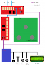
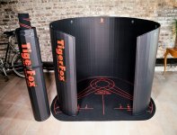
TigerFox Immerse 360 portable listening pod. The TigerFox Immerse 360 dramatically transforms the quality, immersion, and three-dimensional audio performance of even a standard pair of speakers.This new product is said to make people willfully throw awaytheir headphones! Free 5 minute trials on Saturday at event. Inventor Rick O'Polka of Milwaukee will be on hand for free demos and sales. $500. https://tigerfox360.com/technology

The following Manufacturer's Representatives will be present to answer questions. Phil Jackson of Parasound, Rick O'Polka of TigerFox, Jerry Willsie of Straightwire, Dennis Murphy reknowned Speaker designer of Philharmonic Audio, Jeff Dano of KLH.

For additional information please see AZAVCLUB.com.

Attachments

  • SpeakerFest.jpg
    SpeakerFest.jpg
    749.7 KB · Views: 202
  • TF_Front_Compare-scaled.jpeg
    TF_Front_Compare-scaled.jpeg
    554.7 KB · Views: 197
  • Like
Reactions: orchardaudio

LinearX LMS, Glitches in Frequency Response at 100, 1,000, and 10,000 Hz

Hello,

I'm posting here because this forum is one of the few places that the now-defunct LMS (Loudspeaker Measurement System) by LinearX has been mentioned.

I recently noticed glitches in the frequency response at 100, 1,000, and 10,000 Hz.

I ran the external analyzer calibration routine which reported no errors between the oscillator output and line input.

However, when I run a loopback measurement from the oscillator output to the line input, the glitches are visible.

I would greatly appreciate if anyone else has seen this problem and was able to fix it. Thank you very much in advance.

Attachments

WTB Peerless 1727 (831727)

I need to buy a pair of Peerless 1727 (831727) 10 inch woofers (see data sheet attached). They have been out of production for quite some time. I have a four piece system that uses a total of four of these drivers. Amp failure damaged two.

I know this is a long shot but I thought I would give it a try...

Attachments

LinearX Lms 4.x - Complete Software Setup.

Hello everybody.
I am looking for the complete software for LinearX Lms, version 4.6, alternatively also 4.1 or 4.0 or even all versions.
The update setup on the physical Lab site does not work for my version.
I currently have the Dos, Linearx Lms 3.5 version only.
Please, I ask you for support.

My email is:

martincastrovincisystems@gmail.com

Thanks for helping me.

FS: Quasimodo test-jig V4 PCB

Hello,

here I offer Quasiomodo v4 pcbs from Marc Johnson.
(Simple, no-math transformer snubber using Quasimodo test-jig)

costs 8€ each pcb

Shipping in padded envelope (not insured, not tracking) to
  • Germany (without islands): 2,50€
  • Shipping in EU: 4,50€
  • UK: 10€ as small parcel (because Brexit & new custom laws, not insured, not tracking)
  • other countries please ask

preview

Hybrid issues

Anyone can help!!

I bought two hybrid+ from generoso cozza.

I build the supply for the heating, and the time delay and the ps for the PowerMosfets myself and they work, when i switch on the hybrid+, the mosfets and the resistors in front are burning, I dont know how to adjust, and find out where the problem lies. The only thing Mr. Generoso tells to me is: "it must work".

I should say, that i have build several mos fet amps without problems.

Can anyone help me ?

Using Aluminum Organic Polymer Capacitors in DC Servo Power Supply

Hi All,

The current electrolytic capacitors in this DC servo power supply circuit seem to be running too hot around 85C. Will Aluminum Organic Polymer Capacitors run longer in this circuit by staying cooler?

https://www.mouser.com/datasheet/2/293/e_ucd-1795093.pdf
https://www.mouser.com/datasheet/2/420/PXGRA_e-2507364.pdf

The data sheets show the AOPCs have much lower ESR, much high ripple current rating, but they also have higher leakage current than the Aluminum Electrolytic Capacitors.
Does this necessarily mean they will run cooler in this application? How does a high leakage current play into things?

Attachments

  • Screen Shot 2022-05-24 at 6.37.05 PM.png
    Screen Shot 2022-05-24 at 6.37.05 PM.png
    38.4 KB · Views: 268

What happen to adjustable passive speakers?

Older speakers had adjustments that could be made on them. I discovered this after I looking at how cross-overs functioned and wonder why i was not seeing adjustable cross-overs. Then I happened appond a pair of at-12 speakers for cheap at an estate sale. Do these speakers and others like them have adjustable cross-overs?
Why are newer speakers designs not including such adjustments (I'm guessing it has to do with making them as cheap as possible)?

Comparing DIY LM3886 amps with commercially available amps

Hi,
I went to a local hifi shop in Bangkok to look for new speakers to match my DIY 3886. Some are quite interesting such as, Polk R200, Triangle BR03, some Wharfedales and Dali, ...

The things is, I found lots of commercially available LM3886 amps. The shop use Quad Vena II Play for demos, I notice slightly warm and slightly bassy on the Quad (and I felt my DIY amp is tighter in bass). The shop also offers Leak 130 and Cambridge Audio AXA35 which I believe that all use 3886, albeit, different configuration and implementation.

Anyone has objectively tested those amps? Or maybe subjectively demo them? What's your thought, some of them offer great value when think about feature set (I wish to add remote to my DIY!) in neat package. They certainly lack of customizability and fun though. No adding oversize power transformer here! The most expensive is Leak Stereo 130 which I think it uses a 200VA transformer.

Best,
AP

FS: WBT-0102 Ag /Cu NextGen RCA Plugs

FS: Used WBT-0102 Ag /Cu NextGen RCA Plugs

I have following sets of used WBT-0102 NextGen RCA Plugs for sale:

- WBT-0102 AG NextGen (Set of 4 + Torx key) EUR 100

- WBT-0102 Cu NexGen (Set of 4 + Torx key) EUR 70

- WBT 0102 Cu NextGen (Set of 4 + Torx key) EUR 70

I used desoldering gun to clean but some residual solder remain. Please review attached photos.

Shipping for Europe is 10 EUR. Other areas, please inquire.

I am getting ready to move and clearing my drawers.

Attachments

  • IMG_1334.jpg
    IMG_1334.jpg
    1,008.5 KB · Views: 217
  • IMG_1333 (1).jpg
    IMG_1333 (1).jpg
    1,013.8 KB · Views: 200
  • IMG_1336.jpg
    IMG_1336.jpg
    995.1 KB · Views: 215

New Amp Purchase

Hi,

i just posted my introduction in the Introduction forum and write I would discuss my ADCOM amp issue in the appropriate forum so I hope this is the correct one.

I am looking for advice on what to do with my ADCOM amp and if it is best to sell it then of the 3 amps I am considering what the thoughts are as to which one to buy.

My ADCOM 5800 is clipping when my NAD 7240 PE, being used as a preamp, is at 50% volume. I have not tried using the NAD as the amp by putting the jumpers back in so I do not know if it will clip with just the NAD.

However, I have been told the ADCOM amp is the issue & I need to immediately disconnect it before I blow the tweeters on my Maggies. The D-Sonic M3a-600M mono blocks for $2,375, the D-Sonic M3a-1200S Stereo for $2,075, or the Parasound A21+ for $3,500 are the amps under consideration.

I do believe the ADCOM is the issue because I moved in February 2021. I hired the contractor who had remodeled the house I sold to help move. Without asking me, he put the ADCOM, in the original box, on the back of his 16 foot trailer behind his big diesel truck, at an angle, and drove down the very rough dirt and gravel road. When I loudly complained he said he drove very slow. Lol sure. Anyway, the ADCOM has been on a shelf waiting for the Maggies to be finished. We did test the ADCOM on a less expensive set of speakers and they did ok. However, we did not play them at a louder volume and this is when I noticed the issue with the Maggies.

Thanks for the thoughts.


Here is a recap of my system:
---ADCOM 5800
---Pioneer PD-19 CD jukebox
---Onkyo CP-1038A turn table
---Marantz HEOS NA-6006 Network Music Player
---NAD 7240PE Receiver being used as a pre-amp
---Magnepan MG1.6/QR speakers purchased in December 1998, shipped them to Magnepan in February 2021 for a factory rebuild, Magnepan shipped them to Peter Gunn, and he did his modification to the speakers

Elekit TU-8500 question

Hi all

I am about to commence building my TU-8500. I have read in some reviews that people suggest to add a “step up” transformer when using the MC cartridge with the Phono stage. People that have built and have used this pre amp with a MC cartridge - What is your experience ? If people are using a step up transformer which brand/model are they using ??
Many thanks
Cheers
Bruce
Oz

For Sale Tubelab TSE-II bare board and numerous parts

For sale is a Tubelab TSE-II bare board and some parts, including the 10m45s ICs and the Microchip MIC29502WT regulator chip.

SOLD

You can pull up the BOM at this link:

https://www.diyaudio.com/community/threads/after-a-14-year-run-the-tse-must-die.331038/

I previously built a 300B amp, and have this board and parts surplus to my needs.

Included in sale:

TSE-II board,

Capacitors: C2,3,4,5,6,7,8,10,12,13
Supplemental Capacitor: 45uf 440VAC Motor run cap
Diodes: D1,4,5,6
ICs: IC 1,2,3
Q1 and 2 which are STF3LN80K5 mosfets

The six called out on board heatsinks.

All parts would work in a 300b build, some substitutions may be necessary for a 45 or 2a3 build.

IMG_0680.JPGIMG_0681.JPGIMG_0682.JPGIMG_0683.JPG

mechanical resonance in MMs

Slightly off the wall one here but been reading a very interesting article from the mists of linear audio volume 3 by Steven van Raalte and comparing with the Bob Cordell vinyltrak article. In it he discussed an inverse resonance filter for dealing with the resonances that MM manufacturers build in to prop up the high end response, the end result usually being a bump in the response somewhere between 12 and 15 KHz then a 4th order roll off. Whilst this is
not a horrendous problem for us oldies who can't hear up there anyway it is predicted that this causes some unwanted time domain issues that the inverse filter addresses.

Now what would be nice is for there to not be any resonances at all in the audio band. Low inductance cartridges don't need the help so don't have the resonance. Therefore there is something about the design of the cantilever and/or the suspension that causes this. Once we know what it is then we stand a fighting chance of working out how to remove it. If it can be addressed then, with some changes to cartridge loading as discussed by both Cordell and van Raalte we can get a nice 1st order roll off to well above 20KHz and put the MM back on a level footing with MC models. Looking at this more deeply it appears this issue is one of those that was well known about in 1975 and many have forgotten.

So first step is to get a grip on the potential problem. Now I have 3 cartridge types I am interested in (as in own)
1. AT 150MLx 2K 450mH, 100-200pF recommended load
2. Ortofon super OM 1K 580mH 200-500pF recommended load
3. A&R x77 series (aka Garrott, aka Sumiko Pearl, AKA shelter 201 etc). 580 580mH

The last one is more of a 'project' as I have 4 cartridge bodies to perform evil experiments on and there are a wide range of replacement stylus types that will fit including the sapphire Jico SAS.

Now immediately I have run into some problems as both the Cordell and van Raalte cartridge models are over simplistic. Digging into this further shows the model is more complex and difficult to measure (Elliot). So we need to get empirical. More research shows that the best way to do this is to find a test record with square waves on and measure the response. Bother I don't have one of those, so £40 will have to go Ortofon's way as willing to bet CBS STR-112 costs $$$ these days. Once I have Jan's permission will pop in a diagram from the van Raalte article to show how the inverse filter cleans up the ringing on square waves. If I am right (unlikely but we all get lucky sometime) then you can record the output of the preamp and use audacity to mess around to find centre frequency and Q for the filter. When that is known we can see how much of a resonance is designed in.

Note: I am expecting to find that the ortofon and AT are not using too much in the way of mechanical cheating, but suspect the A&R does. Certainly both ortofon and AT have -3dB points at 30kHz which suggests the main cantilever resonance is way out the audio band.

Links. There are a couple of JAES papers that would help in this, but at $33 each I'll bumble around being empirical a bit longer.
https://linearaudio.net/sites/linearaudio.net/files/lte_vol3_1.pdf
Magnetic Phono Pickup Cartridges
http://www.kallhovde.com/advent/phono-pre-research.pdf

Sound digital 12000.1D help

Hi guys. Have a sound digital 12000.1 here that I just would like to confirm I have the right ID on these parts before buying. Need a 15v smd diode. Is this just a regular diode or anything special?
My local online supplier don't seem to stock any regular 15v SM Diodes....
Photos below. Thanks

Attachments

  • 20220309_120747.jpg
    20220309_120747.jpg
    411.6 KB · Views: 126
  • 20220309_121121.jpg
    20220309_121121.jpg
    217.3 KB · Views: 127

Myyyyyyy GORILLA!!!

Greetings, MY GORILLA 2400 watt Class D amplifier has a bad transistor upon INITIAL exam. Transistor on the way tomorrow SO... check things out. It APPEARS I am not the FIRST to repair this near SPOTLESS amplifier. It is so shiny it dont even have any DUST on it. SUPER CLEAN. I examined the board and its obvious there is a REPLACEMENT transistor in there. WELL its on the SAME side as the DAMAGED transistor so I am ASSuming these transistors are not holding hands and merry... I will attempt a replacement of the bad transistor and hope for no other bad aspects BUT.... worried this thing will self destruct yet again upon HARD USE. Only way to tell is... HARD USE so thats in the horizon IF I can get this thing to operate again. Myyyyyyy GORILLA!!!!
Projects by fanatics, for fanatics
Get answers and advice for everyone wanting to learn the art of audio.
Join the Community
507,687
Members
7,884,287
Messages

Filter

Forum Statistics

Threads
406,040
Messages
7,884,287
Members
507,687
Latest member
sarah xenran