3FE25 UTP Cat 5 star quad - speaker cable
- By claudiogan
- Everything Else
- 0 Replies
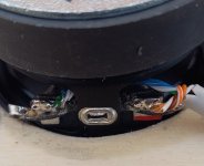
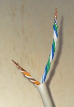
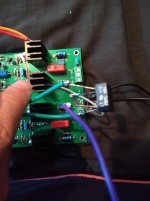
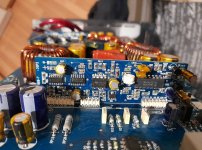
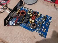
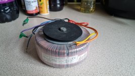
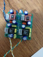
I changed the wiring of the MDD3ZC350 prototype using UTP category 5 network cable. The orange, orange-white, brown, brown-white wires are in parallel in the positive pole. In the negative pole the green, green-white, blue, blue-white wires are in parallel. The twisted pairs are diagonally in a star quad configuration.
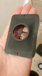
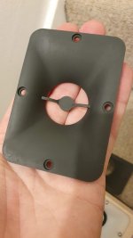
The positive pole wires are 25 mm shorter than the negative pole wires which pass behind the spoke of the 3FE25 driver's steel basket. Care must be taken to maintain at least one mm of distance between the spider and the negative pole which passes behind the spoke of the basket. Both poles are soldered directly onto the driver terminals and the couple of meters long lead goes directly to the amplifier with 4mm banana plugs.
Listening to it I noticed an improvement which however could be due to the elimination of the crack in the left channel flange. It is a simple wiring to make, very cheap and effective in minimizing electromagnetic disturbances, I will also use it in the next prototypes.
In recent years I have documented the optimal RLC parameters that the cable connecting the speakers should have. My conclusion is that since these are linear parameters they cannot degrade the quality of the reproduced sound. There are many simple and inexpensive techniques that reduce the three parameters to levels suitable for a home system. With capacitances and inductances that are too high, the frequency response is affected above all.
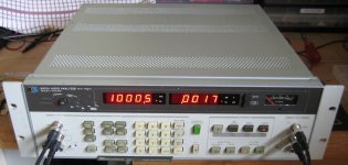
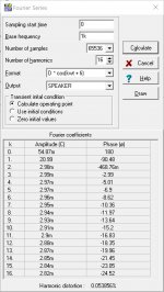
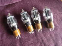
This wiring has a capacitance of approximately 100 pF/m and keeps the inductance at low levels (reduces the magnetic field emitted). The reduced section of the cables is not a limitation in this case, with the 3FE25 driver from Faital-Pro with one watt it exceeds 90 dB at one meter. Going further can disturb family members, neighbors and even your own ears as the driver starts generating distortion.
The main advantage of this wiring is the particular geometry which reduces the effect of electromagnetic interactions. In particular, it reduces the emissions of the cable itself which can generate non-linear phenomena by interacting with the driver and the amplifier. In star quad wiring, for each circuit that generates a magnetic field, there is a second that generates a magnetic field of opposite sign at a distance of a few millimetres. The elimination of the connectors avoids having surfaces of a few square centimeters capable of emitting magnetic fields. Passing the negative pole wire behind the spoke of the driver basket avoids inserting ferromagnetic material into the circuit.
Star quad cabling with a single UTP cat 5 cable can be used for powers up to about ten watts, with an impedance of 8 Ohm the electric current remains less than an ampere. The low capacitance makes it suitable even with low power amplifiers.
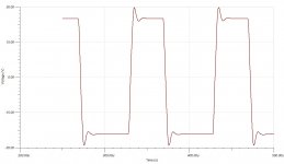
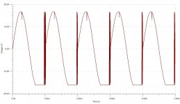
The proximity of conductors forming four circuits in opposite orientations reduces total inductance and minimizes interaction with ferromagnetic material in the vicinity of the speaker wire. Each ferromagnetic object greatly increases the magnetic field in the area in which it is located and also the magnetic flux chained in nearby circuits. The effect is more pronounced if ferromagnetic material is inside the circuit. In the case of the radius of the drive basket with the standard connection a non-linear component is created in the inductance of the circuit, when listening at low volume or in the car it does not create problems, if you listen to a flac song with a quality system you can perceive the distortion.
Thanks for your attention.
links:
https://www.claudiogandolfi.it
https://www.claudiogandolfi.it/662g.html
The positive pole wires are 25 mm shorter than the negative pole wires which pass behind the spoke of the 3FE25 driver's steel basket. Care must be taken to maintain at least one mm of distance between the spider and the negative pole which passes behind the spoke of the basket. Both poles are soldered directly onto the driver terminals and the couple of meters long lead goes directly to the amplifier with 4mm banana plugs.
Listening to it I noticed an improvement which however could be due to the elimination of the crack in the left channel flange. It is a simple wiring to make, very cheap and effective in minimizing electromagnetic disturbances, I will also use it in the next prototypes.
In recent years I have documented the optimal RLC parameters that the cable connecting the speakers should have. My conclusion is that since these are linear parameters they cannot degrade the quality of the reproduced sound. There are many simple and inexpensive techniques that reduce the three parameters to levels suitable for a home system. With capacitances and inductances that are too high, the frequency response is affected above all.
This wiring has a capacitance of approximately 100 pF/m and keeps the inductance at low levels (reduces the magnetic field emitted). The reduced section of the cables is not a limitation in this case, with the 3FE25 driver from Faital-Pro with one watt it exceeds 90 dB at one meter. Going further can disturb family members, neighbors and even your own ears as the driver starts generating distortion.
The main advantage of this wiring is the particular geometry which reduces the effect of electromagnetic interactions. In particular, it reduces the emissions of the cable itself which can generate non-linear phenomena by interacting with the driver and the amplifier. In star quad wiring, for each circuit that generates a magnetic field, there is a second that generates a magnetic field of opposite sign at a distance of a few millimetres. The elimination of the connectors avoids having surfaces of a few square centimeters capable of emitting magnetic fields. Passing the negative pole wire behind the spoke of the driver basket avoids inserting ferromagnetic material into the circuit.
Star quad cabling with a single UTP cat 5 cable can be used for powers up to about ten watts, with an impedance of 8 Ohm the electric current remains less than an ampere. The low capacitance makes it suitable even with low power amplifiers.
The proximity of conductors forming four circuits in opposite orientations reduces total inductance and minimizes interaction with ferromagnetic material in the vicinity of the speaker wire. Each ferromagnetic object greatly increases the magnetic field in the area in which it is located and also the magnetic flux chained in nearby circuits. The effect is more pronounced if ferromagnetic material is inside the circuit. In the case of the radius of the drive basket with the standard connection a non-linear component is created in the inductance of the circuit, when listening at low volume or in the car it does not create problems, if you listen to a flac song with a quality system you can perceive the distortion.
Thanks for your attention.
links:
https://www.claudiogandolfi.it
https://www.claudiogandolfi.it/662g.html