Maxon motors for TT use

Hi Folks,

Various people have asked about this so here is something I wrote for the maxon AU web site. It is by no means an exhaustive list, although the suggested model families are a good choice there are many variations within those families, primarily nominal voltage, which as explained below can prove critical in the selection process. Also $AUD one off prices are given in the pdf..they are for comparison only. Call maxon for an exact quote as the exchange rate varies. I do not claim to be the foremost expert on this topic, I respect others, such as Mark Kelly for one, have done much work on this.

Maxon Brushed motors for Hi-Fi turntables

Much has been written about this subject and I appreciate that others have gone into considerable detail. The purpose of this document is to put together suggested motor choices available from maxon in one place, and give an idea of the relative pricing. Note these are guide prices only as for example, the exchange rate fluctuates. Also note, we have ‘cherry picked’ some likely motors here, but this list is in no way exclusive. Other motors in these series and other series may be suitable. If you are not sure please call maxon.

Before we start we should outline the basic requirements

1) Sufficient power, ie speed x torque
2) Low noise, electrical and mechanical
3) Minimal torque ripple
4) Reasonable cost

For most people, particularly novices, a brushed motor is a good choice. The control electronics are comparatively simple and as they can be linear, low noise and the cost is lower. The wiring is also simpler, just two wires to the motor. The drive system is inherently smooth and quiet as long as we are aware of some basic points.

Motor Selection

For a retrofit situation we often have little control over the mechanics, the motor speed is much as determined by the original design. In the case of TT’s employing synchronous type motors this may be quite low, much less than 1000 rpm.

This requirement is usually at odds with the brushed motors available, which tend to be high revving when run at their design voltage, typically 4000 to 6000rpm.

Fortunately the solution is at hand. By using a large diameter motor (which provides good torque, and more power than is ever likely to be required) we can under run it from a lower voltage than its nominal design voltage. This will reduce the speed whilst torque remains purely proportional to the supply current. From a datasheet perspective this means selecting motors with a low rpm/volt speed constant, line 13 in the maxon data sheet tables.

Taking the A-max 26 110191 as an example, a nominal 48V motor, this has a speed constant of 127 rpm/V. So we can see that in a typical turntable application (~600rpm) the supply voltage will be only approximately 4-5V. This is perfectly fine as long as the motor has sufficient torque. From the datasheet the motor makes 15mNm torque at max current.

As the turntable belt drive multiplies the torque by 20X approximately this is quite substantial. We could go into more details as regards start up times if we know the moments of inertia, frictions etc etc, but unless we are designing for broadcasting applications this is probably not required here. In most real world situations belt slip will limit the torque in any case.

So we need to look at some large diameter brushed motors, large in this context is ~>25mm diameter, with low volt/rpm..

What else is important? We want the lowest noise, mechanical and electrical. This means minimal brush noise and low torque ripple. So the choice is now towards precious metal brushes (PMBs), for minimal drag, noise and best efficiency, a long life capacitor (CLL) module to prevent brush sparking and as many poles as possible for smooth torque delivery.

Some suggestions, in order of cost, lowest first.

A-max 26 series

A-max 26 7W 13 pole 110191 an old favourite and still a good choice

RE-max 29 series

RE-max 29 9W 13 pole 226779 (bit more power has extended shaft)
RE-max 29 15W 13 pole 226761 (more power for heavier platters, faster start etc)

The RE-max 29 and A-max 26 support both DC tacho (as a special) and encoder options.

RE 25 series

RE 25 10W 11 pole 118748 (with extended shaft, more power smaller size, tacho option)
Can have DC Tacho 118909 factory fitted for closed loop control

The RE 25 comes with the option of a factory fitted DC Tacho 118909, and so if required a true ‘closed loop’ control can be closed around the motor and the speed controller. It is also the most powerful motor for its diameter, which may help in some conversions, although it is also the longest. See table for approximate dimensions.

Speed control.

The LSC 30/2 4Q linear controller 250521 could be used for TTs. It supports I x R mode. This technique provides motor speed control by a form of feed forward. A brushed motor can be modelled as a source of voltage (the back EMF) in series with a resistance (the winding and brush resistance) . The voltage is proportion to the motor speed and opposes the supply voltage. The current is proportional to the motor torque. As motor torque and current increases, and the motor slows, the current increase is measured and used to estimate an increase in motor supply voltage in an attempt to stabilise the speed.

As there is no true feedback control, the accuracy of this arrangement is limited. The advantage is that no feedback device is required, so simple, low cost, and there is no NFB loop to stabilise.

The more accurate option is to use a motor with the Tacho option. Coupled with the LSC30/2 or other DC servo amplifier this would give absolute control of the motor speed. However be warned the combination of a high mass turntable, compliant drive belt system and low motor inertia will make the loop more difficult or impossible to compensate.

Further hints and tips

Check the drawing of the motors carefully in the datasheet to get the exact dimensions; those above are a guide only.

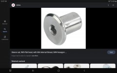
Be careful not to damage the motor when fitting the drive pulley. In particular the shaft of the motor must not be subject to excessive axial loads which might damage the bearings. If press fitting chose a motor with an extended ‘through’ shaft, then the press can be applied carefully directly to the shaft.

Never press on the motor body to press fit a pulley.

Details of all motors are on our web site:
www.maxonmotor.com.au

Attachments

Woofers- Tweeters and XO Parts BEST OFFER TAKES ALL

LOCATED 44405--- BEST OFFER TAKES IT ALL- Everything works....Over $2200 in drivers and $500 in XO parts... XO parts some have booger soldier as i dont have a removal tool. A couple woofers kids poked dust cap- yeah I know it makes no difference- but I wanted to be up front. Theres also 3 more XO "sets" has 3 more 2.o air coils 20uf caps 3ohm 7.5ohm resistors 1.8uf 4.7uf caps and 0.9/1.0 air coils. they are in cabs- hot glued in. I can include the cabs which are 3.

Must be picked up unless you have the means to send boxs/packing with return label im not paying sipping out of my pocket if that happens Venmo or something else. I don't use Paypal


Attachments

  • 20220407_183036 (1).jpg
    20220407_183036 (1).jpg
    296.5 KB · Views: 84

Alpine PDX M6 no output

Hello, i received a alpine pdx m6 sub amp.. Repaired the filter caps, because broken. Nothing more. Amp powers up, 1,08Amps idle.
Oscilation at output perfekt. Traced input signal from input preamp board to mainboard, also perfect... Must be something between drive ic and mainboard. Expect a broken resistor.
Cant find something. Anyone has a diagram, or had this failure before?

Troubleshooting 50 dB left right channel Crosstalk on Creek Audio Destiny Integrated Amplifier

Hi All,

The published specs are 60db so it doesn’t surprise me I’m still in the ballpark.

The analog source is a 1kHz sine wave from a DAC with one RCA plugged into the Aux input opposite of the channel being tested for crosstalk.

I used my DMM to measure AC voltage at the the amp speaker terminals, without speakers.
Measurements are as follows: 170mV vs 0.5mV. Crosstalk is 20*Log(V1/V2) = 50db. It’s a few db worse crosstalk from left to right. I’ve been able to double check my measurements using the amp headphone output connected to the input jack on my Mac, recording that input on Audacity and then running a FFT analysis. The 50 db crosstalk is consistent and gets worse as frequency increases, as expected.

Is the most likely cause capacitive coupling via the L/R channel wires (marked in red) that go from the Input board to the volume control and back? These wires, 3 per channel, converge to a 6 wire conductor with shielding, and a drain wire that is connected to ground. The cable length is about 2 feet. The signal then goes through the mute relay to a pair of wires (marked in yellow) that connect to the left and right Amp sections. I think the sequence is Input to Volume to Pre Out to Mute relay to Amp In. Running in Passive preamp mode. I’ve attached photos with and without the markings. See pages 2,8, and 9 of the attached schematics for reference.

I’m wondering if there is a way to improve the crosstalk? One idea is using a Cat7 ethernet cable which has shielded pairs, outer shielding and a drain wire. Or just running separate wires which would take more space. Or is there a lot more that is causing the crossover? And is troubleshooting 50db really worth the trouble? I should add one motivator to replace those wires is a bigger voltage spike (barely audible) in the right channel when changing inputs. Any help is appreciated. If anything, learning more about crosstalk sources would be great.

Attachments

  • 4A788F9A-78B0-4164-A670-91AD2922D34D.jpeg
    4A788F9A-78B0-4164-A670-91AD2922D34D.jpeg
    300.7 KB · Views: 323
  • hfe_creek_destiny_int_schematics_en.pdf
    hfe_creek_destiny_int_schematics_en.pdf
    3.1 MB · Views: 153
  • 786E382E-BC2D-4DB2-B8B0-5D90DB71CF5D.jpeg
    786E382E-BC2D-4DB2-B8B0-5D90DB71CF5D.jpeg
    111.2 KB · Views: 181
  • 2F2EB12A-B9C8-4D89-BE11-3CBBFC9D2668.jpeg
    2F2EB12A-B9C8-4D89-BE11-3CBBFC9D2668.jpeg
    300.8 KB · Views: 232

Fixing 2 QSC RMX1450's

Hi all, I am teaching myself soldering and how to fix my own amplifiers. I bought a pair of these QSC RMX 1450 VERY used off of facebook marketplace knowing the right channel in both did not work. (suspecting something someone did with bridging at some point in time). I knew these were rough, but they seemed like a good project to start learning on for the price.

When I bought the amps, the fuse for the right channel would blow instantly when powered on (12A) I tested the bridge rectifiers and they were failing so i replaced all 4 (2x on each amp) with the closest I could find to the original rectifier GBPC2502W-ND https://www.digikey.com/en/products...2?s=N4IgTCBcDaIOICEAKBhMBWADGA6gWgDkAREAXQF8g

After I replaced those, the fuse would still blow. then I tested the Bipolar Transistors (8 per amp channel, 16 total per amp) a few of them were failing the test on the bad channels, so I order 16 of them (I did not replace the other 16 on the good channels). 757-2SC5200-O(Q) https://www.mouser.com/ProductDetail/Toshiba/2SC5200-OQ?qs=EEns8I54Y6BCHV7Kwts0vw==&countryCode=US&currencyCode=USD

Success! I can turn the amp on and it no longer blows the fuse! however, after hooking a speaker up to the right channel I got a really loud humming noise coming out of it and then a cap started sizzling and the top popped off before I got the amp unplugged. I let the amp set for a couple days then just unsoldered the 4 caps off of the bad channel and am a little defeated, but again its a learning project and my first time doing something like this.

The question(s) Are:
1. what produces that humming sound I heard?
2. should I go ahead and replace ALL of the caps? (total of 16 caps between both channels on each amp)
3. if so is there anything else I should replace aswell?
4. should the 2 good channels have there 8 Bipolar Transistors replaced too?
5. what caps should I go with and why? I know theres got to be better ones out there since these were made.

Cap Specs: 100V, 3300uf, Nichicon, 25mm x 50mm. the new ones cannot be more than 25mm wide, but could be taller if need be.

I saw this post and thought it was interesting that I could go bigger https://www.diyaudio.com/community/threads/bulging-capacitors-on-qsc-mx1500.367169/post-6513907

Thank you for helping a beginner!

Beginner TL hornresp question - is driver very close to vent ok?

Hi,
request help - I am learning hornresp to design a TL for Tectonic TEBM65C20F-8 driver. My question is although the power level looks flat, the driver position is very close to the vent, it that ok or am I doing something wrong? Please find attached few screenshots from hornresp. Thanks for your help.

Attachments

  • driver-parameters.JPG
    driver-parameters.JPG
    21.9 KB · Views: 48
  • filling.JPG
    filling.JPG
    88.9 KB · Views: 48
  • power.JPG
    power.JPG
    102 KB · Views: 52
  • Schematic.JPG
    Schematic.JPG
    83.8 KB · Views: 52

Linkwitz LM4780 PCB Proposal: Comments Wanted!

After building a set of LM3886 amps based on the Linkwitz circuit (which I really like!), I figured I would try an amp using the LM4780 based on the same circuit layout. Since I haven't used this chip before, I figured I would ask:

1) If anyone has used the Linkwitz circuit ( http://www.linkwitzlab.com/images/graphics/3886amp.gif ) using the LM4780 as two LM3886's. I know other amps (Brian and Peter's come to the front of my mind) use this chip in a similar manner, but I was specifically interested to see if anyone has used the Linkwitz topology. It should be fine, but there is no since in re-inventing the wheel if there is someone who has already found out any issues. (Searching the forum didn’t show much, but I figured someone has to have done this!!!)

And 2) Attached is a proposed PCB that fell together rather nicely, but I figured I would run it past more experienced designers first. Particularly, I am concerned about the V+ section coming from the input pin header to C+ and the input signal traces running along the top right edge of the board. If anyone has any comments either way as to whether my concerns are justified, or if I am in good shape, I would appreciate the feedback. Any suggestions or comments about the rest of the board are welcomed as well!

Thanks!
David


As a side note, I started off trying to make this a single sided PCB. That idea got trashed rather quickly, but I was wondering if anyone has used a single sided LM4780 PCB?

Attachments

  • lm4780c.jpg
    lm4780c.jpg
    37.7 KB · Views: 1,180

Hi from MO

Hi,

I joined this forum because I am trying to restore an old Pioneer car CD player, and am unable to source lasers for a unit that old. I have been working on it off and on for a couple years, and have all portions working except the CD portion of the unit. I would like to find a way to insert audio from a bluetooth device and try to have the CD portion work close to original capacity (I don't expect full functionality). I found a post on here where some users talk about using a similar chipset to what I have and am looking for information on how to accomplish this restoration. I have collected as much manuals and datasheets on the cd player, mechanisms, and chips as I believe is available at this time.

Here is the forum post I found: https://www.diyaudio.com/community/threads/cxd1125q-and-cxd1135q-spdif-output-mod.317359/
It doesn't mention doing what I am wanting to do, just that some other people have a better idea of how these old cd players work.

Is there a section on here that would be appropriate to start a build thread on this project? Are there also some other posts I should read before starting such a project?

Hope to learn from your expertise!

WTB Looking for single Tannoy gold 10" with crossover

It doesn't have to be pretty since the orphan I have is not pretty either, but it has to work. I'm in US but have family in EU so if you are not keen on sending abroad that's alright. I know Brits are already convinced that stuff is being delivered by teleportation and any other method is going to destroy their valuable possessions and it's best that perspective buyer will show up with cash and flowers and chocolate for thier spouses but that's not happening ,sorry🙂

A question about analog-semiconductive tech development in the recent Decade.

Greetings everyone! I really want to learn some knowledges about the analog semiconductor. Unlike the CPU\GPU\SoC sector, nearly everyone talked about "X nm", transistor count and etc. Very few audio-circuit amateurs will say something about the key technologies that makes our chip OPAMPs or even new BJT transistors better.
So, I·m curious about what have changed the analog semis in the past ten years?
From OPAMPs to the low noise LDOs and even the discrete transistors, too many high performance new models has came out within the decade, and what are the tech trend behand them?

I only know something that was stated on the official website, say TI has a ”high voltage CMOS“ tech that makes my old daddy stuned😎 .
  • Like
Reactions: dliscomb

New Year Party BoomBox Ideas 2.1 tall all in one

Hello Friends

I want to surprise my Famali with a DIY boombox that we will use for the 31st dec new year party
Its going to be used outdoor in the garden and have a powerpoint so dont need to have it battery powered

The items that I have with me is chinese make 2.1 TPA 3251 100 watts x 2 8ohms bluetooth and 200 watts Subwoofer amplifier the specs say it has 2 chips TPA 3251 so decent power can be achived 49v AC adapter. I tried this amp on my 3 way speaker and its super was surprised at the cost and performance


In Drivers I have the following below
Peerless TC9FD12- 8 3.5" FR 8 drivers total
variety of Subwoofer drivers with me
Peerless Tymphany 830946 6-1/2" Paper Cone Woofer Speaker 4 Ohm. 4 nos
Peerless Tymphany 830667 8" Paper Cone SLS Subwoofer 4 nos
Tang Band W8-740P 8" Subwoofer 2 nos
Beyma 12BR70 2 nos
I am confused what config to make since I dont know how to simulate WinISD sealed or ported , downfiring or Horn etc

It need to be all in one box can be tall but not flat horizontal like soundbar Bass area can be broad below part I guess and top part having FullRange
Music is electronic EDM and POp rock we will be playing. Around 40-50 people will be present and we will dance in open garden. Not enclosed area.

I also have Hypex nCore streo amp 500 watts per channel if you feel we should not use chinese TPA amp but then it will be stereo and not 2.1 I think even f we get f3-50hz should be good? I will keep one ipad for music and headphone to 2 rca it will go to amp.

I have been using Bose S1 pro and marshall Woburn blutooth speakers and its not great. Getting to hire DJ on new year is pain since our farmhouse place is far away from town once a DJ confirmed and last moment dint turn up thank god i had bluetooth speaker at least we hadsomething to play music

I am confused what to do please help people

regards
anand shah
tigeranand at gmail dot com incase someone was to connect via email
whats app +919867199941


TPA3116D2 400W Best 5.1 Class D Amplifier Board

Hi Music Lovers, Today In This Article We Are Going To This Tpa3116d2 Class D Ic Based Six Channel 5.1 Class D Amplifier Board…From Roger Audios. In This Article, We Are Going To Read About This Board’s Input And Output Connection Details And Technical Specifications.

Class d amplifier board

Where Do We Use This 6-Channel Amplifier Board? We Are Using 6 Channel Amplifier 5.1 Amplifier Board Maximum Used For Our Assembled Home Theatre Systems And Amplifiers.
If We Assemble A Home Theatre Or Amplifier For A House We Mostly Use Class Ab Amplifier Boards.

To Compare The Class Ab Amplifier Board This Class D Amplifier Board Will Give You Very Good Audio Results And Clarity. In Today’s Market, Many Branded Home Theatres And Sound Bars Mostly Use Class D Amplifier Boards For Better Audio Results. So That’s Why Today I Am Reviewing This Class D Amplifier Board.

class d amplifier board
Top View Of The Board
class d amplifier board
Bottom View Of The Board
This Board Is Made With Original Four Tpa3116d2 Ic And High-Quality Pcb And Components. If You Want To Know More About This IC You Can Click Here To Read This Tpa3116d2 Datasheet. This Board Is Manufactured In Tamilnadu India. That Also Provides Service Support In The Future. And Also They Are Going To Make Class D 2.1 Boards, Stereo Boards, And High Wattage Amplifier Boards In The Coming Days As Well. I Will Write More Articles If They Release New Boards.

[IMG alt="class d amplifier board
"]https://i0.wp.com/easyamplifier.com/wp-content/uploads/2022/12/image3-1024x512.jpg?resize=768,384&ssl=1[/IMG]
This Board Comes With Tpa3116d2 Four Ic ( I Have Already Mentioned That) And This Board Works With Single Supply DC (From 12v To A Maximum Of 24v. Recommended Supply Voltage Range Is 24v DC) This Board Comes With Two Stereo ICs And Two BTL Mono ICs. Two Stereo Ic For Front Left Right And Surround Left, Right. Two Mono Ic For Centre And Subwoofer Channel Output.

The Stereo Ic Can Give You A Maximum Of 50w Power Output Per Channel With A 4-Ohm Speaker. And You Can Get 35 To 40 Watts Of Power Output Per Channel When You Are Using An 8 Ohms Speaker. And The Center And Subwoofer Section You Can Get A Maximum Of 100 Watts Of Audio Power Output Per Channel Only If You Are Using A 2 Ohms Speaker. Otherwise, You Will Get Only 70 To 75 Watts Of Power Output If You Use A 4 Or 8-Ohms Speaker.


When Compared To Class Ab Amplifiers This Class D Amplifier Board Comes With Many Protection Features Like Amplifier Will Be Shut Down When Its Input Current Overload. And When The Speaker Terminal Is Shorted Or The Speaker Burn This Class D Amplifier Board Will Go To The Protection Mode. This Amplifier Will Go To Protection Mode When You Give Overload Input Gain.

Input And Output Connection Details Of This TPA2116D2 Class D Amplifier Board​

image1.jpg

All Input And Output Connection Details Are Clearly Mentioned In The PCB… If You Have Any Doubts About Regarding Connections You Can Ask Me In The Comment Section. This Board Will Run With A Single Supply DC. For Best Results, You Should Give SMPS Power Supply Range From 15v To 20v With 15 To 20 Ampere. Because This Board Ic Watts Total Of 400 Watts…

If You Want To Get Maximum Capacity Front This IC You Should Use A 20v 20 Ampere Power Supply With Proper 4 Ohms Speaker For The Front And Surround Channel And 2 Ohms Speaker For Subwoofer And Center Channel. So That’s All Friends. If You Have Any Questions Regarding This Board You Can Ask Me In The Comment Section Below… Bye Friends

Technics SU-V9

I bought second hand this amp and I would like to make a new glass door for it. Preowner made some plastic one which is very bad made and look terrible out.
Can anyone share originall dimensions and thicknes and where exactly the holes should be. It was originaly tempered glass used or just regular one with trimmed edges? I think it was not even completely clear but a little darker.

Thanks!

WTB Fountek FR59EXE

I’ve been looking on flea bay periodically and have a similar thread on diyma. These drivers have always been on the back burner to order but I never did and now they’re extinct, snooze you loose. I just want them in my collection of raw drivers to play with and maybe use in a build eventually. A simple search of 420Tabbycat on diyma will show that I’m a long term and active member if someone has a pair and wants to see if I’m ok to deal with. I’m not willing to break the bread on the Audible Physics ram2’s.

Impressed with the Peerless TC9FD18-08

I had my reservations with this TC9FD18-08 driver or other FR drivers, for that matter.

I tried that Nola clone, haphazard as it is, based on what seems to be several interpretations of the design.

Well heck, these little drivers in that situation sound quite nice indeed. Electric violin? Holy crap, man. Talk about riveting and real sounding. I have had them on for 4 days now and I have to force myself away from them and make myself go to bed. I'm no audiophile, but I have a rather nice collection of all different types of speakers.

Anyway, I am intrigued now. I want to try other designs.

I have a pair of Dayton PA130-8 that I don't remember buying, or why, and a pair of Mark Audio 10.3.

I did start a thread asking about the MA drivers and got some info there and reckon I need to purchase some plans for those (info needed as to how to go about that).

But what about these Dayton PA speakers? I have seen the thread about the .53x Karlson but those threads go for a lot of pages and I was not exactly sure which drawing went to what without starting over in that thread.

What I have for amplification is, a Denon 3805 with a separate DSP amp for my 12" subwoofer. Some amp boards (TDA8932) that I got for something else, a monoprice 50w hybrid and some old integrated amps (HK and pioneer) and another 2 channel board with a fan on it made by Sure, IIRC.

What could I expect from the PA130's compared to the Peerless TC9FD18-08? Would any of these amp boards work with these FR builds? If so, what to use specifically for a power supply? I read about laptop power supplies but they come in a variety of power ratings.

The Karlson types look interesting. Would 17-18 mm plywood work for that?

Any help would be appreciated.

volume control problem

I've got a Trends TA-10.2 integrated amplifier. The volume potentiometer wore out and I tried to replace it. In the process of desoldering it I damaged that part of the circuitboard so that it's not possible for a new volume potentiometer to work properly. The amplifier comes with a jumper system so that the volume control can be bypassed, which I tested and it works fine as a power amp (always at maximum volume level). I have two questions: 1. Is it better to install a gain control at the input, or a volume control at the output? 2. How would you go about installing it?

Zen Quad 22

Hi folks!

To complement my pair of Quad IIs (currently being restored), I decided to build a stripped down version of a Quad 22 pre-amp - what better design to partner the IIs? I know some mock the 22s sound, but I've always respected Peter Walker's designs, and - for nostalgia reasons more than anything else - I wish to build one for my Quad IIs.

This is a totally ground up design - I don't own a Quad 22 and won't shell out for one on Ebay as the prices are insane.

As mentioned, this will be a 'Zen' Quad 22 - I don't need the complicated switch-bank, or any of the balance/filter/tone controls. As most all of my sources provide 2V output I believe I am correct in thinking I can dispense with the EF86 stage of the circuit as well and have the sources go directly to the 500K volume control? (Got a nice stepped attenuator from China for this). The EF86 stage is present in the attached diagram, but I shall probably remove it for the next revision. Actually if you follow the original circuit diagram you can see that the Radio 2 bypasses the EF86 stage also and runs direct into the 500K pot.

As my Quad IIs use their original circuit values (apart from the dual section cap uprated to 2 x 32uF) I want to do the same with the 22 - no 'improvements', just stock values.

The problem I have at present - not being an expert in these matters - is how to imlement the required feedback to this circuit so it meets the Quad 22s original design? I know its feedback was part of the balance control section, but I have dispensed with this. Could some kind soul possibly draw onto the attached diagram the correct way to implement the required feedback?

The original diagram maybe found here: http://www.dc-daylight.ltd.uk/Valve-Audio-Interest/Schematics/QUAD-22-Schematic.pdf

Thanks so much!

- John

Attachments

  • quad 22r.jpg
    quad 22r.jpg
    82.8 KB · Views: 352

Replica Pre QUAD 22 - Questions on mids

Hi,

I just replicated a simplified circuit of preamp 22 of Quad, added a PSU and used on the audio signal path caps of 4.4uf (instead of only 2.2 uf) and of 0.47 uf. The pre seems to lack of mids. Modifiying the value of 0.47 uf to a lesser value would increase mid presentation? the 2.2uf cap, has any effect on mids? are there any other mods or changes to improve mid´s definition?
Thank you for your time and consideration. Sebastian

For Sale Vintage Telefunken 12AX7/ECC83 Tube

(1) Used & tested Telefunken 12AX7/ECC83 tube, made in West Germany. Both sections test strong on my TV-7 D/U tester; section 1: 60, section 2: 62 (min: 32). It also checks good for shorts and gas. The tube number is worn but readable. An embossed Telefunken diamond is on the bottom.

$35 via PayPal. First Class continental USA shipping is included.

Attachments

  • Tele_12AX7A.jpg
    Tele_12AX7A.jpg
    185.6 KB · Views: 90

PCB Source

Hello, I am located in the US.

I found this old magazine from 1979 that has series of articles with regards how to build a modular integrated amplifier. I would like to build the unit. The problem is that all the PCB's are picture-based (see example below).

The question is: Is there anyone who could take the pictures and fabricate the PCB's given that I provide all size measurements, of course?

Thanks in advance.

Best

Capture.JPG

Which caps to bypass power supply caps

Apologies if this is posted in the wrong thread. I have a couple Decware Torii amps. One mod offered by Decware is bypassing the power supply caps. There’s either four or six 33uf 450v caps. My question is what value bypass caps? Will 1.0uf 250v caps work? These are what I have on hand. I figured I’d see if these will work before having to buy others.

DIY speaker using high quality JBL speaker

Hi,

I cant afford buying a device like JBL BOOMBOX (it's a bluetooth speaker) but I found the speaker (the one that provides strong bass) and tweeter very cheap online (I paid 20 dolars) of this exactly same device (JBL BOOMBOX - it has 2 speakers and 2 tweeters). Picture below of the JBL BOOMBOX and of the speaker I bought:

aaa.png
bbb.png


The speaker is 4 inch, 4 Ohms and 30W RMS. It arrived today (it's original), so I connected it to my amplifier (which can drive much bigger speakers) but the sound does not look loud, it is actually very low (I even used a 10uF capacitor to filter mid/highs but the sound is not strong). I know I should put this speaker inside some type of wood box to make sound better and louder but I have no idea which size the box should be, if it should be sealed or if I should make a hole to allow air to to in and out. I know the JBL has radiators but despite being all plastic, they are very expensive (I have no idea why). There are plenty of speaker (like home theater speakers) that dont use radiators and have strong bass and loud sound.

So any idea the dimensions of the box that I should try? And what about the capacitor? Do you think 10uF is too much? The tweeter still didnt arrive, but for now I would like to try making the speaker sound better.

I know the JBL BOOMBOX has 2 speakers and 2 tweeters, but I still think the sound is very low... any idea how I can improve this? Do you really think using a wood box would help a lot?

Eden WT 550 Traveler, noise... and noise

Dear specialists,

A local bass player has asked me to look at his Eden WT 550 Traveler. It is a bass amplifier, with solid-state output, and a hybrid preamp (tube and solid-state). I'm in Switzerland so the wall power is 50Hz (230V).

I think the amplifier has (at least) 3 issues :
  1. 100Hz hum
  2. very microphonic tube
  3. remaining hum, constant level
  4. noise (is it white noise ?) with random "cracklings"
I cured the most apparent issue (1), the 100 Hz hum, by replacing the PSU capacitors. And then (2), I replaced the preamp tube (12AX7 of unknown origin and age), which was very microphonic. That issue is gone as well.

I will detail the 2 remaining issues. All measures done without any signal on input and with speaker on output.

3. remaining hum

First, I disconnected the preamp, and I was left with only issue 3 (remaining hum, constant level). The DC level on the speaker output is about 3mV, which looks ok to me, I didn't bother to adjust anything.

The remaining hum frequency is difficult to identify, even on the scope. Maybe 50Hz, or 100/ or even 150Hz. Here is a scope shot connected to the output :

file_1_output.png


The P2P amplitude is about 30-40mV. What annoys me are the spike around the crossing. Maybe that's what I hear. At least it looks ugly. Looking at a spike detail :

file_2_output_spikes.png


I tried recording this noise with my smartphone, attached as file_3_output_sound.zip.

4. noise (is it white noise ?) with random "cracklings"

This issue is the most annoying, its level is too high to be ignored, and the bass player asked me to try to get rid of this. Looking at the crazy cascade of components of the preamp, I'm not surprised it's noisy, but still let's try to silent it. Here is an attempt to scope it :

file_4_output_noise.png


I tried recording the noise and cracklings with my smartphone, attached as file_5_output_sound_noise_crackling.zip
The cracklings aren't the most disturbing and seem to be caused by the tube (removing the tube removes the cracklings). What is disturbing is the noise.

The schematics are attached as well. Do not ask me what version I have, there are notes all over the place and this amp has seen other hands before me.

Edit: reading this page made me wonder if this is worth the effort but let's try 🙂

It would be cool if you guys with decades of experience would be able to assist me.
Kind regards,
Charles

Attachments

Opinions on Pairing Satori MW19PNW-8/AMTPRO-4?

Hey There!
I just purchased a couple of AMTPRO-4s on sale from Parts Express and I'm looking for drivers to pair them with. My thought is a two-way with the Satori MW19PNW to keep it simple. Crossover would be an LR2@1500hz on both the low pass and hi pass.


Would this be a good pairing? Is 1500hz too low? Too high? The MW19PNW dips about 2db around 1200hz. Does that rule out this pair? Or, would I need a different x-over point, or can I work with the dip electrically to smooth it out?


Thanks in advance

Attachments

  • FR_Satori MW19PNW-8.jpg
    FR_Satori MW19PNW-8.jpg
    63.6 KB · Views: 763

Anyone recognise this Class-A project? - Recent Purchase

Hi all - I recently purchased a couple of mono class A SE solid state amps that were someone's old project, seemingly from an estate sale via an electronics dealer..


I thought this might be the best place to try and find any info on their design and if anyone recognises them from a thread on here..

There is reported some problems with them with the error light coming on and an impedance light coming on - I'm hoping the guy selling just didnt use them correctly, maybe over loading the inputs if these are for older, quieter line levels... I'll find out. According to the previous owner's family, they were in use with some large speakers in the past.

Photos attached.

Attachments

  • s-l1600[1].jpg
    s-l1600[1].jpg
    225.2 KB · Views: 144
  • s-l1600[1].jpg
    s-l1600[1].jpg
    314.4 KB · Views: 138
  • s-l1600[1].jpg
    s-l1600[1].jpg
    340.2 KB · Views: 145

For Sale 4 x ICEpower 50ASX2

Hi,

ICEpower modules are made by B & O (Bang & Olufsen in Denmark). They are essentially a complete power supply (SMPS), two D-Class amplifiers and and AUX power supply source all on one module.
FENDER did use them in their RUMBLE Bass amps for a while - I have attempted repair on one of them but got stuck on proprietary ICE chips.

So - repair is not easy - hence if any of you two in that thread are still looking for ICEpower 50ASX2 modules - I have 4 spares (surplus to requirements) if you're still interested. They are SE versions but can very simply be altered to BTL version.

3d printed tube sockets?

Hi,

Im fast running out of scavanged sockets and was wondering if 3D printed sockets coud work.

Ive seen this old thing from hackaday: https://hackaday.com/2013/01/15/3d-printing-vacuum-tube-sockets/ but that didnt really answer anything. You can 3D print basically any shape but if it will actiually work or not is an entirely different matter.

Looked around and i do have a lot of spring loaded pins that fit very well on the legs of a B9A or B7G socket tube i could use for the electrical connection but the heat from the tubes has me slightly concerned. PLA softens at 60C already, i could do PETG or ABS though but im not sure they would really hold up either. The glass is the main part that gets hot so i wouldnt be too concerned for something like an EL34 which has an actual base but these small tubes that have the glass right on the socket im not so sure.

Basically, has it been done with sucess before? If so can anyone link some models and what material was used?

Any IRS2092s repair gurus here?

I have aquired a few commercial pa speakers that use the 2092s chip and IRFB4227 FETS to drive the woofers. Looks like a mix of iraud7 and 9. Of the 5 speakers 3 would not turn on and 2 where extremely distorted. Of the 3 I have looked at so far 2 have had shorted fets and one that would turn on would not start oscillation. After removing the fets and the 2092 the power supplies all started and looked fine. after replacing the fets and 2092 on one of the modules it was found that the high side was not working and the low side would oscillate a few times then shut down at about a 350hz interval. These 350hz pulses where enough to pump up the the high side suplly well over 100v. I think this is what ultimately cuased the failures. Not sure if the 2092 went first or the fets? I looked at Voltage on VB and noticed the voltage collapsing. Turns out the bootstrap cap was bad. No suprise as it sits 1mm from the output inductor. So i replaced the 4.7uf electrolytic and the amp seemed to work fine. I thought, well i should replace the elecrolytic with a ceramic cap on the undeside of the board. (The previous owner has sent all the speakers back at least 2 times each for warantee repair .) I wanted a better solution than just replacing the cap to have it fail in 3 months. I only had a 10uf XR5 cap so I put it in. I figured the bigger cap should not cuase a problem exept maybe interfere with the pop supression a bit. I guess I was wrong it fried the 2092 chip immediately. This is the second chip i fried trying to fix these. The first was my fualt when i shorted Vss to Vref with a prob. It also took out the 4227's too🙁

Was I wrong in thinking a ceramic cap would be a good replacement? What mechanism woud cuase the 2092 chip to die from the bigger value cap? I built an amp with the dip version about 12 years ago and dont remeber them being so touchy.

TIA for any help.

Vintage V-FET Amps - Why So Little Interest These Days?

I've been wondering this for quite a while now and I'm hoping someone can help me with an answer. Why is there such little interest these days in these amps? I have a Yamaha B-2 and I'm always amazed at how wonderful it sounds; such depth and detail in the sonics.

V-FET's make so much sense as audio amplifying devices and except for Nelson Pass no one else seems to be too interested in them. Can anybody tell me why that is please?. :scratch2:

Two Matched pairs of 2SK180D

Quad matched 2SK180D, pictures and curves.
400 euros.
Also I have quad matched THF51S and 18 more, not matched but tried and with very linear curves.
Send a PM
Thanks in advance
Esteban Bikic

Attachments

  • Like
Reactions: Rodeodave

Output Transformer Proximity... Can they be too close together?

I'm just about to dive in on an EL34 push-pull amplifier build and am curious to know if the left and right output transformers (OTs) can be TOO close together. I found a schematic and notes in an MJ magazine I picked up in Japan and it specified a chassis size that is unavailable. I've got something close, but in order to get the OTs far enough away from the power transformer (PT) I've drawn them up as being about 5mm apart. Does the forum see any issue with this? Cross talk etc.?

Also, in this position do they seem far enough away from the PT?

I've attached a drawing of what I'm planning with relevant dimensions.

Thanks in advance!

Screen Shot 2022-11-30 at 7.11.37 PM.png

Amplifier selector

I'm not sure where to post this as I think it's one of a kind. Let me know or move it where it should be posted.
I've searched for a while and could not find a selector that lets one set of speakers and one line level input source, (pre-amp...ect) be the source for, as this one was built, up to "4" two channel amplifiers. I built it so I could hear differences between two channel amplifiers that I've built without having to connect and disconnect them every time. It's straight forward and easy to build. I jump connections across the negative speaker terminals. I used the 5v selection from the line level control board to feed and control the speaker board. Again I jumped the 5v input of the speaker board to select two at a time instead of one. Please Modify to your liking.
Hear is a list of materials.
Scott

HiLetgo 5V 8 Channel Relay Module with OPTO-Isolated Support High and Low Level Trigger​

DIY Switching Board 4 Way Signal Selector Amplifier Relay Audio Input Switch Module​

Banana Plugs for Speaker Wire (6 Pairs, 12 Pieces), 4mm Pin Plug Screw Type, 24K Gold Plated Connectors Insulated (Support 12 AWG to 20 AWG Wires) Two sets...​

RCA M/M Stereo Audio Cable... As many as you need.​

MEAN WELL RS-15-5 AC to DC Power Supply Single Output, 5V 3 Amp 15W​

HiFi DIY Audio amp chassis / table top enclosure / Instrument Case 20-12123N from Pi Metal Products Inc.

Other items are stand-offs, screws...ect.
1.JPG
1.JPG3.JPG4.JPG5.JPG6.JPG7.JPG9.JPG8.JPG7.JPG6.JPG

1.JPG

Attachments

  • 2.JPG
    2.JPG
    828.3 KB · Views: 219

Behringer Ultra-Dyne 9024, new..

Behringer Ultra-Dyne 9024, new..

"Vintage" stereo studio processor, new, never used, in original packing. Interesting component, from processing to sound equalizing/ analyzing. Also convertible to 8024 with cheap and simple Eprom exchange.

https://www.enjoythemusic.com/magazine/equipment/0101/behringer8024.htm


As said, really NOS, new, packed, never used.

Price 100€ plus shipping. (22€ EU Countries..)

Regards
b1.JPG
b2.JPG

PA guitar amp conversion - could use some insight on mystery tube amp

I’ve been looking for a PA amp to convert into a 1x12 combo guitar cab for a couple of months now, and finally found what appears to be an ideal candidate for a conversion.

70E738CA-ADB5-4B20-856F-77974695E04E.jpeg


This amp was made by Viking of Minneapolis, and the model number is PA-93.
The specs: 12AX7+12AU7 preamp tubes, 12AX7 PI, push-pull EL84 output. Actual wattage is unknown, since I can’t find a single mention of this amp anywhere, except for a brief video on YouTube that wasn’t very informative. Viking of Minneapolis was well-known for their reel-to-reel decks, but apparently not their tube amps. The PT and OT are beefy, but small, so I’m expecting this to likely be in the 13 watt range.

The controls on the front appear to be a rotary on/off switch on the left, tone, then two volume controls for the 1/4” mic input on the front and the rear phono input. The pot all the way to the left appears to be a bias adjustment of some kind. Maybe hum cancellation?

Here’s the gut shot.
15438C32-7979-4C14-8078-ECD74BC094E9.jpeg

All the date codes point to a manufacturing year of 1960. The latest code I’ve seen is the 36th week, on that cap just to the right of center. It has diode rectification, though I haven’t been able to identify those either. The diodes have “IR” on one side with a diode symbol in between, and the other side says “66” and right below it says “4241.”

Here’s some other close up shots of the interior.

12AX7 input:
741C5863-D00E-49EF-9EA2-B66021276FB9.jpeg


12AU7 second stage:

95FAB5B1-7F7A-4127-B75A-34A77EC6E6F8.jpeg


12AX7 PI:

CD4F5CCC-16AE-477A-9E2E-89D1FB4F7656.jpeg


EL84 power tubes:

BD4BE16F-127E-4041-ADC5-7D0FDE317C98.jpeg


The blue wire coming off the 8ohm OT tap here appears to be negative feedback of some kind. It connects to the resistor on the terminal strip and then back to the 12AU7. The OT has 70V, 8 ohm and 4 ohm taps:

0C7FB6AA-1878-47C7-A67A-6B4C01F667A3.jpeg


The kinda cool part is this came complete with tubes of unknown origin, and they ended up being a Telefunken 12AX7 on the input, and a pair of Mullard rX1 B0K EL84 power tubes, complete with soot. The other two tubes were just an RCA and a Sylvania, nothing special:

312ABA9D-993C-415C-B7D4-B42D545A59EE.jpeg


I’m not sure what state they’re in, since I don’t have a tube tester, but needless to say I’m buying replacement tubes to use while testing the circuitry, lol. Preliminary checks so far are very promising. The resistors haven’t drifted out of spec on all that I’ve measured, and even the caps all test good, which was the biggest surprise so far. We’ll have to see what happens when they get a few hundred volts through them.

I’ll probably end up having to trace out a schematic myself, but I was hoping somebody might know something more about Viking of Minneapolis, or about any other amp that used this circuit, that might point me in the right direction. Some of these old manufacturers are really tough to find info on.

Thanks!

Question on frequency vs age vs design.

Lets assume Im the only guy who will ever listen to this system.
Or lets say its just me and my buddies who are all in the same age group i.e. 55-70
Ive been reading up on how the human ear changes with age and so decided to do some tests. We found that all the people over the age off 55 could not hear anything over 14,000 Hz. Where as the kids and grand kids had no problem hearing even 18,000 Hz. Or more.
Samsung have this tech in their phones called Adapt sound. Where it plays a series of tones and based on your age and what your ears can pickup it creates a profile. The profile boosts all points past the point you can hear. The music does sound better. But if you do a freq test. You still cant hear the freqs past a certain point.
My quandry is
a. Do I build my system to just ignore all freq past 14K because thats all me and my buddies can hear.
or
b. Do I build a system that works like adapt sound which boosts freq above 14K
I know its a kinda pointless question. Which is why Ive stuck it in the everything else forum. But would still like you inputs.

Repurposing Hypex FA123 components

Background

I have a pair of FA123s that I no longer use. One of them has an issue I can have Hypex address, but I have another thought.

I'd like to repurpose the components of the FA123s in support of extending my home theater audio system (see attached image).

I have two stereo NCore amps that I use with a miniDSP device to integrate DML panels and woofers that serve as left and right front speakers.
I have additionally turned my LG OLED TV into a center channel speaker by attaching an exciter to it.
I have smaller DML speakers to serve as rear left & right channel speakers.

I have an A/V pre-processor that has the capacity to do the room equalization I may need.

I need amplifiers for the smaller DML rear left & right speakers and the center channel speaker.

I can use the working FA123 for the center channel, but this seems too much of a device for the purpose.
Additionally, as I would use RCA analogue out from the A/V pre-processor to the FA123, the FA123 would first do an ADC (analogue to digital conversion) make the digital available for DSP, then apply its DAC to return analogue output to the center channel speaker.

The FA123 does much more than I need.

This said, the FA123s's NCore amps - on their own - could prove a great match for my application.

Question

Could I repurpose any of the components of these FA123s?

I could have all the following wrong (see attached image) ...
The 100w amp appears to sit on a discreet board and receives power from the power supply mounted on the board holding the two 125w amps.
I don't need the DSP | DAC functionality.

Would the following work for the center channel amp?
  • RCA analogue inputs.
  • Binding posts for speaker wire.
  • Add an appropriate power supply for the 100w amp.
  • Supply mains connection.
  • Put in in a box.
The question then becomes whether I can do something similar for the rear right & left channel, but using the 125w amps and bypassing DSP | DAC.

I know I can purchase 2 or there UcD180HG with HxR from Hypex and put something together, but I really don't need 180 watts per channel.

These FA123s have served me very well across a number of different systems, I'd love to give them another life.

Any thoughts appreciated.

Attachments

  • Screenshot 2022-11-27 at 1.17.10 PM.png
    Screenshot 2022-11-27 at 1.17.10 PM.png
    1.4 MB · Views: 157
  • Screenshot 2022-12-01 at 4.44.32 PM.png
    Screenshot 2022-12-01 at 4.44.32 PM.png
    359.5 KB · Views: 162
  • Screenshot 2022-11-30 at 10.24.49 AM.png
    Screenshot 2022-11-30 at 10.24.49 AM.png
    1.6 MB · Views: 145

"ESSentielle" MHP DIY Speakers ESS Heil AMT3 / Satori Egyptian papyrus

Hi amigos,

Let me introduce my new DIY floor speakers (2.5 way) based on the "ESSentielle ADS" diagram of "la maison du haut parleur" (MHP)
The cabinetmaking is made of French Ash wood with a vertical grain. (25mm) cabinet size 100x28x30CM
These speakers are based on the famous ESS Heil AMT 3 Tweeter (latest generation) and two Satori MW16PNW-8 Woofers in Egyptian Papyrus whose measurements are here:

http://www.loudspeakerdatabase.com/SB/MW16P#8Ω

The Crossover has been the subject of a 2 year R&D with a gain adjustment, it is manufactured by the "Maison du Haut Parleur" in Toulouse, still in France. It has been specially developed to get the best out of the ESS Heil AMT3 Tweeter.
This Crossover is mounted with discrete SMD type components. The Woofer part is filtered at 6DB / octave with two Jantzen Selfs (Grade 1B copper wire @ 3% / 0.10 Ω) with a very low DCR.
Here are the cutoff frequencies:

385HZ/1700HZ.

Bass Woofer can go down to 32HZ @ +-3DB
I wouldn't be very objective if I gave my opinion, would I?))) But I'm in love with Heil AMT3 Tweeters and I must admit that the first time I listened to these speakers, I took a real slap!
The Satori Woofers seem to marry very well with the ESS Tweeter, the listening is musical, detailed and of a beautiful straightness.

For ESS fans : you can listen to the DIY kit in Paris / Toulouse and in Lyon if you are ever passing through) They are available in a version with a different cabinetry and less elegant than my DIY version but listening and electronics remain the same.

Here the review of the Heil ESS AMT3 Tweeters :

https://www.tnt-audio.com/casse/ess_amt_e.html

And here are the pictures 🙂


  • Thank You
Reactions: GM

  • Locked
New IRS rules for Paypal, Etsy, Venmo (etc) vendors and gig workers

The IRS has just issued a rule which will require companies like Paypal to issue a 1099K if your gross sales in any calendar year exceed $600. Previously a $20,000 PLUS more than 200 transactions was the threshold.

This even means if you have a garage sale, sell at a hamfest, or via your webstore the receipts will be recorded as "income" and you will probably have to file a1040 Schedule C (or some such).

Keep good records of your expenses!

Question on tube substitution

I've become enamored of dual-dissimilar triodes recently; spud amps just seem like fun to me. I've built a 6T9 and ECL82 and ECL86 amps.

I recently saw a nice-looking schematic for a 6CY7, a Novar base tube intended for television use originally.

6CY7 Single-Ended Hi-Fi Stereo Amplifier

I happen to have some NOS 6FY7, which are compactron tubes intended for the same purpose as the 6CY7. I looked at the tube data sheets and they don't seem to be very different from each other.

http://www.nj7p.org/Tubes/PDFs/Frank/093-GE/6CY7.pdf

http://www.nj7p.org/Tubes/PDFs/Frank/123-GE/6FY7.pdf

The main difference seems to be the plate dissipation for the output segment:

6CY7: 5.5 watts
6FY7: 7.0 watts

So other than the possibility of more output power, I don't seem to see much different. But I am a newbie. Am I missing something important here?

Thanks!

Mcintosh MAC 4100 bias adjust

I have a MAC 4100 that I am trying to adjust bias on. I read the SM instructions for the procedure but would like to know precisely where I should be clipping my meter leads to to read the AC line current. I tried to read across the fuse holder with the fuse installed, but that only read 7 mA on my Fluke meter. Without the fuse installed the speaker relay would not energize. Mcintosh experts help would be greatly appreciated.

Recapping/modding yamaha m916 console HELP

Recently got an m916 which im using for tracking to a tascam trs-8 and summing. planning on recapping at least 8 channels and the master channel. Been reading through a groupdiy forum of a recap on the same board but all of the schematics with cap value changes and mods are no longer online.


I already have some JRC 5532D's and opa2604's on the way for opamps

also thinking of modding the eq

Any info or mod ideas will be very appreciate

For Sale Triplett 3423 Emission Tube Tester Working But May Need TLC

This is a pretty nice Triplett 3423 Tube tester which I've acquired many years ago. It's a very decent tube tester that tests Emission, Shorts, Gas, Leakage; etc.

In case you don't know, the 3423 is the 2nd best lineup of tubes' emission tester Triplett ever made while 3444 being the top of the line big brother to the 3423!

I've not used this in many years because I am now using Hickok Cardmatic Tube tester. It is working but may need some service and recalibration for daily use. I don't know for sure since it is vintage item and sold as is.

While I was using it, it is very fairly accurate tube tester. I've replaced some electrolytic caps and some tubes inside this many years ago as precautionary measure. I also installed inline fuses on both live and natural side of the AC power cord.

I've just tested it with both 45 tube and the 12AU7 tubes just now and the test results seem to agree with my Cardmatic tester.

The tube test chart rolls nicely from the start of the chart to the end without any problem and it's in very nice condition.

Having said that, there are some minor known issues that may require some Total Loving Care (TLC)!. Line Adjustment is a little flaky occasionally but powering it ON or OFF or flipping the Tube Strength lever a couple of times seems to clear that up. I think it may need some cleaning on these mechanical parts or some caps or components may need attention which I don't know or not have time to look further. Or it may simply needs some calibration! The acorn socket may need replacement but who uses them anyway?

It comes with reprinted user manual, additional tube supplement chart, calibration guide, circuit diagrams, and a very rare Triplett Tube Tolerance Computer Chart which is pretty neat!

The tube tester looks very good and mint internally but the outer case shows age!

It costs a whooping $199 in the 60s but I am asking $400 firm for this nice tester.

This tester weights almost 20lbs unpacked!

Paypal fees and shipping fees will be added based on your location.
+
20220807_134557.jpg


20220807_134620.jpg


20220807_134440.jpg
20220807_134557.jpg
20220807_134620.jpg
20220807_134440.jpg
20220807_134122.jpg
20220807_134114.jpg
20220807_133700.jpg
20220807_133618.jpg
20220807_133615.jpg
20220807_133413.jpg
20220807_133343.jpg
20220807_133331.jpg
  • Like
Reactions: yogiDIYbear

FS: free diy turntable w/purchase of new(open box) AT-VM95ML cartridge

Turntable is built from a vintage Onkyo CP1015a, using the direct drive motor, carbon fiber tonearm and rubber feet.
Remote 19vdc power supply included.
no transformer!
33-1/3 rpm with pitch adjustment.
anti skate.
strictly manual operation
Solid mdf base.
ADC headshell.
Cartridge was installed briefly to evaluate with Shure Era lll test record.
Sounds great. Compared to Dual, Thorens, Technics and Linn.
I‘m moving house and can’t take it with me.
$169 plus shipping from 30047

Attachments

  • AEBFD94E-5A54-4977-AE32-8F3202123E51.jpeg
    AEBFD94E-5A54-4977-AE32-8F3202123E51.jpeg
    486.6 KB · Views: 232
  • 2507E0EB-67F2-4536-B55F-5559B9377A71.jpeg
    2507E0EB-67F2-4536-B55F-5559B9377A71.jpeg
    661.3 KB · Views: 228
  • BA8C0C59-2E69-45FC-BBAC-0838281C17FC.jpeg
    BA8C0C59-2E69-45FC-BBAC-0838281C17FC.jpeg
    518.9 KB · Views: 225
  • A0C79ACB-F1AE-4A35-8D42-C923F23DFCBA.jpeg
    A0C79ACB-F1AE-4A35-8D42-C923F23DFCBA.jpeg
    496.2 KB · Views: 232
  • 7A7070D9-0E86-40B1-AC44-6368453367D5.jpeg
    7A7070D9-0E86-40B1-AC44-6368453367D5.jpeg
    623.8 KB · Views: 224
  • 52AB3895-0F86-4F39-AB23-B38D57DC8E06.jpeg
    52AB3895-0F86-4F39-AB23-B38D57DC8E06.jpeg
    546.4 KB · Views: 219
  • 7B0382FF-DC5A-4C62-A121-D4413BA5F54E.jpeg
    7B0382FF-DC5A-4C62-A121-D4413BA5F54E.jpeg
    397.7 KB · Views: 220
  • C77DF131-B794-4772-9F50-FACF93072E6B.jpeg
    C77DF131-B794-4772-9F50-FACF93072E6B.jpeg
    456.1 KB · Views: 229

How to connect Van Den Hul The Integration Hybird

Hello,

i am trying to build my first 2x1m cable VDH The Integration Hybrid cable to connect my PrePhono to my amplifier.

I have just received 2m of this cable. The connectors are RCA.

The cable has: 2x brown wires, 2x white wires, 1 metal braid.

So, looking for (good) advice how to connects the 4 inner cables and the metal braid to the RCA male connectors.

Please, do someone really knows how to finish this cable ?

Many thanks
Luca
Italy

Hifonics Clycops XI

Hello my Friends.Can anybody help me?This Monoblock amplifier has somtimes high frequency noise from the subwoofer.But work is fine!
I made a video from this.
DLM4500 board i can measure the +-15V/60V and TL072D(DL102),LM319(DL101) has +-9V.

Login to view embedded media

Attachments

McIntosh MC 2105 Isues

I could use some help thinking through an issue. A couple of years ago I recapped this unit and it was operating to spec. After a while the right channel meter stopped working and later the right channel started losing output power. At the time I was busy and didn't really need the amp, so I put it on the shelf until now.

Here's the current situation: At the head phone jack, with no load, there is 29 vac rms on both channels. H'ever at the speaker outputs, with 8ohms dummy load,, left channel is OK, but right channel is distorted and won't create power. From the Power Output Section schematic, it seems that there is likely something wrong with/at the right channel OPT.

Does thing make sense? And, if so, ideas on how to proceed would be sincerely appreciated.

Seeking advice for reconfiguring Cerwin Vega D9 15" box

I own a pair of Cerwin Vega D9 with a 15" woofer. I've never been that happy with the mids-highs or the way they are positioned so out everything goes everything... but my woofers.

I am rebuilding a new box with high end dayton and vifa drivers. But since these will sit separate and on top of the woofer box, I need to cut a bit on the height of the woofer box. So I need to cut about 20% on the volume.

The specs on that woofer (152WR) are nowhere to be found so I will have to guess. The stock box has two 10" long X 4" round ports, and the new one will have one 16 3/4" by 2" rectangular port at the bottom. What I can play with is the port length. I do not mind paying with efficiency, these will be bi-amped.

I have ordered a Dayton test microphone, and was thinking of looking at frequency responses with different port lengths.

I am looking for suggestions and ideas on the "how". (Please, not on the "if" or "why").

3 pairs TO-3 amplifier to fit in enclose as photo attachments

Jow members, afther a long time waiting i want to task weither somebody has schematics for a 3 pair MONO amplifier to fit in the enclosure as photos below.

On www.buildaudioamps.com there is this project, except it has not been released yet.

DSCN3018ClassAwidget.jpg

The transistors, 12 in total, are the MJ2955 and the 2N3055


ic+boost-f4.gif


Now i am using this schematic from www.sound-au.com, and of course it works fine.

And have left 1 pair on each amplifier not connected.

In the middle there is the power supply with 2 toroidal transformer it, for a separate 35VDC in total of 340VA power supply. Picture IMG_1081.JPG IMG_1079.JPG

Looking for a higher quality amp, to replace it.

Question: Does anybody know a website for a amplifer schematic to exactly fit in this enclosure ?

If not with 3 pairs on each side, but maybe with 2 ?

Thanks Greets, Wouter van Wegen

woutervanwegen@gmail.com

PS: There are PowerCON cables and XLR cables between the power supply in the middle and the 2 amps. On the left and right side.

Attachments

  • IMG_1073.JPG
    IMG_1073.JPG
    62.4 KB · Views: 232
  • IMG_1075.JPG
    IMG_1075.JPG
    62.4 KB · Views: 208
  • IMG_1078.JPG
    IMG_1078.JPG
    314.2 KB · Views: 200
  • IMG_1079.JPG
    IMG_1079.JPG
    287.5 KB · Views: 215
  • IMG_1081.JPG
    IMG_1081.JPG
    489.1 KB · Views: 240
Projects by fanatics, for fanatics
Get answers and advice for everyone wanting to learn the art of audio.
Join the Community
507,492
Members
7,874,453
Messages

Filter

Forum Statistics

Threads
405,585
Messages
7,874,453
Members
507,492
Latest member
Arthur Lin