Good morning to all,
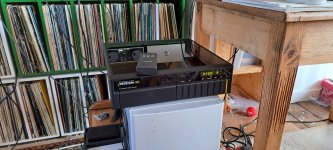
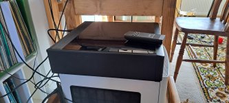
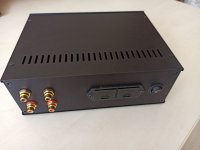
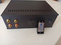
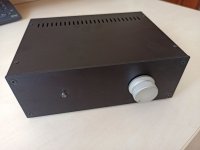
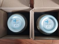
I recently obtained an interesting PowerAmp - Kenwood L-1000 M - manufactured around 1990. Concurrently I was able to locate a service manual as well. I got the Amp since it is a member of Kenwood's famed "L-Series" which was manufactured by Kensonic Labs (also known as Accuphase) for sister company Kenwood.
http://www.thevintageknob.org/KENWOOD/L1000M/L1000M.html
Specs are as follows:
http://www.thevintageknob.org/KENWOOD/L1000M/L1000M-block.html
2x150W @8Ohm - 2x250W @4Ohm
Damping factor : 130
THD 0.006% (20Hz-20KhZ, 130W, 8Ohm)
THD 0.0004% (1kHz, 130W, 8 Ohm)
Frequency response 5Hz-100kHz +0dB -3dB
Signal/Noise Ratio : 115dB (Unbalanced), 125dB (Balanced)
What I'm looking for are ideas how to modify this nice power amplifier to make it even better. It has excellent specs but due to some reason, it didn't receive top grades in German higher end audio journals. (Like Stereoplay, Audio and Hifi-Vision). Maybe because it was too cheap for their preference ? I think the amp originally costed around $3000, that's way below the $10K many good Accuphase poweramps sell for.
It also is full of high quality components. Maybe there might be some "easy tweaks" to unlock the potential of this design, which shouldn't be far too different from Accuphase's own.
http://www.thevintageknob.org/KENWOOD/L1000M/L1000M-edwin.html
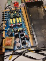
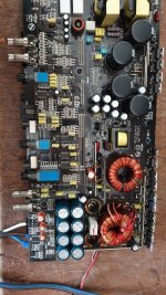
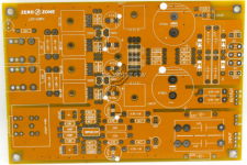
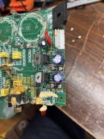
The design has some oddities / goodies
1) Full symmetrical layout
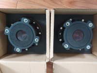
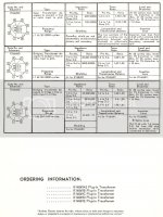
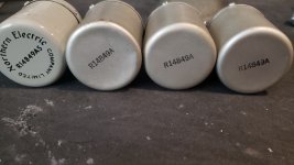
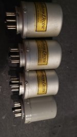
2) 2x 270VA transformers
3) 47000µF caps in the power unit
4) Point to point wiring
Aspects that I found questionable (starting points to modding ?)
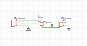
1) Variable resistors (potis) in the input path, one per channel - is this necessary ? does it introduce noise
2) Maybe try to get caps to tighter tolerances - replace elkos with regular caps where possible
3) Get metal film resistors of smallest tolerances (Holco 0.5%) to replace resistors in audio path, at the extreme: use bulk foil types
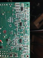
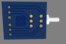
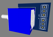
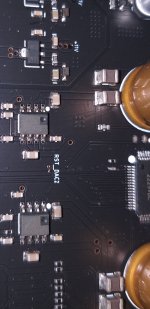
4) The "input" board - uses 2 Opamps : 2x Dual Opamp NJM4580 from JRC / New Japan Radio. While these are ok and relatively low noise, there is still room for improvement in noise and especially slew rate (Contemplating AD797 for example)
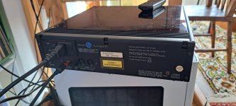
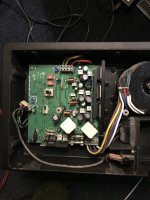
5) There's a switch from XLR to Chinch Input at the back of the Amp. Well, it would make sense to "migrate" the switch to the front and feed it from 2 seperate preamps: one analog and one digital "cross connect" (with highest quality DA/AD) for example..
Just to give the full picture about my endeavour, it wouldn't be me who would do the modding, a german modding shop would carry out the project. However I'd like to be able to provide useful inputs to them, ultimately in the form of a "checklist" and for me as a a "project supervision" tool. Being familiar with most concepts, I know more than basics in electronics, however I've been at odds with the soldering iron whenever I tried it <g>
any comments and ideas welcome. Even more so because I know this is a rather "strange" and "exotic" amp - manufactured by a company with more than a good reputation..
best rgrds from Vienna/Austria
CROSSY