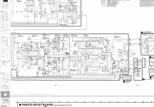
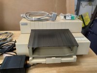
Marantz PM-68 Stereo Amplifier repair and BIASing
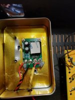
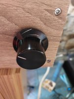
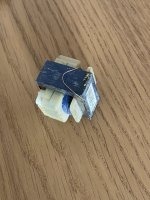
I use lot of time for reading service manual and those forums. Over and over again I opened PDF-file and I tried to think what is wrong and why. It took like 2 years for fix my Marantz PM-68. Only really broken part was main power switch. When I push it I could see led blink once. Then I noticed that I can tune trimmers if I keep power button down. I have changed trimpots better ones. But how to tune those before tunning BIAS. I found Maratz PM-80 youtube video and noticed it looks like my PM-68. PM-80 service manual said I should turn trims to halfway. When I kept power button down PM-68 works just fine also remote control. Then I make sure power button should stay down and not only drive relays. I could see youtube-videos that power-button stays down. So it is latching switch and not momentary switch. There was lots of realys. I ordered power switch but wrong one. I took orginal switch out and I found same switch from ebay. It was ESB82106V 5A/80A250V TV-5 other marks was CSA MM5-4 M 8204 MM5-2 µ + S VDE S LL2 CURS
But why I should buy same switch when there is much better qyality switch.
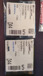
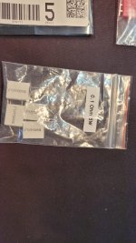
Genuine ALPS SDL1P SDL1P-D ON-OFF PANEL MOUNT POWER SWITCHES 250V 5A/80A JAPAN
Main power switch should take lots of power TV-5 and 80A max.
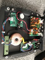
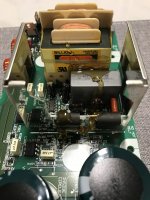
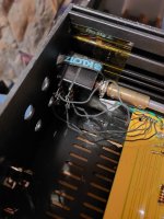
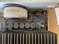
There is large electrical force inside and PM-68 is not small toy to play with. I kept in my mind that one wrong move may kill me. I bought those two big caps 10 000uF. One of them have charged. Even it has travelled one month from China to europe.When I touch it with metal tool it made loud snap and sparks. I did not change those big ones. I am waiting something I don't know what. It will be difficult to take them out.
I broke Fuse holders so I chage those for better ones.
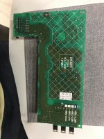
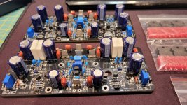
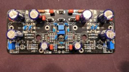
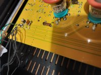
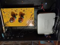
I noticed that circuit boards are really fragile and bendy and conductors broken often. Just because it could not take the heat. I glued metal stick to main power board so that it will not bend so much.
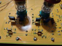
I use lot of solder when I made solderings. Especially I try to make really good work when there will be lots of power and amperes.
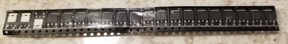
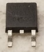
I try to change lots of electrolytic capacitors. But I change some of them back to old ones. I try to choose same size also volume I mean height and width. I buy Nichicon and Nichicon Muse capacitors. I mesured lots of parts and those were fine.
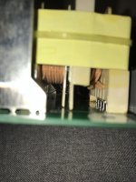
Some of the wires could not take bendings. I have to put some hot glue for both ends where those wires were soldered.
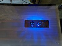
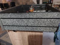
I put two small fans inside. Amlifier have been really hot inside because circuitboards are partly brown.
I have to cut some plastic fasteners because I want to take out circuit-boars much more easily.
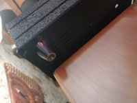
I put one Screw terminal to main power cables so that I could take out the power board much more easy.
I have really thick loudspeaker wires made from copper. At least 12 AWG and 2mm diameter or thicker.
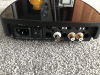
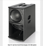
I have subwoofer and it take stereo sound from Tape 2 output and REC selector switch turned to source.
I was really happy when I make sure that new power Switch was almost the same as broken one.
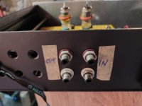
I made small screwdriver from wooden stick, clear plastic film and Heat Shrink Tube.
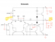
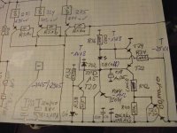
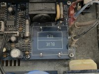
I made BIAS settings over and over again just make sure. PM-68 is Class AB amplifier.
Make sure you connect multimeter wires red to plus and black to minus. Mesure DC millivolts.
Multimeter 200mV means max is 200mV and reading like 12.6 means 12,6 mV
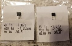
I mesured and tuned BIAS 19mV when amplifier have been turned on over 30 minutes.
DC-offset I tuned about 10mV
My first testing music was Finlandia by composer Jean Sibelius.
https://en.wikipedia.org/wiki/Finlandia
Second test song was Sting Moon over Bourbon Street and those kettledrums at somewhere between 02:39-02:48
Aplifier needs about 20 minutes to warm up and after that it sounds great.
I ordedred lots of parts which I never use.
This is more like hobby to me. Recently I repeared old Tube Radio. It take years to make it work again. I also made adapter between old gramophone connector and modern stereo-audio-input. Transformer was Hammond 560G.
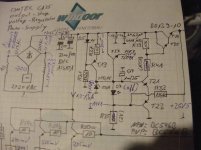
I have made large capacitor discharge tool. Wires and claws and 25W 100K ohm resistor. Old radio needed stronger parts like 400-2000 volts. Modern part can take up to like 60 volts. Circuitboard was metal box and underneath was three-dimensional net of wires.
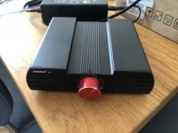
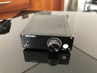
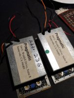
I am also tried to do CMoy headphone amplifiers. First was good. Next three did not work. Tiny errors can make huge impact. Also audio aplifier chips can break really easy. I have also strange groundidng problems. I decided to buy ready-made boards with components soldered. eBay sell high quality and cheap modules. So I have purchased over hundred ready-made circuit boards.


