In fact, I am trying to put it up an an attachment. If that does not work, please message me.
I knew Fried quite well from 1976 on. He was a bit of a sharp operator and a self-promoter, and I later learned he signed engineers to non-disclosure agreements so they would not get the credit they deserved.
It's an interesting document, even if only to show how far today's common practices are light-years opposite from Fried's orthodoxies such as, a woofer should be crossed over at 100Hz, first order, series crossover, and so forth.
That said, the Fried R3 3-way had an amazing midrange timbre, quite reminiscent of the QUAD ESL-57. Sublime on orchestral strings.
Hi
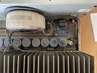
I’m considering a Recap for my Linn Linto phono stage.
Attached is a screenshot of the main PCB.
1. Other than the 14 Capacitors in the attached picture, are there any other Capacitors that need changing ?
2. I read in the various forum, various preferences of Capacitors types that are worthy. Is it that different types are good for different phono stages ?
Which brand/type regardless of budget will give the best performance ?
3. Which internet shop is reliable and sells only original parts ?
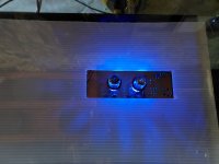
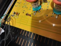
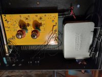
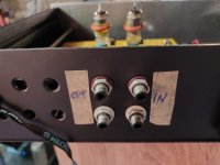
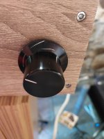
The switches I’ve found so far are only suitable for panels 10mm thick - I presume this means that the threaded barrel is only slightly longer than 10mm. My front panel is 13mm thick. Is anyone aware of an illuminated latch switch that has a long enough threaded barrel for this depth?
Here is some sheets about 6N6P russian double triode noval base tube.
I was working on spice model for my bunch of tube models, have spoted
some notes about the tube that could be of interest for the future experiments with 6N6P tube.
Txt file contains datas fro manode chrs. graph. (GraphClick.app used for extracting values from the graph)
Needing a fast small signal diode for a peak detector, I obtained a couple of NTE109's - packaged individually in carefully labelled plastic bags.
The NTE109 is claimed to be a germanium, fast switching general purpose diode.
I did a simple test (simple half-wave rectifier, loaded with a 2K7 resistor) at 500kHz and to my unpleasant surprise it performed identically to an 1N4148 (testing with a schottky diode for comparison provided a much better recovery time)
I measured the forward voltage drop to around 0.6V with a multimeter - expecting 0.3V from germanium.
This smells standard silicon, but at a (at least) 20 times price tag.
The case (apr. double length of an 1N4148) has no markings, which might indicate something is wrong (even an 1N4148 can have a '4148 printed on the available space).
So my question is now (before contacting the dealer): are NTE109 known victims for fakes?
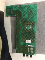
I am working on restoring a nearly destroyed Lafayette KT-550, the less famous step-brother of Hegeman's famous Citation II.
The amp in question was exposed to the elements and needs new PCBs. Because PCB layouts are far outside my area of expertise, and because Hegeman and Ed Duda (the designers of the amp) were no slouches, my initial instinct was to reproduce the originals with only modifications to fit modern parts. But I'm sure, given the decades that have passed and the advent of multi-layered PCBs, there may be a better way.
What do you think? What would you do with the below?
The PCB houses the pre/inverter/driver stages as well as all the feedback loops. Everything highlighted is off-board.
Here is the original single-sided PCB layout:
Here is my two-layer re-creation. Note that I moved C4, C7, C8, C11, and C12 below-board, which is why their silk-screening is not present in this view. Their lead holes are labeled, however.
I'm building a little LM386 based guitar amplifier, and I have some 16v rated capacitors I want to use in a couple locations. I'm running this particular amplifier at 18v (two 9v in series), and using an LM386-4. I'm not great understanding/analyzing at these types of circuits, so I was wondering if anyone could possibly help me determine whether 16v rated caps would be acceptable in the highlighted positions, or if I risk blowing them. I know I can simply get higher rated caps, but at this point I really want to understand this circuit better. Thanks in advance!
Edit: I'm currently using a 4 ohm speaker, but sometimes will plug it into up to 32 ohm speakers.
I'm so not understanding the part value of the caps on this partial schematic, can I get some help in trying to identify them in a more logical system. What does 101p means in essence to 104p, more so, could I get the values in nano or micro farad. the "p" is frustrating me in regards to the usual letters as in "J" or "K" that I'm more used to. I know the p means picofarad but I'm more used to 104 as 100nf. please explain.
I have been playing with the 6SJ7 tube to see if it can handle a 100k load, and it seemed to be able to do it well. I did the bandwidth sweep and did not see any attenuation in the audible range. The B+ was 300V, the plate resistor was 47k, and the screen was set at 75V with Zener diode. I had a 1k potentiometer with a 100 Ohm resistor in series on the cathode as such:
With 75V on the screen, the 47k DC load line went right through the knee of the curve. I noticed the 1k sine wave had the characteristic 2nd order distortion with flattened bottom curve and peaked upper curve when I biased the tube to get a plate voltage of 150V. When I turned the cathode pot down, at 150 Ohm of total resistance, the sine waves evened out and became nice and symmetrical. The plate voltage was around 90V. The input signal was 2V p-p. Output level across the 100k load was about 120V p-p. The upper and lower peaks didn't look flattened, but I can't tell for sure. I have a very rudimentary scope so I can't export the waveform or do FFT. I tried it with a bunch of different tubes and had the same results. It looked like the 6SJ7 likes about 4.5mA. Can someone with proper gears check the circuit and see how much distortion there is? Thanks.
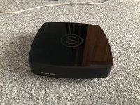
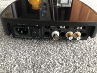
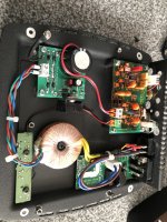
Built to order but never picked up. Subbu V3 with LDO linear PSU built in. It plays 24/192. SPDIF BNC only but I’ll include an RCA connector. Built with solid aluminium caps, FKC filter caps, mains filter and an SPDIF input transformer. Casing is connected to PE, audio GND is lifted so no hum whatsoever. Power on LED is a soft glowing white one. Of course wired for 230…240V mains voltage but it has 2 x 115…120V primary windings.
This item will be sold and the money will go to medical relief in Ukraine (specifically medical relief and not weaponry). The people of Ukraine are suffering this christmas.
Let your heart speak and enjoy a simply very good sounding DAC at the same time. Make me an offer via PM. Shipping only within Europe.
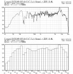
This is poor 4" full range, sold at Japanese shop for 350 yen(2.65 USD) each.
It has a thin press-frame, so it tends to squeak easily, but the sound quality is sufficient for your needs.
Hello
Looking for a pair of magnequest cobalt EXO-45 or 36 outputs for a special project, Will take care of all FedEx express shipping by commercial account.
Please PM me if you something available..
Thank you
Been looking around for refences to testing one can do on a tonearm and drawn a blank, so thought time for a thread on it. I have to admit that I'd never really worried about this until I started getting angst over the (very nicely made) stock arm on my KD-550 second turntable. Japanese S-arms with detachable headshells had a bad press in the 90s, so I had always considered it a step below the straight one piece arms that became vogue. Then I inherited the KD-550 when my father gave up vinyl...
So what can one measure, what should one measure, and what can you do about it? My initial thoughts were
1. Bearing friction/cable snagging over operating arc
2. Resonant modes
3. Damping of said modes.
Of these only the resonant modes seems to be covered with the sort of test suite (test record) that we have as you should be able to see anomalies in a frequency sweep. If this is indeed the case then there is the question of where they are occuring to damp them. In a straight tube this should be easy as will effectively be pipe modes, but in a J or S arm with an SME connector at one end it may be a little harder.
For damping you need some sort of chirp test, which isn't on test records so you need to find another stimulus method. I've never seen a waterfall plot for a tonearm, so I assume this is either considered not important or non-trivial.
I've also been looking at accelerometer options but not found anything small enough to tape onto a tube.
This is the amp I just got in. It's from 2004, I think.
The chassis is well built, but the amp (which has crossfeed) is op-amp based.
Other than improving caps and such, any obvious (easy) improvements possible here?
Say we have two choices in designing, say a center channel. We can use smaller drivers and port them to maybe 50hz to use a 100hz crossover point, or, use slightly larger drivers and use eq, specifically a hi shelf filter to achieve a flat response to 50hz for the same 100hz crossover point.
From my understanding we either want to have a flat response on either side of the crossover to achieve proper summing, or use the natural roll off on a drivers low end if it happens to be right where we want to have the next driver with a lowpass. I presently strive for an octave of response with no beaming through at least an octave also but that’s not pertaining to the thread’s purpose but I’d be happy to hear thoughts on this too.
If we use a helmholtz resonator to achieve flat response an octave below the crossover point there will be group delay differences between the mating drivers through the crossover. If we use slightly larger sealed drivers we should have a more consistent group delay throughout the crossover with the group delay being more in the high shelf filter.
Seems reputable loudspeaker companies will be perfectly fine using bass reflex in all the various components of a home theater system. Is it better, when possible, to use sealed drivers in all but the lowest playing drivers? Maybe even all sealed drivers if power and anything else is more of less equal? I personally will always have dsp in any design I take seriously.
I am looking for a good upgrade of the standard 1N4001 rectifier diodes (to be located in a DAC power supply), I assume a Shottky and fast recovery diode.
The above mentioned link talks about the 1N5819, but there may be other (better ?) alternatives...
What are the best according to your expertise ?
Thank you very much,
Copypasting RIP ENZO thread from Music Electronics Forum:
" RIP Enzo
Yesterday, 12:26 AM
I don't post here much as I usually hang out over on TDPRI, but I did want to let you all know that Enzo passed tonight.
While many people knew him as the all-knowing music electronics technician, he also was an expert in other fields as well, including coin-operated systems (pool tables, washing machines, etc), pinball machines, video monitors and arcade systems, and more things that are too many to list.
If there is any good news, we get the privilege to reference the 36,609 posts he shared with us here, plus more on various other popular forums.
I'll be sharing this link with his wife and family, so please leave any condolences, thoughts, or memories you wish to share.
Remember: Isolate the problem, it's just a guitar amp, and education is what you're left with after you've forgotten what you've learned.
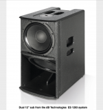
I'm still on the hunt for the "perfect compromise" smallish horn sub. Obviously, some kind of TH will most likely be the answer, but I'm curious about what some companies call a "semi Horn" design. Here's a modern version from DB Technologies, using dual 12" drivers: (below)
I remember years ago that EV made a smallish single 18" like this, and it sounded really punchy. Probably not a lot of LF extension, though. Many other single-drivers subs like this have been offered over the years, though it's not super common. - But what the heck is this DB Tech design? Are both drivers loading the same space? (with some kind of high-tech DSP control?) Is it one small BR sub on top of a massively-compromised TH chamber?
I don't get it, but I'm very curious to know how, and how well, this design works.
I found an old Pioneer VSX-455 dirt cheap, so I bought. I'm now trying to find a remote for it. Does anyone happen to know if a typical universal remote will work on the era of receivers?
Thanks,
Mike
Hi - I have an amp that I made based on the "little gem" amplifier circuit (LM386-based). I want to try to run it through a speaker from an old AM radio, which is a reed-type speaker supposedly with an impedance of 550 ohms (though I might be misunderstanding the schematic). Is there any way to do this while getting a reasonable amount of volume out of the amp/speaker?
My amp is labeled 12AU7-6SN7-ECC82 on two tube sockets,
I would have bet that all 3 tubes had same pin out ...
JJ 6SN7 data sheet shows plate to cathodes are on pins 1,2 and 5,6
Schematic to my amp says plate to cathodes are at 5,6 and 2,3
Pulled up another 6SN7 and holy moly, it shows plate to cathodes 1,3 and 6,8
There is zero consistency. Mark from Blueglow has a 6SN7 diagram matching my setup...
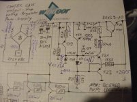
In the attachment the associated schematic diagram (both diagrams nearly identical - the only difference is the polarity).
This voltage regulators feds only the offset servo (TL071), the VAS-stage and the 3V8 regulator for the input stage, but not for the output buffer.
The whole diagram I have posted here (post #25) : Omtec Mono Power Amplifier "CA 25" (CA25) - Schematic wanted
I understand, how works the small 15V regulator part for the offset servo TL071:
T19/20, R37/38, LED D5/D6 and R31/R32 create a current source (appromixately 3-3,5mA) for the zener diode ZD1/ZD2 (15V).
This zener diode is not only connected with the base of T27/T28 which supplies by the emitter ~14V3 to PIN4&7 of TL071.
This zener diode is also connected to the following parts arround the main regulator section consisting of darlington transistor function T25+29/T26+30:
1) base T21/22 and
2) anode LED D7/D8,
This both LED's emits only a very faint red light. I don't think, that is correct. But there are no faulty transistors and resistors.
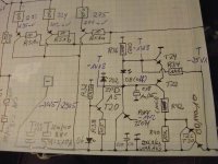
Some questions rises up:
Which task do these parts have together with R35/R36 and R33/R34 ?
and additional I want to know, which voltage regulation range can be realized
and how stable must actually be the voltage at varying loads on the emitter of T29/T30 ?
What could have been the reason to prefer this circuit topology?
Maybe a redesign of this regulator circuit is necessary for a proper resp. better operation.
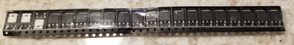
Received this amp with burned power supply. Mosfets and drivers are gone.
Removed all Fets and Gate resistors.
Fet drivers are C2383
and A1013.. Same Pinout as BD139/140 ECB
Two problems:
First:
TL494 and drive card is ok. But one Drivewave has 8V Amplitude, the other 12V Amplitude.... All parts are removed, but it seems, that the problem occurs from mainboard.
Second Problem: Somehow the driver configuration is strange, and doesnt work.
Normally it is E/F follower pair.
But this one got B+ and B- at the base of the transistors.
collectors are collected and goes to the mosfets.
Emitters are collected together and get the drive signal from the TL494.
Has someone infos about that, or ever seen such a configuration?
I have been playing with the idea of making lower tuned tapped family members for my 4-way synergy horn system for quite some time. They will add the bottom octave to the system's repertoire. The TH's that are visible in the picture are tuned to ~32-33Hz and they do not go that low to give the "air vibration" effects near 20Hz, that only very low THD bass systems, that go low enough, can create. The new horn family members will take over where the higher tuned TH's start to roll off.
Given I had already these 4x18" BMS woofers and was at least subconsciously limited to the following size, here's what I came up with. After many hours of trying to squeeze a 10-13Hz horn/TQWT etc. into the same "small" size while keeping good efficiency, I gave up and returned to the original path, ie. maximize the efficiency and settle for adequate extension of ~16Hz that does not have air turbulence and other problems.
Tapped TL seemes to work very well with the BMS woofers and TL's notch after the pass band is good for me since I want to maximize the acoustic low pass. The woofer configuration will be push-pull.
16Hz tapped transmission line (T-TL) vs. 750 litre sealed box with same woofers. Two of these things corner/boundary loaded are ought to make some kind of noise.
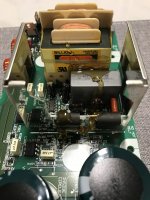
Hi I have a Bose lifestyle pa18-48, which was given to me only problem is that it’s 110v and here in Uk it’s 240v. Is there a way to do this with the existing transformer? There is a wire in between the transformer, I’ll add some photos thank you
Hello one and all, apologies if I am not posting in the best place I took an educated guess. I am pretty new to DIY and in the research phase at this point. I’ve been through all kinds of videos and posts for a number of concepts which I am currently digesting and trying to split up logically then look at how they may work together as a whole. I imagine it will take a bit of time and thought before I make proper sense of things.
So I am ‘theoretically planning’ a build with the understanding I don’t have all the pieces yet and may need to re-imagine things. I think at this time where I am at the electrical stuff is likely my biggest obstacle. Input is very welcome!
As of right now I am imagining a setup in which utilizes 2 subs and 2 monitors above. I want them to be capable of connecting to an audio card like a typical studio monitor would be capable of. I’m also looking to minimize cabling and I’m thinking of having the sub be the audio source in, which will send audio signal from the sub up to the monitor. This means each sub would have 2 amps, 1 for the sub, and 1 which sends out to the monitor above. I know other systems send through however at this time I don’t know electrically what is going on there at all.
I was using the HS8 system as a reference in the basic idea as far as using the sub to send to the individual speakers. My difference however of course is two individual subs leading to the question of stereo. How would I then be able if at all to isolate only a left or right channel on the monitors above. Can I make it modulate ie Left/Right on a switch? I do also believe for sending the audio to the monitor above that once it goes through an amp it would need to be through speaker wire cable or potentially a speak-on? Would it be better to consider saying forget the second amp and cable saving and make the monitors passive in order to simplify some steps between?
Again I am very new to DIY and intend to revisit ideas as I go, I don’t expect to get anything right the first time around and I’ll probably be experimenting for a while before I have a good understanding of things. If I am not making sense with anything please let me know and I can try to elaborate.
I have few latest version Modulus-86 PCBs (https://neurochrome.com/products/modulus-86) for sale. Cost of a PCB is $70 + PayPal fees + Shipping. If interested please send me a PM.
I try to update firmware on the hypex FA502 Plateamplifier. It seems that has withe the second attempt to switch in "boot mode" but it failed. HFD after that always failed to update again. Now the LED p1 blink green and the rest is steady green. After 15 Minutes i tried to reconnect but also failed. I submitted a mail to the support. Is there a chance to bring it back in "normal mode" Second any idea what has been going wrong?
I was reading a comment by BillShurv and he linked to a HFN/RR (HiFi News & Record Review) article. I used to subscribe to the paper magazine a couple of decades ago (or so) and had lost contact with it and wondered what and who had changed. Turns out, not much, there were some very familiar names reviewing hardware and music.
I got to wondering if that was a good thing or not.
Their hearing must have deteriorated, are their ears still golden well into their 70s?
Does it matter?
If they re-reviewed kit from the 1980's now, would they still give the same review?
If they reviewed modern kit with their 1980's ears would they still give the same reviews?
Still, at least the technical analysis is fairly reliable...
Would want to have a minimalist crossover with a single inductor for the jordans and a resistor and single cap for the tweeter if possible. If not a crossover with as few components possible is preferred.
Backstory: Got these minipod speakers for a song but the woofers and tweeters are out of spec (rubber surrounds have dimples and probably need replacing and the tweeters aren’t putting out the same level) having it repaired will cost about the same if I just pull out the drivers and replace them. Jordans became available in ebay and are a direct fit with no modifications with the minipods.
Was sorting my tube collection yesterday and realised I have a whole bunch of EN91 thyratron tubes, I've been thinking of making a tube PSU that can deliver ~200mA at 150-200V and most of the diodes I have are not up to it. The EN91 can handle 500mA which would be great, but I'm not really sure how I'd use a thyratron for a simple rectifier, either full wave or bridge type.
Tried searching around but all I find are references to grid controlled rectifiers where you need to build a little magic box that will tickle the grids just right somehow, but no practical circuit for making this.
Found an old thread here where Hg thyratrons were used for full wave rectification, but they were using the grid instead of the anode and looking at the EN91 datasheet, it seems like it would not like that very much. At least that's my take on it, maybe I'm wrong 🙂
Any got any knowlage on this topic? Maybe I'm not finding any info because it's not a good idea and nobody has done it 😛
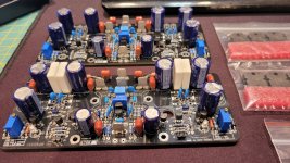
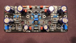
The PeeCeeBee V4 is a great sounding amp. It was designed by a member @shaan and you can find the complete V4 thread here. I built one a few years back and was going to build a 2nd one for my son, but never got around to finishing it, and he lost interest. So.....
I have two, meticulously assembled, V4 Rev 1 amp modules. They are essentially completed except for mounting the 8 output drivers on a suitable heatsink and two other smaller BJT transistors. There are 4, .1 Ohm resistors to mount as well, and one of the boards needs a little LED at location D5. They have never been used, or assembled yet into a working amplifier enclosure. They will need a PSU with +-55VDC.
These modules are in their completed state, including the few loose parts that still need to be installed. The PCB boards I got from shaan directly and are brand new. All of the parts I used where brand new as well and mostly sourced from Mouser in the US.
I'm asking $250 (or reasonable offer) plus postage to your location for both modules and the parts shown in the pictures. Postage amount will be determined to your country if you are not in the US. If in the US, I will ship Priority Mail Small Box. What you see is what is included in this offer. PM if interested.
Hi New guy here. I have a kenwood kac 5020 and kac7020 with all original wiring. Does anyone know if I can just plug in 8 pin din to rca jacks and hook to newer boss stereo unit. Just trying to help out with my sons Jeep
thanks for any help
chris
I'm building a enclosure for my Tang Band W8-740P. Does anyone have any experience with double bass reflex enclosures. This is for studio use and it will be a downward firing bass. I have unlimited space for it. I would like it to be able to handle between 20 to 100Hz. 30 to 80Hz also works.
Hello. I want to create an amp with Wifi and Dsp that can provide two channels of 50 Watt at 4ohm & and one channel of 300 watts at 4 ohm.
After doing a lot of research, I was thinking combining this two modules:
1.-Arylic Up2stream amp 2x50Watts with Dsp and wifi.
2.- IcePower 300AS1 connected to the Mono XOUT of the Arylic.
So I can benefit of doing the croosovers and some Eq in the Arylic ACPworkbench, and adding 300Watt channel for a subwoofer.
I want to put this Amplifier into a the speaker enclosure I want to start to work on.
I am just starting with this amazing hobby of building speakers and I would like to know your thoughts. ? Will it work properly? Am I going in the right direction? Is there a better way to achieve my goal?
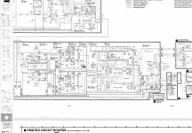
Found this site while searching on issues with a SVI 3205.
I have a SU-V670 on the table, which goes into protection mode after running for a few minutes.
I measured the output of the SVI 3205 on pin 3, and found approx -40VDC… it changes more negative as the unit heats up.
I removed the SVI 3205 to make sure it didn’t cause problems, but I still have DC on the output
I have removed and checked Q452, Q460 and Q464, as I have close to negative supply on the collector of Q452 and base of Q460/464.
IC401 is also running very hot. I have -58VDC on Q402, which I can’t figure out how it’s possible - any ideas?
I have attached a part of the schematics…
As a side note - I do have a degree in electronics, but I haven’t worked with it for more than 25 years… I’m a bit rusty.
I just bought a lot of Fostex drivers. Perhaps an idiotic move. I would like to buy diaphragms, parts/ whole drivers for the following units. I know this is a difficult if not impossible search:
I liked so much the standard Starving that decided to build one with boutique components. Probably a crazy step but I assure you it sounds decently and clearly better.
Chassis is heavy aluminium, painted and wood film finish on front panel. Feet are conical and can accomodate screws or counterfeet. Volume pot is tad best version, knob is a heavy and thick one. Components SMPS Filter is housed in a caption covered aluminium box, No switch on/off, direct plug to amps. Eichmann orca's, Duelund wire where matter, 2x Sfernice as resistor. The circuit is updside down to facilitate setting change, 2x char croft and 2x Vishay VAR, 2x arch, Lid cover not realized, will include a plastic raw, as you see in pictures.
What to ask...if you look at the crude costs it will never be sold. Let me try to ask 400 our but will accept any fair offer that come first. Don't feel bad to drop my request price. I need to move on, as I actually use a top doc with preamp included.
Will ship in Europe for sure, other countries ask. PayPal is fine of course.
It plays extremely musical. I preferred it to B1 Nukorg and ACA pre, but of course this is a subjective opinion. in stock form when I built the basic one it was inferior to the quoted preamps. So components here seemed to work.
Thanxs
My entire system, except for my modern AVR is vacuum tube. Most of it is kit based, modern and vintage.
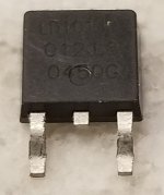
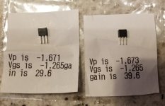
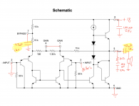
I really wanted a solid state amplifier for when I wanted a lot of power. I came across a Hafler DH-200 on eBay. Appears to be kit built and largely untouched since being build.
I replaced the bad power switch, broken fuse holder, all the capacitors on the driver boards and inspected the rest of the solder joints, finding a few bad ones.
Set the Bias at 275 mA. The 200 does NOT have a DC offset adjustment.
Well, I measured the DC offset on the left channel I have -66 mV and on the right channel I have -331 mV
I have been told that to correct this I need to replace the Q1, Q2, Q5, and Q6 transistors and they need to be gain matched. I can purchase new transistors from NTE but I cannot seem to find a matched pair.
Manual shows these as
Q1/Q2: 2N5550
Q5/Q6: 2N5401
I am well aware that there is more than one person selling replacement boards for these units. Redesigned, and “upgraded” but I like to listen to things as they were designed. I would really like to fix the DC offset on this Amplifier using the original configuration.
Does anybody have any insight as to where I can find matched pairs of these transistors? Or if my diagnosis is incorrect, what should I be looking at?
Hello everybody .
Do you know if there is an archive somewhere in which to find the graph of the frequency response of everyone in woofer on the market?
I own Yamaha DBR12 diffuser, I would like to find the woofer graph but I don't find anything.
I only found this link: https://djmania.es/p/altavoz-woofer-12-yf998c00-yamaha-db-12
Some might be interested in this. The MetOpera is also re-recording early wire recordings. And as always, when in West Orange NJ, please visit the Edison National Historic site.
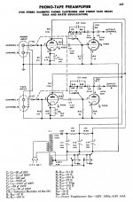
I found the below schematic from a Chinese language tube manual published in 1972 that was translated from one of the US tube manuals. I just can't figure out which tube manual. My guess is that it's most likely from RCA as 7025 was a popular tube in those famous RCA schematics, including the passive RIAA one. This one is feedback from the output tube plate to the grid, almost like a predecessor of EAR 834p. Anyone knows about this circuit? Its B+ voltage is rather low, around 150VDC. I think adding a cathode follower or FET source follower will make it more versatile.
Hey, I have a question for you regarding an amp of sorts. And I am fairly handy but am not what I would call knowledgeable about electronics.
I just got a Yamaha Clavinova CVP-7 (for free!). It was made in 1986. The keyboard (76-key) is great, the cabinet is great, and the built-in 30wx2 amp and speakers are great. I love the idea of just siting down and turning it on as opposed to setting up a keyboard on a stand, plugging in the pedal, hooking up to an external amp, bla bla bla.....
BUT...the one weakness of the 1986-era piano is the 1986-era sounds. The piano is, well, 1986. It won't fool ya, unlike these awesome new ($$$$$$) Clavinovas.
So, my solution is to buy a Kurzweil MIDI module and use the sounds from that, which I know will be great. The thing is fully MIDI-able and the implementation charts match up for the pedals, etc... The Kurzweil is a little 1/2 rack with feet and even a front power switch so it will just sit unobtrusively right on the piano lid.
Here's the thing: The Yamaha has no line in, and I want very badly to output the Kurzweil module back to the piano's built-in amp. I want a self contained unit, you know?
So....can I add line ins to my Clavinova? Would it be as simple as tapping into the master volume, running from the hots to the hot pins of a set of RCA or 1/4 inch jacks, commons to ground, and installing the RCA jacks somewhere in the panel of the Clavinova? Maybe using a DPDT switch inline to switch back and forth between the internal sounds and the Kurzweil module's outputs (this is all stereo, by the way). There are RCA line out jacks on the Clavinova's panel and I would be willing to cannibalize those as I can not for the life of me see myself using the built-in tones for recording, ever.
If you have any thoughts let me know. Thanks!
I was able to address this. The power amp section is a completely separate board and I was able to remove the piano lid and trace the cable that runs from pre to power amp. I'll simply jumper in there and add a set of jacks and I'm all set.
Or maybe not. I realized this would not address the issue of using the external module's sounds through the headphones, which I really want to be able to do. So I need to go in somewhere pre-headphoen jack. I guess I'll give the lid another lift and have a look once more.
Hello!, have some questions for the Hypex UcD700HG with HxR linear power supply, especially the Vdr circuit I've added to the stock S700 power supply.
TLDR It is ok for the UcD700 Vdr circuit and regulator of choice shown in the schematic below?, or should I add another small transformer solely to power the Vdr circuit? as I've seen on some builds, I asking because the xformer tabs used will be shared with some relays and two 24V fans and I'm worried that may introduce noise etc, although the fans will only be activated by independent heatsink thermal sensors set to close at 45~50deg so they will be off most of the time.
After recent Samson S700 amp failure denoted on this thread I've finally opted to modify it with Class D amp modules rather than fully restoring it with equivalent transistors, or even designing/ordering new PCB's with newer amp topology, time consuming and need lots of parts plus protection circuitry etc.
So I'm leaning toward 2x Hypex UcD700HG with HxR since they use split(+/-) voltage unlike the ICEpower 500A, and because it seems to have good reviews around the web, plus the Samson S700 stock power supply specs seems to be ok for them, it will be used as midbass amplifier.
The S700 Transformer Spec are as follow: HV:
Pri: 120VAC BRN/GRY Sec: 58VAC CT RED/YEL/RED
LV:
Sec: 22VAC GRN/GRN Sec: 22VAC CT YEL/BLU/YEL
The VA is unknown but the transformer weighted almost ~15.5LBS so I guesstimate is around ~750VA or so.
Also the 22V tabs I will be using for the Vdr is the one who powers the step-start plus two 24v fans so I guess should have more than ~500mA, the other 22V tabs are center tapped but will be already used for the front panel metering and the +/-VSIG.
Here is the slightly modified/simplified stock S700 power supply with some added bits for the UcD700:
Regards
EDIT: Found some errors in the schematic due the cut/copy/paste edition, I will design a simpler schematic in EasyEDA and order some premade PCB's for simplicity, then update this thread after testing them.
Hello: how do I connect a bluetooth transmitter to the output RCA-type speaker output jacks of my home audio receiver? Notice the plural -- jacks. I see a lot of bluetooth transmitters with 1 set of rca jacks, that is 1 white for common, 1 red for hot. So do I need to buy 2 transmitters if I have 2 (rca-type) speaker out jacks on the a/v for 1 "set" for stereo? The a/v also has a toslink connection. Will that connect to a bluetooth transmitter (with toslink) for both (stereo) speakers? I will be getting bluetooth speakers to be totally wireless.Thank you.
I ran two dedicated circuits for my audio and video system, twisted 3 wire, over size wire inside conduit that is not connected on the outlet end, 2 ft apart full length of the run, plastic boxes, hospital grade outlets.
Now I need to test for AC line noise to see what filtering I might need. For now and at least a couple of years will use regular local power supply, eventually will have enough solar, batteries, good inverter, etc...
Also have a lot of smart meters 20 ft away so spending considerable time and funds on shielding as we plan to be here for some time in our RV.
All that said, looking into a way to test the line noise on the AC so I can best determine the proper filtering needed, DIY only, not going to buy some hugely over marketed and priced line conditioner, just not something I would do unless no other choice but I doubt really needed.
I know how to use an O-scope, retired Navy tech, and other gear but I only want to spend the minimal amount to get the job done.
I also need a good meter to check the smart meters, etc, so much BS when searching anything online these days it makes it hard to know what to believe so I am asking here because some of you know.
(I did search, might not of used the right terms, did not find what I was looking for.)
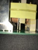
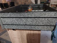
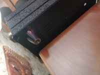
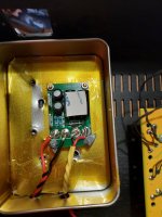
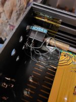
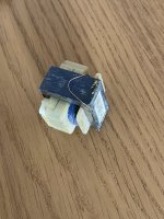
Hello, due to bad transportation I have just found out a little transformer detached from a pcb in my just acquired HK 1.5 signature.
I think the problem is easy to solve but I don’t know how to reconnect it.
Where should I solder the two tiny copper wires?
Should I glue it to avoid that it detaches again?
Here are some pictures.
Thank you so much for helping
I feel a bit miserable, the package was not well made, inspite of many recommendations :-(
I try to find a ground on the 2-bit rotary switch to switch the Otto board.
I have configured the Otto according to the integration guide with VCC to S with a 4k7 resistor.
Any suggestions how I could get this to work?
Hello.
I had a pair of brand new or WTB: 1 piece Accuton C173-6-191E ceramic midrange and trying to cjhjeck fitting to one unit I broke the cone.
In this point I'm very pissed off and I dont know what to do so:
I wnat to buy, or to sell, whatever it comes first or 1 piece of Accuton C173-6-191E ceramic midrange.
Please, send me youir offer to sell or buy.
Attached you will find pictures from my broken unit. the other unit is safe in it box unopened.
I have a FocusRite rack mount mixer for sale. Successfully connects to my Windows 10 based DAW system via its Dell Firewire card, using the FocusRite software available at FocusRite website. Plays audio from that system.
The only reason I mention it here is because in addition to 8 Inputs, it also has 8 Outputs, which I assume are individually assignable audio channels. Good specs too, it's FocusRite; if you ever wanted to experiment with multichannel audio.
Great deal if your PC / Mac can cope with the Firewire connection.
I thought I'd share a project I've been working on for the past few months.
Login to view embedded media
It started when I decided to make some upgrades to my Technics SL-20. I updated the RCA wires to terminals and a new ground connection. Upgraded the cartridge and rewired the tonearm with silver wires. The improvements were eye-opening. But soon after, It began to have some speed issues.
That's when I decided to look into buying a new turntable. I liked the Rega and Fluance offering, but if I was going to upgrade, I really wanted something with a separate motor, and arm board that would allow easy upgrades to the tonearm in the future. Anything I found with features like that was far beyond my price range, so I decided to try to build my own.
Here are the parts I used:
Plinth: MDF (three layers) with walnut veneer
Arm board: Curley maple (solid)
Sub platter: Tango spinner with bearing sleeve
Platter: Rega acrylic
Micro Seiki MA-202L tonearm, which I rewired with Cardas 4X33 Tonearm Wire Cryo Treated from Take Five Audio.
Nagaoka MP-110 cartridge with Nagaoka headshell.
Adjustable feet from Amazon
I initially wanted to use a Maxon motor, but I stumbled upon a Portescap 28L28-416E.49 motor for $55 on eBay. It was new-old-stock, so it's Swiss-made, rather than the newer ones made in India.
The spindle for the motor is just a brass motor shaft coupling that I machined a groove into for the belt I made from polyester thread.
The most difficult part by far was the motor control. I lost count of how many different threads I've read on this subject. Lots of good ideas out there. In the end, I decided to go with an open-loop system using an Arduino Uno and Adafruit Motor Controller. It's not perfect, but It will do until I learn more, and build a closed-loop system.
I'm posting all my plans, photos, schematics, and Arduino sketch. Hopefully, this post will help someone who wants to take on a project like this.
The green board in the image represents a DC/DC converter used to convert the 12v incoming to 5v to power the Arduino. The 12v feeds off the incoming terminals and goes to the power input of the Adafruit Motor Shield.
Marantz 2270 power board, replaced the caps and the small transistors, checked h805 and it looks ok.
The trouble is that I can't adjust the output to 35 volts. The trimmer r809 has been checked and it looks ok.
Turning the trimmer doesn't change the voltage between j803 and j802 as the manual says it should though it does change the voltage to
the base of h806.
I'm hoping to DIY something like the iFi's AC iPurifier or the Russ Andrews' AC Silencer...................
I understand that these are to be plugged on to a vacant wall socket in the house that will help "clean" up the noises thrown into the mains by the common household appliances.
Many years back I written down some notes from one of the websites (not sure if it was TNT or Acoustica or somewhere else) but I just can't it anymore. If I remember correctly it would involve a few X/Y rated capacitors and maybe a discharge resistor.
No, I'm not looking at a main conditional like the one from Jon Risch, have already built one.
I am looking for a decent chip (decent sounding, low THD, good internal protection, good availability, etc) able to do about 10W Po, a bit more into 4R, a bit less into 8R.
I am fully aware LM1875 running from just +/- 15V can do that nicely. Nevertheless, for some reason I am looking for an alternative designed for the 10W Po,max class.
Login to view embedded media
Click, the right click (open in new tab) to see it full size to be able to read it.
It's theoretical for the most part, currently. But I've wasted far too many bytes explaining it and failing. A picture says....
Clocks are a concern, with so many "off the shelf" modules either forcing they be clock source, or in the cases of BT modules and the PCM5102, just not caring about master clock at all. I can do clock routing, I can do frame stuff/drop.
I'm not aiming for HiFi SOTA in the first pass. Those STM32F411 mux front ends are pretty maxed out routing 2 I2S and 2 SPI. At first I may just limit the internal buses to 48K,16bit. Most of the hardware is capable up to 192K,32 and the Atmel USB bridges go WAY, WAY higher.
Should be noted. It is possible, though impractical that all inputs can be routed to all outputs at the same time. In the real world however its more likely that one bus will be music with heavy EQ going to the headphone output and the other bus being everything else at low gain/low eq and appearing everywhere. Even to the point that a notification on my phone will come out the speakers and headphone or whatever I choose independent of other sources.
Seas 25TV-EW 10" Woofer.
From a Dynaco A-25 speaker
8 ohm, DC resistance 6.4 ohms
2674 date code
No voice coil rubbing, cone and surround are in good condition.
When I consulted with a few independent speaker designers back in the late 80s to early 90s, we used modified ignition timing lights to check the performance of various cone geometries and materials in LF drivers to find their limitations when operating out of their designated bandwidth at higher drive levels. I got the idea from designing and testing light weight valvetrains used in high rpm race engine applications ie. Spintron testing. You'd be shocked how bad the cone of an LF cone driver deforms at higher output levels and various frequencies.
I remember KEF and B&W doing laser interferometry research many decades ago. I'm surprised this area of technology hasn't filtered down into the diy crowd yet with all the access we now have to information pertaining to speaker building.
Dad recently took a turn for the worse. And his Parkinson's has entered its final stage. He suffers from Sundown syndrome and Psychosis.
So I have been researching up on how to help.
Things we are trying.
1. Calming music, / Nature sounds
2. Guided meditation and breathing exercises.
Then I came across this short clip which says it will help. Its a regular song. But the signal bounces from one ear to the next. To me it just gave me a headache after some time. But they say it helps so I plan to try it.
I also need to look into playing special frequencies.
There are a lot of really old smart guys on this forum. Any help or ideas to help would be much appreciated.
My gut tells me Audio can help. Im just not sure how will share any info I find.
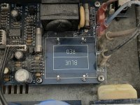
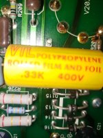
I have a VTL ST 85 amp that I want to upgrade the coupling caps in. The current caps are VTL branded show .33k 400V. All of the possible caps from the likes of Mundorf, Solen, Infinicap etc. seem to be labeled in microfarads or uf. If the common nomenclature for the K after the .33 is picofarads, then what is the microfarad or uf. conversion? Is it a .33uf cap? .00000033uf? Thanks in advance.
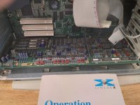
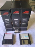
So once upon a time I used MLSSA for measurement, LEAP for enclosure simulation. I don't think I can run any of that any more, certainly not on my Macs. I'm wondering what softwares folks are using now
For rough "put in some Thiele-Smalls and generate boxes like they are electrical circuits"
For designing with actual response and complex impedance data like LEAP did
Something that would let you simulate different voice coils and windings. Like SpeaD but not $1700, I just want to do some curiosity modeling. Jeez I wonder whatever happened to the Excel sheet I used to use to calculate voice coils...
Big bonus points if someone can point me to a package that can do tone burst simulations.
My journey in things music- and sound-related started with singing, then playing instruments to accompany/support the singing, then much later into the tech aspects of music and sound. I have never lost sight of the fact that, while there's a large overlap in skills required to do them well, there's a huge experiential difference in playing or creating an instrument versus being one.
In the most general sense, a musician is someone who makes music. What qualifies as 'music' is a whole 'nuther matter. But it's interesting to note that singers rarely refer to themselves as musicians, unless they also play. But players almost always do.
And that's pretty much where I land. Singers are singers, and players are players. And they may or may not be musicians, except when referred to in the abstract, when they are. But the participants in the community definitely sense and make a distinction.


